Tag: consumables

  • CK20 TIG Torch Support: Parts Lookup and Buying Checks

    CK20 TIG Torch Support: Parts Lookup and Buying Checks

    CK20 TIG Torch Support

    CK20 TIG torch support starts with identification, then moves to parts verification. If the torch body, back cap, collet body, cup, or gas lens do not match the CK20 pattern, the wrong consumable set can create fit-up problems, gas coverage issues, or early wear. This guide is for buyers, welders, and maintenance teams who need a practical way to check what fits before ordering.

    Key Takeaways

    • Confirm the torch model and series before ordering any consumables.
    • Check the torch breakdown against the support page, not memory or shop habit.
    • Verify cup, collet, gas lens, and back cap style as a matched set where needed.
    • Use Unknown (Verify) for any fitment detail that is not confirmed by the source page or your own machine records.
    • Inspect wear parts for heat damage, thread wear, and loose fit before reuse.

    What the WSP CK20 support page is for

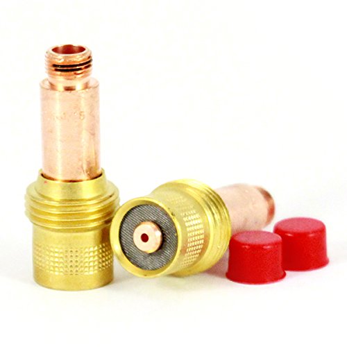
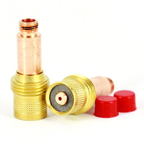
    The Weld Support Parts CK20 TIG Torch Support page is the starting point for machine and consumable lookup. The page is intended to help you find CK20 compatible machines, CK Series 2 consumables, gas lenses, cups, collets, and breakdown support. Use it as a reference point when you need to confirm what the torch uses or when you are matching replacement parts after a service call.

    Open the lookup page here: CK20 TIG Torch Support.

    Before you buy anything, compare the torch numberplate, handle markings, lead style, and consumable stack. If the torch is not clearly identified, treat compatibility as Unknown (Verify).

    Check, inspect, verify: buying process

    1. Check the torch ID. Read the torch body, handle, and lead connection. If the marking is worn off, confirm from machine records or the service ticket.
    2. Inspect the current consumables. Remove the cup, collet, and back cap. Look for thread damage, cracked ceramic, burned O-rings, and discoloration from overheating.
    3. Verify the stack order. Gas lens, collet body, collet, and cup must match the torch setup. If any part is missing or substituted, record it before reordering.
    4. Match by function, not appearance. Two parts can look similar and still differ in thread form, length, or internal bore. If the source page does not confirm it, mark it Unknown (Verify).
    5. Cross-check replacement quantity. Buy enough for the active torch and a small service reserve. Do not assume all CK parts in stock are interchangeable without verification.

    Troubleshooting support checks

    If the torch is running poorly, use a basic check sequence before replacing parts.

    Gas coverage problems

    • Check: Is the cup cracked, blocked, or loose?
    • Inspect: Look for soot, spatter, or heat damage on the gas lens and collet body.
    • Verify: Confirm the cup size and gas lens style against the CK20 support reference. If not confirmed, Unknown (Verify).

    Arc instability or wandering arc

    • Check: Is the tungsten properly centered and secured?
    • Inspect: Look for worn collet jaws, damaged collet body threads, or a bent tungsten stickout path.
    • Verify: Confirm the torch is assembled with the correct CK Series 2 consumables if that is what the lookup page identifies for your setup.

    Overheating at the front end

    • Check: Is the duty cycle being exceeded for the application?
    • Inspect: Look for darkened cups, soft back cap seals, and burned components near the nozzle end.
    • Verify: Confirm the torch is actually the CK20 variant and not a similar torch with different duty limits or consumable geometry. Unknown (Verify) if not documented.

    Parts and breakdown support workflow

    Use the support page when a torch is already apart or when a replacement order is needed after failure. Start with the torch breakdown, then identify the wear parts in this order:

    • Back cap
    • Collet
    • Collet body or gas lens body
    • Cup or nozzle
    • Insulators or seals, if used in that assembly

    If a part is damaged beyond a visual ID, remove one confirmed sample from the line and match it directly. Do not order by description alone if the stack has been modified in the field. If a helper note, machine log, or purchase record does not confirm the part number, treat the replacement as Unknown (Verify).

    What to inspect on used CK20 consumables

    • Threads: Check for galling, cross-threading, and incomplete engagement.
    • Ceramic cups: Inspect for chips, cracks, and heat checking.
    • Collets: Look for jaw spread, oxidation, and poor tungsten grip.
    • Gas lens screens: Check for clogging, distortion, or impact damage.
    • Back caps: Verify seal condition and straightness.

    If any item fails inspection, replace it as a set when needed. Mixing worn and new components can make the problem harder to diagnose.

    Safety notes

    • Shut down power and gas before disassembly.
    • Allow the torch to cool before handling cups, collets, and gas lenses.
    • Do not reuse parts with cracked ceramic, stripped threads, or heat-damaged seals.
    • Use the correct PPE for hot work and sharp ceramic fragments.
    • If machine compatibility is not confirmed, do not force-fit consumables. Mark it Unknown (Verify) and recheck the torch ID.

    FAQ

    How do I know if my torch is CK20 compatible?

    Start with the torch marking, machine records, and the consumable stack already installed. Then compare it to the CK20 TIG Torch Support page. If the ID is unclear, treat compatibility as Unknown (Verify).

    Can I mix CK consumables from different setups?

    Not without verification. Some consumables may appear similar but differ in length, thread form, or internal geometry. Verify the exact stack before mixing parts.

    What should I replace first if the torch has poor gas coverage?

    Inspect the cup, gas lens, and collet body first. Check for cracks, clogging, and poor fit. Replace the damaged part and confirm the assembly order.

    Where should I start when I need breakdown support?

    Use the CK20 support page, then break the torch down into its consumable stack and compare each piece against a confirmed sample or documented machine record.

    Sources Checked

    Any compatibility or fitment detail not directly confirmed from the source page or your shop records should be treated as Unknown (Verify).

    Disclosure: As an Amazon Associate, Weld Support Parts may earn from qualifying purchases.

  • Plasma Consumable Compatibility Chart

    Miller Electric 256033, XT60 Plasma Torch Consumable Kit
    “>Miller Electric 256033, XT60 Plasma Torch Consumable Kit

    Plasma consumable compatibility is determined by torch model, torch series, and the exact stack order of the parts in the torch head. Do not match parts by appearance alone. A tip, shield, swirl ring, or retaining cup that looks close can still be the wrong part.

    Key Takeaways

    • Verify the torch model before ordering any plasma consumable.
    • Compatibility depends on the full stack: electrode, tip/nozzle, shield, swirl ring, retaining cup/cap, and any O-ring or deflector used by that torch.
    • Do not mix parts across torch families unless the manufacturer lists them as compatible.
    • Incorrect stack order can cause poor arc start, unstable cutting, rapid wear, or torch damage.
    • Unknown (Verify) for any part fitment not confirmed by the torch manufacturer or a verified parts listing.

    Compatibility Chart

    Consumable / Part What to Verify Common Fitment Risk
    Electrode Torch family, amperage range, and matching tip set Wrong electrode can cause poor arc start or short life
    Tip / Nozzle Orifice size, amperage rating, and torch series Incorrect tip can affect cut quality and heat concentration
    Shield / Drag Shield Whether the torch uses a drag shield, standoff shield, or no shield Wrong shield can change stand-off distance and cut angle
    Swirl Ring Exact torch model and internal gas-flow design Wrong swirl ring can disrupt gas rotation and arc stability
    Retaining Cup / Retaining Cap Thread type, body shape, and torch series Improper retention can prevent correct assembly
    Deflector Whether the torch uses a deflector in the consumable stack Missing or wrong deflector can alter gas flow and shield position
    O-Ring Size and location called out by the torch manual or parts list Wrong seal can create leak or assembly issues
    Gouge Tip / Gouge Shield Whether the torch supports gouging accessories Gouging parts are not universal; verify before use

    How to Confirm Plasma Consumable Compatibility

    1. Read the torch nameplate, machine manual, or torch handle marking.
    2. Identify the exact torch model and series.
    3. Match each part number in the manufacturer parts list.
    4. Check whether the torch uses standard cutting consumables, drag consumables, or gouging consumables.
    5. Verify the stack order shown in the service manual before assembly.
    6. Replace worn parts as a complete set when the torch design requires it.

    Troubleshooting Support

    Problem: Consumables wear out too fast

    Check amperage setting, cutting technique, air quality, and whether the consumables match the torch model. Mixed or incorrect parts can shorten life.

    Problem: Arc starts but cuts are unstable

    Inspect the electrode, tip/nozzle, swirl ring, and shield for correct fit and damage. A wrong stack order can cause unstable gas flow.

    Problem: Parts will not assemble

    Confirm the torch family and part numbers. Do not force parts together. Threading and body geometry are not universal.

    Problem: Excessive spatter or bevel

    Verify tip size, cut speed, standoff, and whether the shield type matches the intended cutting method.

    Product / Parts Reference

    Miller Electric 256033, XT60 Plasma Torch Consumable Kit

    Short description: Plasma Torch Consumable Kit, For Use With XT60 Torch, 20 to 60 Amps, Application Plasma Cutting, Includes (3) Electrodes, (3) Tips, Drag Shield, Deflector, O-Ring, Swirl Ring, Retaining Cup, Gouge Tip, Gouge Shield, Silicone Grease, Weatherproof Storage Box.

    Compatibility note: This kit is listed for use with XT60 torch. Do not assume compatibility with other torch models. Verify against the machine and torch manual before purchase or installation.

    Miller Electric 256033, XT60 Plasma Torch Consumable Kit

    Miller Electric 256033, XT60 Plasma Torch Consumable Kit

    Plasma Torch Consumable Kit,For Use With XT60 Torch,20 to 60 Amps,Application Plasma Cutting,Includes (3) Electrodes, (3) Tips, Drag Shield, Deflector, O-Ring, Swirl Ring, Retaining Cup, Gouge Tip, Gouge Shield, Silicone Grease, Weatherproof Storage Box

    View at Arc Weld Store

    Safety Notes

    • Power off and isolate the plasma cutter before replacing consumables.
    • Allow the torch and consumables to cool before handling.
    • Use clean, dry air as required by the torch system.
    • Do not run mismatched consumables in an attempt to finish a job.
    • Follow the manufacturer manual for stack order and torque/fit guidance.

    FAQ

    Can I use plasma consumables from a different torch series?

    Only if the manufacturer lists them as compatible. Otherwise, assume no. Unknown (Verify) until confirmed by the parts catalog or service manual.

    Are all electrodes and tips interchangeable?

    No. Electrode and tip compatibility depends on torch family, amperage range, and internal consumable design.

    What causes a torch to burn through consumables quickly?

    Common causes include incorrect parts, dirty air, excessive amperage, poor standoff, and incorrect assembly order.

    Is the retaining cup the same as the retaining cap?

    Not always. Naming varies by manufacturer. Verify the exact part name used in the torch parts list.

    Sources Checked

    • Miller Electric 256033 XT60 Plasma Torch Consumable Kit product listing provided in the request
    • General plasma torch consumable compatibility principles
    • Unknown (Verify) for any torch-specific cross-compatibility not listed by the manufacturer
  • PAPR Filter Replacement Checklist

    ESAB Savage A40 PAPR Main Filter Replacement - NIOSH Certified, Pack of 1
    “>ESAB Savage A40 PAPR Main Filter Replacement - NIOSH Certified, Pack of 1

    Use this checklist to decide when a PAPR filter replacement is due and to reduce the chance of restricted airflow during welding. Treat filter condition as a maintenance item, not a guess. If the blower, hose, or face seal is also suspect, check those parts before installing a new filter.

    Key Takeaways

    • Replace the filter when airflow drops, alarms occur, or the filter is visibly loaded.
    • Do not assume a filter is still usable based on time alone. Check condition and system performance.
    • Inspect the blower, hose, battery, and helmet seal at the same time.
    • If the system performance remains poor after replacement, the cause is likely elsewhere.

    Filter Replacement Checklist

    • Check airflow: Confirm the blower moves air normally at startup. If airflow is weak, investigate loading or system faults.
    • Check alarm status: Any low-flow alarm or abnormal warning is a replacement trigger until the cause is verified.
    • Inspect the filter surface: Look for heavy dust loading, discoloration, damage, or collapse.
    • Check the housing and seal: Confirm the filter seats correctly and the housing closes as designed.
    • Review exposure conditions: Heavy particulate loading will shorten filter life. Unknown (Verify) for exact service interval.
    • Verify the prefilter, if used: A blocked prefilter can make the main filter appear failed early.
    • Confirm hose condition: Cracks, loose connections, or kinks can mimic filter problems.
    • Check battery status: Low battery voltage can reduce blower performance and trigger false filter concerns.

    When to Replace the PAPR Filter

    Replace the filter when any of the following are true:

    • Airflow is reduced and does not recover after cleaning or inspection of related parts.
    • The unit alarms for low flow or restricted operation.
    • The filter is visibly loaded with dust or welding-related particulates.
    • The filter is damaged, deformed, or not seated correctly.
    • Contamination or exposure history makes reuse uncertain.

    If the unit still alarms after replacement, use the troubleshooting steps in the airflow guide and check the blower, hose, battery, and seals.

    Support and Troubleshooting

    For airflow-related problems that look like filter failure, use this guide first:

    PAPR Welding Helmet Airflow Troubleshooting: Low-Flow Alarm, Filter Loading, Hose Leaks, Battery, and Blower Checks

    That article covers common causes of reduced airflow that can lead to unnecessary filter replacement.

    Product / Parts

    If you need the supported replacement part for this topic, use the ArcWeld listing below.

    ESAB Savage A40 PAPR Main Filter Replacement - NIOSH Certified, Pack of 1

    ESAB Savage A40 PAPR Main Filter Replacement – NIOSH Certified, Pack of 1

    Upgrade your safety gear with the ESAB 0700002403, Savage A40 PAPR Main Filter. This essential component is designed for those who prioritize both health and performance in their workplace. The PAPR main filter replacement is specifically engineered to ensure the highest level of air quality while you work, allowing you to focus on the job at hand without constant concerns about airborne contaminants. With rigorou…

    View at Arc Weld Store

    Product note: ESAB Savage A40 PAPR Main Filter Replacement – NIOSH Certified, Pack of 1. Compatibility beyond the listed product name is Unknown (Verify). Use only where the equipment model matches the replacement part specification.

    Safety Notes

    • Do not continue welding with a PAPR that alarms for low flow until the cause is corrected.
    • Do not reuse a damaged or overloaded filter.
    • Verify the replacement part against the helmet/blower model before installation.
    • Follow the equipment manual and site respiratory protection procedure. If there is any mismatch, remove the unit from service until verified.

    FAQ

    How often should a PAPR filter be replaced?
    Unknown (Verify). Replacement interval depends on dust loading, duty cycle, and the equipment manual.

    Can I clean a loaded PAPR filter and reuse it?
    Usually no. If airflow is restricted or the filter is damaged, replace it. Do not improvise cleaning methods unless the manufacturer allows it.

    What if the new filter does not fix the low-flow alarm?
    Check the blower, hose, battery, seals, and installation. The issue may not be the filter.

    Do I need to replace the prefilter too?
    If the system uses one, inspect it at the same time. A blocked prefilter can reduce airflow and shorten main filter life.

    Sources Checked

    • Allowed internal link: PAPR Welding Helmet Airflow Troubleshooting: Low-Flow Alarm, Filter Loading, Hose Leaks, Battery, and Blower Checks
    • Allowed ArcWeld product listing: ESAB Savage A40 PAPR Main Filter Replacement – NIOSH Certified, Pack of 1

    Category: PAPR Helmet Support

    Related Weld Support Guides

  • When to Replace Oxy-Fuel Torch Tips

    Bernard Style Contact Tips - American Torch Tip 1593 Long 3/32" for Quality Welding
    “>Bernard Style Contact Tips - American Torch Tip 1593 Long 3/32" for Quality Welding

    Oxy-fuel torch tips wear over time. A tip that is dirty, distorted, or damaged can cause poor flame shape, unstable cutting, and inconsistent heating. Knowing when to clean and when to replace the tip helps keep the torch operating safely and predictably.

    Key Takeaways

    When to Clean a Torch Tip

    Start with cleaning when the tip is only showing light contamination. Common signs include carbon buildup around the face, minor spatter, or restricted flow from dirt in the passages. Use the correct tip cleaners and do not force tools through the orifices. Oversizing the opening will ruin the tip.

    When to Replace a Torch Tip

    Replace the tip when cleaning does not restore normal performance. Typical replacement signs include:

    If the tip has been overheated or dropped, inspect it carefully. Visible damage is a strong reason to replace it.

    Troubleshooting Support

    If performance changes suddenly, check more than the tip. Problems can also come from gas pressure settings, loose connections, damaged torch seals, dirty gas passages, or incorrect tip size for the job. If the torch still runs poorly after cleaning and checking setup, replace the tip and inspect the rest of the torch assembly.

    Replacement Parts

    For welding support and replacement consumables, use the correct part for the torch and application.

    Product fitment for oxy-fuel use: Unknown (Verify). This part may not be an oxy-fuel torch tip. Confirm torch type, thread, size, and intended process before ordering or installing.

    Safety Notes

    FAQ

    How often should I replace an oxy-fuel torch tip?

    There is no fixed interval. Replace it when wear, damage, or performance problems cannot be corrected by cleaning.

    Can I keep using a tip that still lights?

    Not if the flame is unstable, the cut quality is poor, or the tip is visibly damaged. Lighting alone does not mean the tip is serviceable.

    What is the first step before replacing a tip?

    Inspect and clean it if the issue looks like contamination rather than physical wear. If the tip is damaged or the orifice is no longer correct, replace it.

    Sources Checked

    Related Arc Weld Part

    Bernard Style Contact Tips - American Torch Tip 1593 Long 3/32" for Quality Welding

    Bernard Style Contact Tips – American Torch Tip 1593 Long 3/32" for Quality Welding

    Introducing the ATTC 1593, a top-quality Bernard style contact tip designed for enhanced performance in your welding tasks. This long contact tip features a diameter of 3/32" and is crafted specifically for use with American Torch Tip welding equipment, making it a reliable choice for welders looking to optimize their material handling and results. Made from high-quality materials, the ATTC 1593 contact tip offers…

    View at Arc Weld Store
  • Plasma Cut Has Beveled Edge

    Hypertherm 220674 Plasma Cutting Shield - T45v Hand Cutting Shield, 1 Pack
    “>Hypertherm 220674 Plasma Cutting Shield - T45v Hand Cutting Shield, 1 Pack

    A beveled edge on a plasma cut usually means the arc is not centered through the kerf. The most common causes are torch angle, travel speed, worn consumables, incorrect standoff, and poor air quality. Start with the cut setup, then inspect parts, then check the air system.

    Key Takeaways

    Diagnose the Cut

    1) Check torch angle

    Hold the torch square to the plate. Even a small tilt can create a bevel on one side of the cut. If the torch is hand-held, watch for side lean during the full cut path, especially on long cuts and corners.

    2) Check travel speed

    Travel speed affects kerf shape. If you move too fast, the arc trails and the cut leans. If you move too slow, the arc can wash out the lower edge and increase dross. Make one change at a time and test on scrap.

    3) Inspect consumables

    Worn or damaged consumables can make the arc unstable. Check the electrode, nozzle, and shield for erosion, pitting, heat damage, or clogging. If the shield is damaged or worn, replace it before continuing. The Hypertherm 220674 Plasma Cutting Shield is one available part for compatible T45v hand cutting setups; exact compatibility beyond the listed product title is Unknown (Verify).

    4) Verify standoff and contact

    If standoff is too high, the arc can spread and lose cut squareness. If the torch is dragging when it should not, the shield or tip condition may be affecting arc control. Follow the machine or torch manual for the correct stand-off method.

    5) Check air quality

    Moisture, oil, and debris in the air line can cause rough cuts and edge angle changes. Drain the compressor tank, inspect filters, and confirm the air supply is clean and dry. Air pressure and flow requirements are torch-specific and Unknown (Verify) without the machine manual.

    Troubleshooting Support Sections

    If the bevel is consistent on one side

    If the bevel changes during the cut

    If edge quality is poor with fresh consumables

    Product / Parts

    Hypertherm 220674 Plasma Cutting Shield – T45v Hand Cutting Shield, 1 Pack

    This shield may be used when the existing shield is worn or damaged. Use only if it matches the torch setup and manual requirements. Compatibility details beyond the product title are Unknown (Verify).

    Hypertherm 220674 Plasma Cutting Shield - T45v Hand Cutting Shield, 1 Pack

    Hypertherm 220674 Plasma Cutting Shield – T45v Hand Cutting Shield, 1 Pack

    Introducing the Hypertherm 220674 Hand Cutting Shield, your essential companion for plasma cutting tasks. This high-quality plasma cutting shield is designed to protect both your workspace and yourself. Made by Hypertherm, a trusted name in plasma cutting technology, this product ensures superior performance and durability. The Hypertherm Hand Cutting Shield is perfect for both professionals and DIY enthusiasts. I…

    View at Arc Weld Store

    Safety Notes

    FAQ

    Why does plasma cut beveled edge happen?

    It usually happens when the arc is not centered through the cut path. Torch angle, travel speed, consumable wear, and air quality are the main checks.

    Can bad air cause a bevel?

    Yes. Wet or contaminated air can make the arc unstable and change edge angle.

    Should I replace the shield first?

    If the shield is worn, damaged, or heat-affected, replace it. If the shield looks normal, check nozzle, electrode, torch angle, and air supply before replacing more parts.

    What setting should I change first?

    Start with torch angle and travel speed, then inspect consumables. Exact cut settings are torch and material dependent and Unknown (Verify) without the manual.

    Sources Checked

  • Plasma Cutter Not Piercing Cleanly

    Hypertherm 220674 Plasma Cutting Shield - T45v Hand Cutting Shield, 1 Pack
    “>Hypertherm 220674 Plasma Cutting Shield - T45v Hand Cutting Shield, 1 Pack

    If a plasma cutter is not piercing cleanly, the usual cause is a setup problem rather than a major machine fault. Start with air quality, consumable condition, ground connection, torch angle, and pierce technique. Small errors in any of these areas can leave a ragged start, excessive dross, or a failed pierce.

    Key Takeaways

    Troubleshooting Steps

    1. Check air pressure and air quality

    Plasma cutting depends on clean, dry, correctly regulated air. Low pressure can produce a weak, unstable arc. Water, oil, or heavy contamination can cause sputtering and poor pierce quality.

    2. Inspect consumables

    Worn or damaged consumables are a common reason a plasma cutter is not piercing cleanly. The electrode and nozzle must be in good condition for a focused arc.

    3. Verify ground clamp placement

    Poor work return can make the arc start erratically and cause a messy pierce. The clamp must make solid metal-to-metal contact on clean material.

    4. Check pierce height and torch angle

    If the torch is too close, molten metal can blow back into the shield and nozzle. If it is too high, the arc can spread and fail to pierce cleanly.

    5. Reduce pierce demand on thicker or coated material

    Thick plate, rusty plate, painted plate, and galvanized material can make piercing harder. Start with a clean spot if possible. If the plate is thick, give the arc enough time to fully transfer before moving.

    6. Check torch and machine condition

    If air, consumables, and grounding are correct but the pierce still fails, inspect the torch body, leads, and machine output for damage. Intermittent cable faults, heat damage, or loose connectors can reduce performance.

    Product / Parts Support

    When consumables or shielding parts are worn, replace them with the correct torch parts. For hand cutting shield support, see:

    Hypertherm 220674 Plasma Cutting Shield - T45v Hand Cutting Shield, 1 Pack

    Hypertherm 220674 Plasma Cutting Shield – T45v Hand Cutting Shield, 1 Pack

    Introducing the Hypertherm 220674 Hand Cutting Shield, your essential companion for plasma cutting tasks. This high-quality plasma cutting shield is designed to protect both your workspace and yourself. Made by Hypertherm, a trusted name in plasma cutting technology, this product ensures superior performance and durability. The Hypertherm Hand Cutting Shield is perfect for both professionals and DIY enthusiasts. I…

    View at Arc Weld Store

    Hypertherm 220674 Plasma Cutting Shield – T45v Hand Cutting Shield, 1 Pack

    Use only if it matches the torch model and application. Compatibility for your machine is Unknown (Verify) unless confirmed by the torch manual or parts list.

    Safety Notes

    FAQ

    Why does my plasma cutter start but not pierce cleanly?

    Most often it is low air pressure, contaminated air, worn consumables, or poor ground contact.

    Can a bad shield cause poor piercing?

    Yes. A damaged or incorrect shield can affect arc focus and increase spatter. Verify the correct shield for the torch model.

    Should I drag the torch during the pierce?

    Only if the torch and process are designed for drag operation. Otherwise, maintain the correct standoff distance and start upright. Unknown (Verify).

    What is the fastest test for a bad pierce issue?

    Check air pressure, replace visibly worn consumables, and clean the ground point. Those three checks solve many start-up problems.

    Sources Checked

    Related Weld Support Guides

  • Exothermic Cutting Rod Will Not Stay Lit

    Arcair 94-463-032, Slice 3/8" Conversion Kit
    “>Arcair 94-463-032, Slice 3/8" Conversion Kit

    If an exothermic cutting rod will not stay lit, start with oxygen delivery, rod condition, and starting technique. Most ignition problems come from inconsistent gas flow, a worn consumable, or a poor start angle.

    Key Takeaways

    Troubleshooting Support

    When an exothermic cutting rod not staying lit becomes repeatable, work through the setup in order. Do not change multiple variables at once.

    1) Check oxygen supply technique

    Use a steady oxygen supply. Low flow, blocked passages, or rapid trigger changes can extinguish the cut as soon as the rod tries to establish the burn. Confirm the oxygen valve, hose, and torch path are open and operating normally.

    2) Inspect the rod condition

    Rod condition matters. A rod that is damp, bent, damaged, or contaminated may not stay lit. Store consumables dry and handle them cleanly. If the rod coating or end condition looks abnormal, discard it and try a new rod.

    3) Verify the starting technique

    The rod needs a clean, deliberate start. Hold the correct position, strike consistently, and keep the oxygen engaged as required by the process. If the rod is lifted too soon or the start is inconsistent, the burn can drop out.

    4) Check for setup mismatch

    Make sure the torch, consumable, and conversion hardware match the process being used. If the system has been modified, compatibility is Unknown (Verify) until confirmed by the equipment documentation.

    5) Look for wear in the torch path

    Restricted flow, damaged seals, or worn internal components can interrupt oxygen delivery. Inspect the torch and related parts for damage, dirt, or blockage.

    Support Section: Parts and Conversion Hardware

    If you are troubleshooting a persistent ignition problem and the setup uses compatible Arcair hardware, the related support article may help compare symptoms and causes.

    For conversion-related setup checks, one available part is:

    Product link:

    Arcair 94-463-032, Slice 3/8" Conversion Kit

    Arcair 94-463-032, Slice 3/8" Conversion Kit

    Introducing the Arcair 94-463-032, Slice 3/8" Conversion Kit, an essential addition to your cutting tool arsenal. This conversion kit is designed to enhance the performance of your existing cutting equipment, ensuring precision and efficiency in your cutting tasks. The Arcair 94-463-032 is specifically engineered to fit seamlessly with compatible models, providing a reliable solution for your cutting needs. Whethe…

    View at Arc Weld Store

    Safety Notes

    FAQ

    Why does the rod light and then go out?

    Common causes are weak oxygen flow, poor starting technique, or a rod that is damp or damaged.

    Can I keep using a rod that will not stay lit after several tries?

    No. If ignition remains unstable, replace the rod and inspect the torch setup. Repeated failed starts can indicate contamination or a supply problem.

    Should I adjust oxygen flow first or replace the rod first?

    Check oxygen delivery first, then test with a fresh rod. That sequence helps isolate the fault faster.

    Is the Arcair conversion kit a guaranteed fix?

    No. The conversion kit is a hardware option, not a diagnosis. Use it only if the system compatibility is confirmed. Otherwise, compatibility is Unknown (Verify).

    Sources Checked

    Related Weld Support Guides

  • TIG Torch Gets Too Hot During Welding

    TIG Torch Gets Too Hot During Welding

    If you are dealing with tig torch overheating, treat it as a setup or duty-cycle problem first. Excess heat at the torch can damage the body, burn consumables, and reduce shielding gas performance. The cause is usually current demand, poor cooling, loose connections, restricted gas flow, or a torch body that is not suited to the job.

    Key Takeaways

    • High heat at the torch usually points to too much amperage for the torch setup, poor technique, or worn parts.
    • Check torch body condition, cable routing, connections, gas flow, and consumables before replacing major parts.
    • Overheating can shorten tungsten life, damage collets and cups, and increase the chance of arc instability.
    • Use replacement parts that match the torch family and amperage requirement. Compatibility details not listed here are Unknown (Verify).

    Troubleshooting: Why the Torch Is Getting Too Hot

    1. Amperage is too high for the torch body

    Running more current than the torch can handle will build heat quickly. This is the first item to check when the handle, head, or cable becomes uncomfortable to touch during normal welding intervals. If the torch is near its limit, reduce amperage or move to a torch body designed for the job. Exact duty-cycle limits for your setup are Unknown (Verify).

    2. Torch body is worn or damaged

    Internal wear, loose fittings, or heat damage can make the torch run hotter than normal. Inspect the body for cracking, loose head alignment, damaged insulators, and signs of prior overheating. If the torch body has been degraded, repair or replacement is the correct fix, not higher gas flow or a larger cup alone.

    3. Poor electrical contact is creating resistance heat

    Loose collet bodies, worn consumables, dirty threads, and poor connections in the power path can add resistance and create local heat. Clean and tighten all serviceable joints. Replace parts that no longer hold properly.

    4. Shielding gas coverage is not stable

    Restricted gas flow, leaks, or a damaged cup can force longer arc time and higher heat input at the torch. Check the gas line, fittings, regulator, and nozzle area for leaks or blockage. If the gas stream is unstable, the arc can become harder to control and increase torch load.

    5. Cable routing is adding heat and strain

    A tight bend, twisted lead, or cable dragged across hot work can raise torch temperature and reduce performance. Route the torch lead with a smooth bend radius and keep it away from direct contact with hot metal. If the cable insulation is damaged, remove the torch from service.

    6. Duty cycle is being exceeded

    Even a torch that is correctly sized can overheat if it is used beyond its intended duty cycle. Shorten arc time, add cool-down breaks, or shift to a torch setup that is better matched to the amperage and joint size. Published duty-cycle data for the exact setup is Unknown (Verify).

    Support Checks That Help Isolate the Problem

    • Inspect the tungsten, collet, collet body, cup, and back cap for discoloration or heat damage.
    • Check whether the torch overheats faster on long beads than on tack work.
    • Compare heat buildup at low and high amperage to see whether the issue tracks current demand.
    • Confirm gas flow is consistent at the torch and not restricted by kinks or damaged fittings.
    • Verify that the torch body matches the welding process and current range. Exact compatibility is Unknown (Verify) unless documented by the manufacturer.

    Parts and Replacement Considerations

    If the torch body itself is the weak point, replacing it can solve recurring heat problems better than swapping consumables repeatedly. For a rigid air-cooled option, one available part is the Weldtec WT-26 Rigid Torch Body, 200A Air Cooled, 70 Degree Head for Reliable Welding.

    This part is provided through the allowed ArcWeld product link:

    Weldtec WT-26 Rigid Torch Body, 200A Air Cooled, 70 Degree Head for Reliable Welding

    Weldtec WT-26 Rigid Torch Body, 200A Air Cooled, 70 Degree Head for Reliable Welding

    Introducing the Weldtec WT-26 Torch Body, a top-tier choice for professionals in need of a reliable and durable welding solution. Designed for use with gas and capable of handling up to 200 amps, this rigid torch body ensures exceptional performance in a variety of applications. The WT-26 features a standard 70-degree head, which allows for increased maneuverability and accessibility in tight spaces. With its air-…

    View at Arc Weld Store

    Use this only if it matches your torch family and welding setup. Exact compatibility with your machine, leads, and gas setup is Unknown (Verify).

    How to Reduce Torch Heat During Welding

    • Lower amperage if the weld procedure allows it.
    • Shorten arc time and allow cooling breaks.
    • Keep the torch lead straight enough to avoid sharp bends and pinch points.
    • Replace worn consumables before they create resistance or unstable arc behavior.
    • Check all gas and power connections before continuing production work.
    • Use a torch body that is sized for the application instead of pushing a smaller torch past its limit.

    Safety Notes

    • Stop welding if the torch body, cable, or connector becomes excessively hot to touch.
    • Do not handle damaged insulation, cracked housings, or burnt consumables without proper cooldown.
    • Hot torches can cause burns even after the arc is off.
    • Use proper PPE and follow the machine and torch manufacturer instructions.
    • If overheating is repeated, remove the torch from service until the cause is corrected.

    FAQ

    Why does my TIG torch get hot so fast?

    Common causes are high amperage, poor duty-cycle management, worn parts, loose connections, restricted gas flow, or a torch body that is not suited to the application.

    Can a bad tungsten make the torch overheat?

    Yes, indirectly. A poor tungsten setup can make the arc unstable and increase heat load on the torch and consumables.

    Should I replace the torch or just the consumables?

    If the torch body is cracked, loose, or repeatedly overheating under normal use, replacement may be the better option. If the issue is worn consumables or loose fittings, start there first.

    Is the WT-26 right for every TIG setup?

    Unknown (Verify). Match the torch body to your amperage, process, lead configuration, and machine requirements before ordering.

    Sources Checked

    • Allowed ArcWeld product:
      Weldtec WT-26 Rigid Torch Body, 200A Air Cooled, 70 Degree Head for Reliable Welding

      Weldtec WT-26 Rigid Torch Body, 200A Air Cooled, 70 Degree Head for Reliable Welding

      Introducing the Weldtec WT-26 Torch Body, a top-tier choice for professionals in need of a reliable and durable welding solution. Designed for use with gas and capable of handling up to 200 amps, this rigid torch body ensures exceptional performance in a variety of applications. The WT-26 features a standard 70-degree head, which allows for increased maneuverability and accessibility in tight spaces. With its air-…

      View at Arc Weld Store
    • Allowed internal link: Aluminum ER 5554 3/64″ X 5lb. MIG Welding Wire Spool By Washington Alloy – Weld Support Parts Blog

    Related Weld Support Guides

  • Plasma Cutter Not Cutting Through: Causes and Fixes

    A plasma cutter that fails to cut through material typically indicates issues with air supply, consumables, or machine setup. This problem reduces cut quality, increases dross, and can damage the torch if ignored. Diagnosing the root cause quickly restores performance and prevents unnecessary wear.

    Key Takeaways

    • Insufficient air pressure is a leading cause of poor cutting performance
    • Worn consumables reduce arc energy and cut penetration
    • Incorrect amperage settings limit cutting capability
    • Slow or inconsistent travel speed affects cut-through
    • Moisture in air supply degrades plasma arc quality

    Problem / Context

    Plasma cutting relies on a high-temperature ionized gas stream to melt and eject metal. When any part of the system—air supply, power, or consumables—is compromised, the arc loses effectiveness. This results in incomplete cuts, excessive slag, or arc instability.

    Root Causes

    • Low air pressure: insufficient airflow reduces arc force
    • Moisture contamination: water in air disrupts plasma stability
    • Worn consumables: degraded electrodes and nozzles reduce performance
    • Incorrect amperage: not matched to material thickness
    • Slow travel speed: excessive heat buildup without full penetration
    • Poor ground connection: unstable arc behavior

    Solution / Explanation

    • Verify air pressure meets machine specifications
    • Install air dryers or filters to remove moisture
    • Replace consumables regularly based on wear
    • Adjust amperage according to material thickness
    • Maintain consistent travel speed during cutting
    • Ensure clean and secure ground clamp connection

    Specs / Verification Notes

    • Air Pressure: Unknown (Verify per machine manual)
    • Amperage Range: Machine dependent
    • Consumable Life: Usage dependent
    • Cut Thickness Capacity: Unknown (Verify)
    • Air Quality Requirement: Dry, oil-free air

    Comparison Table

    CauseSymptomImpactFix
    Low Air PressureWeak arcNo full cut-throughIncrease pressure
    Worn ConsumablesWide arcPoor cut qualityReplace parts
    Moisture in AirArc sputteringInconsistent cutsDry air supply
    Low AmperageSlow cuttingIncomplete penetrationIncrease output

    Safety Notes

    Follow ANSI Z49.1 safety standards for plasma cutting. Ensure proper grounding and use appropriate PPE including eye protection and gloves. Never operate a plasma cutter with damaged consumables or unstable air supply.

    FAQ

    Why is my plasma cutter not cutting all the way through?

    This is usually caused by low air pressure, worn consumables, or incorrect amperage settings.

    Can bad air quality affect plasma cutting?

    Yes. Moisture or oil in the air supply disrupts the plasma arc and reduces cutting efficiency.

    How often should consumables be replaced?

    Replacement depends on usage and material, but worn consumables should be changed as soon as cut quality declines.

    Next Step

    Check air supply quality and consumable condition before the next cut. Adjust settings based on material thickness and confirm stable operation on scrap material.

    Sources Checked

    • ANSI Z49.1 Safety in Welding and Cutting
    • Plasma cutter manufacturer’s operation manuals
    • AWS cutting process references (general guidance)
  • Plasma Cutter Won’t Pierce Metal: Causes and Fixes

    A plasma cutter that fails to pierce metal will produce arc instability, excessive spatter, or no full penetration. This issue is typically related to air supply, consumable wear, or incorrect setup parameters. Identifying the restriction point in the system is critical for restoring proper cut initiation.

    Key Takeaways

    • Insufficient air pressure is a leading cause of failed pierce
    • Worn consumables disrupt arc focus and energy transfer
    • Incorrect amperage or travel setup prevents full penetration
    • Material thickness must match machine capability

    Problem / Context

    Plasma cutting relies on a high-velocity ionized gas stream to melt and eject metal. When the system cannot pierce, the arc may start but fail to transfer enough energy into the material. This results in surface gouging instead of a full cut-through.

    Root Causes

    • Low air pressure or flow: weak arc and poor metal ejection
    • Moisture in air supply: destabilizes plasma arc
    • Worn electrode or nozzle: reduces arc concentration
    • Incorrect amperage setting: insufficient heat input
    • Excessive stand-off distance: arc loses intensity before contact
    • Material too thick: exceeds machine rating

    Solution / Explanation

    • Verify air compressor output meets cutter requirements (pressure and CFM)
    • Install a moisture separator or dryer to remove water contamination
    • Inspect and replace consumables if wear is visible
    • Set amperage appropriate to material thickness
    • Maintain correct torch height during pierce and cut
    • Confirm material thickness is within rated capacity

    Specs / Verification Notes

    • Air Pressure Requirement: Unknown (Verify)
    • Air Flow (CFM): Unknown (Verify)
    • Amperage Range: Machine dependent
    • Maximum Pierce Thickness: Unknown (Verify)
    • Consumable Type: Model-specific

    Comparison Table

    IssueSymptomCorrection
    Low Air PressureWeak arc, no penetrationIncrease PSI/CFM
    Worn ConsumablesWide arc, spatterReplace electrode/nozzle
    Moisture in AirArc instabilityAdd dryer/filter
    Incorrect SettingsIncomplete pierceAdjust amperage

    Safety Notes

    Follow ANSI Z49.1 for safe cutting practices. Ensure proper ventilation and use appropriate eye and face protection rated for plasma cutting. Disconnect power before servicing consumables or air systems.

    FAQ

    Why won’t my plasma cutter pierce thick steel?

    The material may exceed the machine’s rated pierce capacity or settings may be too low.

    Does air pressure affect piercing?

    Yes. Low pressure reduces arc force and prevents molten metal from being expelled.

    How often should consumables be replaced?

    Replace when wear is visible or cut quality declines. Frequency depends on usage and material.

    Next Step

    Check air supply and inspect consumables before the next cut. Correct setup and maintenance resolve most piercing failures without equipment changes.

    Sources Checked

    • ANSI Z49.1 Safety in Welding and Cutting
    • Plasma cutter manufacturer manuals (general reference)
    • Air compressor and filtration guidelines
  • Listen with Audible