Tag: consumables

  • Hypertherm 220976, Shield, Pack of (1): Replacement Part Breakdown

    Hypertherm 220976, Shield, Pack of (1) is a replacement consumable support part for plasma cutting setups. For buyers and maintenance teams, the key question is not only whether the part is available, but whether the shield you are replacing matches the torch, consumable stack, and cutting conditions in service. That verification matters because shield mismatch can drive poor cut quality, excess dross, shortened consumable life, and downtime.

    This article breaks down how to inspect the existing shield, verify the replacement path, and support purchasing decisions without guessing at compatibility. Product-specific technical details not supplied in the source material should be treated as Unknown (Verify).

    Key Takeaways

    • Hypertherm 220976 is a replacement shield part sold as a pack of one.
    • Verify torch model, consumable family, and existing part number before ordering.
    • Do not assume compatibility from appearance alone.
    • Inspect for arc damage, heat distortion, thread wear, and contact-face erosion before replacing.
    • If any technical detail is not confirmed in the source data, treat it as Unknown (Verify).

    What this part is used for

    A shield is part of the front-end plasma consumable system. In general service use, it helps protect the nozzle area and supports stable cutting by managing arc exposure and physical wear. Exact torch-family compatibility for Hypertherm 220976 is Unknown (Verify) unless confirmed by the machine manual, torch parts list, or manufacturer lookup.

    How to inspect the worn shield

    Before replacement, examine the removed part under good light. Use these check steps:

    • Check the edge profile: Look for rounded edges, notching, melting, or irregular erosion.
    • Inspect the bore and face: Search for spatter buildup, cracking, and heat checking.
    • Verify thread condition: If the shield threads onto the torch or retaining system, confirm they are not crossed, stripped, or galled.
    • Inspect for discoloration: Severe blueing, blackening, or warped metal can point to overheating or incorrect torch setup.
    • Check fit history: If the part has been loose, difficult to install, or repeatedly damaged, verify the rest of the consumable stack and torch components.

    Troubleshooting before you replace the shield

    Shield damage is often a symptom, not the root cause. Use this support sequence:

    1. Check air quality: Verify the plasma gas supply is clean, dry, and within the system’s required range. Exact requirements are Unknown (Verify).
    2. Inspect the consumable stack: Confirm nozzle, electrode, shield, and retaining components are all from the correct family for the torch. Do not mix unknown parts.
    3. Verify installation torque or seating: If the part is loose or seated incorrectly, arc instability and accelerated wear can follow. Torque values are Unknown (Verify).
    4. Check torch height and cutting technique: Excessive standoff, torch collision, or poor pierce technique can damage the shield quickly.
    5. Inspect for machine faults: If wear is recurring, review arc start behavior, gas flow issues, and any fault codes from the system controller.

    Replacement decision checklist

    Use this short verify list before purchasing Hypertherm 220976 or any equivalent-looking part:

    • Verify the current part number from the installed shield or the machine manual.
    • Check the torch model and consumable series.
    • Confirm whether your system uses a shield, retaining cap, or other front-end geometry.
    • Match the old part by part number, not just by appearance.
    • Confirm the replacement is a genuine or approved part for your maintenance standard. If not confirmed, treat it as Unknown (Verify).

    Product and parts section

    The identified product for this draft is Hypertherm 220976, Shield, Pack of (1), ASIN B012Y64ZUS. For purchasing convenience, use the provided product module:

    No products found.

    Do not use the product listing as a substitute for technical verification. The listing confirms the item reference, but compatibility with your torch remains a separate check.

    Support notes for buyers and maintenance teams

    If the shield is part of a planned maintenance kit, align the replacement cycle with shop usage rather than waiting for complete failure. In high-duty plasma work, shields often reach the point where cut quality begins to fall before the part is visibly broken. That is why inspection intervals matter.

    If the shield fails early, review the full consumable stack and operating practices. A new shield will not correct poor air supply, collision damage, incorrect consumable installation, or a mismatched torch setup.

    Safety notes

    • Shut down and isolate the plasma system before servicing consumables.
    • Allow hot parts to cool before handling.
    • Wear gloves and eye protection when inspecting removed consumables.
    • Do not touch live torch components.
    • Follow the machine manufacturer’s lockout and service procedures.

    FAQ

    Q1: Is Hypertherm 220976 a shield or a full consumable kit?
    A: Based on the provided source data, it is a shield sold as a pack of one. Other kit contents are not confirmed and should be treated as Unknown (Verify).

    Q2: Can I match this part by appearance alone?
    A: No. Plasma consumables can look similar across torch families. Verify the part number, torch model, and consumable stack before ordering.

    Q3: What causes shields to fail early?
    A: Common causes include poor air quality, incorrect installation, torch collisions, excessive pierce stress, and mismatched consumables. Exact failure thresholds are Unknown (Verify).

    Q4: Should I replace the shield by itself or with the whole front-end set?
    A: Replace based on the wear pattern and the maintenance standard for your shop. If multiple parts show wear, inspect the full stack and verify the correct replacement family before deciding.

    Sources Checked

    • Provided Amazon registry product reference for Hypertherm 220976, Shield, Pack of (1), ASIN B012Y64ZUS
    • Task instructions and allowed product data supplied in the request

    For final purchase or service approval, verify against the machine manual, torch parts list, or manufacturer support documentation before installation.

    Disclosure: As an Amazon Associate, Weld Support Parts may earn from qualifying purchases.
  • Lincoln Electric KP2744-040T Copper Plus Contact Tip 350A .040 in (1.0 mm) Tapered, 10 pack: Product Breakdown

    Lincoln Electric KP2744-040T Copper Plus Contact Tip 350A .040 in (1.0 mm) Tapered, 10 pack: Product Breakdown

    Product not found.
    “>Lincoln Electric KP2744-040T Copper Plus Contact Tip 350A .040 in (1.0 mm) Tapered, 10 pack

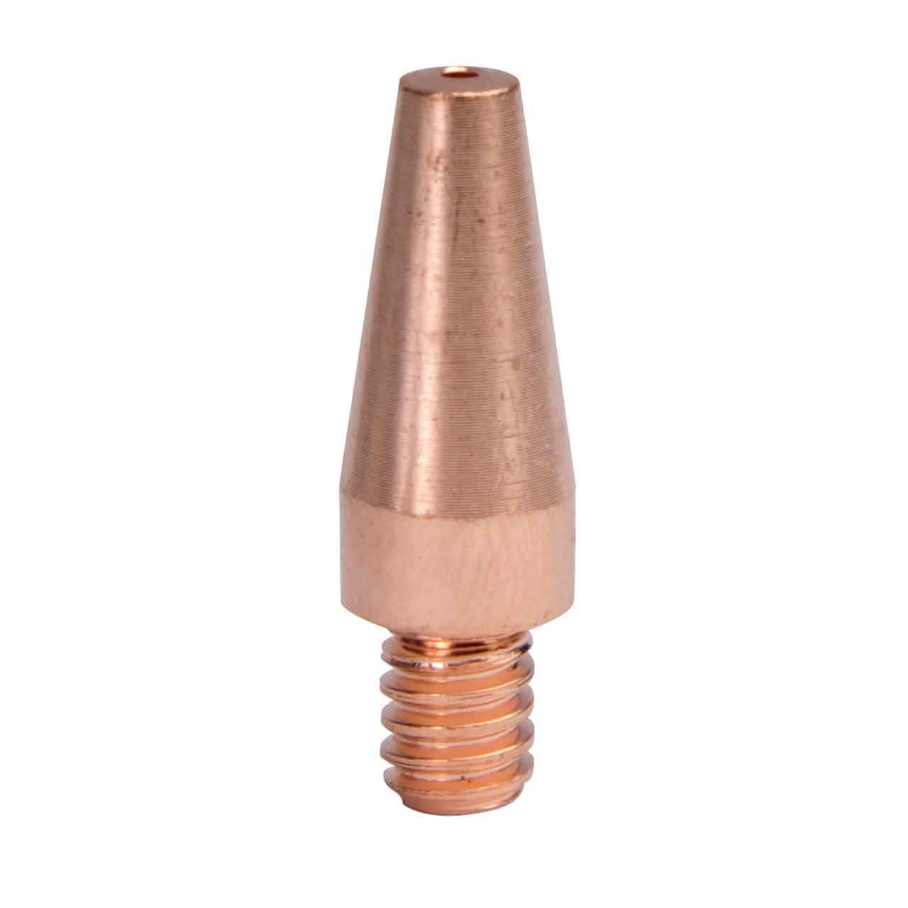
    Lincoln Electric KP2744-040T Copper Plus Contact Tip 350A .040 in (1.0 mm) Tapered, 10 pack is a MIG consumable intended for use with .040 in wire. For buyers and maintenance teams, the value of a contact tip is simple: it must transfer current consistently, match the wire size, and stay in service long enough to avoid unnecessary downtime. A worn or incorrectly sized tip can cause arc instability, erratic feeding, and tip burnback. This part is a tapered contact tip, which is commonly used where access matters and where the welding setup benefits from a narrower front end. Exact fitment and application should still be verified against the gun, liner, feeder settings, and wire specification before use.

    Key Takeaways

    • Designed for .040 in (1.0 mm) wire size.
    • Tapered profile may help access tighter joints. Exact clearances are application dependent.
    • Contact tips are wear parts. Replace them before arc quality and feeding become inconsistent.
    • Tip life depends on wire cleanliness, parameter control, duty cycle, and operator technique.
    • Final compatibility must be checked against the gun and consumable family. Unknown (Verify) if not confirmed in the equipment documentation.

    What this contact tip does

    A contact tip serves as the electrical transfer point between the wire and the power source through the gun. It also guides the wire at the last point before the arc. If the wire bore is too tight, feeding can bind. If it is too loose or worn, the arc can wander and the wire may not transfer current consistently. For a .040 in wire setup, the correct tip size is critical. Use only the size specified by the machine, gun, and wire data. Do not assume that all .040 in consumables are interchangeable across brands or gun styles.

    Practical inspection points

    Before installing the tip, inspect it and the rest of the consumable stack. A fast check can prevent repeated shutdowns.

    • Check: Confirm the wire diameter is .040 in (1.0 mm). Verify the spool label and feeder settings.
    • Inspect: Look for thread damage, deformation, or shipping damage on the tip body and end face.
    • Verify: Confirm the tip style matches the gun consumable family used on the machine. Unknown (Verify) if not documented.
    • Check: Confirm the diffuser, nozzle, and tip holder are clean and not heat damaged.
    • Inspect: Look for spatter buildup, ovalized wire bore, or discoloration from overheating on the removed tip.

    Troubleshooting support sections

    If the arc is unstable

    Start with the tip and wire path. A poor current transfer point can show up as a wandering arc, spatter increase, or inconsistent bead shape.

    • Check: Tip size against wire size.
    • Inspect: Tip bore for wear, spatter, and heat erosion.
    • Verify: Gun liner condition and drive roll pressure are set correctly.
    • Check: Work clamp contact and cable condition.

    If the wire feeds inconsistently

    A feed issue is not always a drive roll problem. The tip can be the restriction point, especially when the bore is worn, dirty, or partially blocked.

    • Check: Feed speed stability at the feeder and trigger points.
    • Inspect: Tip entrance for burrs or metal buildup.
    • Verify: The wire is not oversized, rusted, or contaminated.
    • Check: Whether the contact tip is overheat-discolored or loose in the diffuser.

    If tip life is short

    Premature wear usually points to heat load, poor wire quality, incorrect stickout, or misalignment in the consumable stack.

    • Check: Welding parameters against the application range used by your procedure.
    • Inspect: Spatter accumulation that may be trapping heat at the nozzle and tip.
    • Verify: Whether wire cleanliness and storage controls are adequate.
    • Check: Whether the tip is being changed too late, after the bore has already opened up.

    Buyer and maintenance notes

    For purchase planning, contact tips are usually stocked as routine replacement items. The main questions are not marketing related; they are practical. Does the tip match the wire? Does it match the gun family? Does it hold up long enough under the expected amperage and duty cycle? For this product, the published description identifies a 350A class tapered Copper Plus contact tip for .040 in wire. Other technical details, including exact thread style, gun compatibility, or package specifics beyond the product title, are Unknown (Verify) unless confirmed in the machine and consumable documentation.

    When building a spare-parts kit, keep the replacement process simple: one verified tip size, one verified gun family, and a clean method for checking wear. That reduces setup variation and helps maintenance teams isolate whether a weld issue is caused by the tip or somewhere else in the system.

    Product / parts section

    Use the product link below as the source product page for this consumable:

    Lincoln Electric KP2744-040T Copper Plus Contact Tip 350A .040 in (1.0 mm) Tapered, 10 pack

    Lincoln Electric KP2744-040T Copper Plus Contact Tip 350A .040 in (1.0 mm) Tapered, 10 pack

    Lincoln Electric KP2744-040T Copper Plus contact tips are tapered 350A MIG consumables sized for .040 in (1.0 mm) wire, built to deliver consistent current transfer and stable arc performance in higher-amperage applications. The tapered profile helps improve access in tighter joints while maintaining a reliable wire-to-tip interface, supporting smoother feeding and reducing downtime from premature tip wear. Suppli…

    View at Arc Weld Store

    This page should be used to confirm the current listing details before ordering or placing it into a maintenance standard. Do not assume fitment from the title alone. Verify against the gun and feeder documentation, especially if the operation uses mixed equipment brands or older torch assemblies.

    Safety notes

    • Lock out and de-energize equipment before replacing consumables where site procedure requires it.
    • Allow the gun and tip to cool before handling. Contact tips can retain heat after welding.
    • Do not force a mismatched tip into the diffuser or holder.
    • Use eye protection when removing spatter or inspecting worn consumables.
    • If a consumable repeatedly fails, stop and verify the gun, liner, and parameter settings before continuing production.

    FAQ

    Is this contact tip only for .040 in wire?

    The product title identifies .040 in (1.0 mm) wire. Use that as the primary sizing reference. Do not substitute other wire sizes without verifying the equipment documentation. Unknown (Verify) for any alternate wire sizes.

    Does the tapered profile improve performance?

    A tapered profile can help access tighter areas and may improve visibility or reach in some applications. Actual benefit depends on the torch setup, joint design, and weld position. Verify in your specific application.

    How do I know when to replace the tip?

    Replace it when the wire bore is worn, feeding becomes irregular, arc stability degrades, or heat damage becomes visible. In maintenance practice, do not wait for a complete failure if the tip is already showing wear.

    Will this tip fit every Lincoln gun?

    No. Fitment depends on the gun model and consumable family. Confirm with the equipment manual or parts list. Unknown (Verify) unless the exact gun compatibility is documented.

    Sources Checked

    • ArcWeld product page for Lincoln Electric KP2744-040T Copper Plus Contact Tip 350A .040 in (1.0 mm) Tapered, 10 pack
    • Provided internal product reference and title data
    • Allowed internal link list provided with the task

    Additional verification may be needed against the gun manual, feeder documentation, and shop procedure before release to production use.

    Related Weld Support Guides

  • Hypertherm 220955 Deflector, Pack of (1): Replacement Part Breakdown

    The Hypertherm 220955 Deflector, Pack of (1) is a replacement part used in plasma cutting support applications. For maintenance buyers and shop leads, the main job is simple: identify the part correctly, verify fit before install, and replace it before heat damage or arc quality problems spread to neighboring consumables.

    This article is a practical breakdown for troubleshooting and replacement planning. It does not assume compatibility beyond the information provided in the source record. Any machine-match details not explicitly verified here should be treated as Unknown (Verify).

    Key Takeaways

    • The part referenced here is the Hypertherm 220955 Deflector, Pack of (1), tied to ASIN B00769KWSI.
    • A deflector is a wear component. If it shows heat deformation, erosion, spatter buildup, or poor seat condition, replace it.
    • Do not assume interchangeability with other Hypertherm consumables without verifying the torch, system, and part number.
    • For any uncertain machine match, the correct status is Unknown (Verify).
    • Use this part as a maintenance replacement item, not as a substitute for confirming full consumable stack condition.

    What this part is used for

    A deflector in a plasma cutting setup helps manage torch protection and the consumable stack around the arc path. In practical terms, it is part of the consumable assembly that must withstand repeated heat exposure and contamination from cutting debris. If the deflector no longer holds shape or no longer fits cleanly, downstream performance can degrade quickly.

    Because the provided source record does not include a complete machine list, torch family, or dimensional specification, those details remain Unknown (Verify). Before ordering or installing, confirm the exact Hypertherm system, torch model, and the replacement part number on the existing component or in the OEM manual.

    How to inspect before replacement

    Use the following checks before deciding whether the part should come off the shelf and into service:

    • Check the part number. Verify that the existing deflector and the replacement both align with 220955 or the approved OEM documentation.
    • Inspect for heat damage. Look for warping, discoloration, cracking, or melted edges.
    • Inspect the seating surface. A deflector that does not seat cleanly can create alignment problems in the consumable stack.
    • Inspect for spatter and debris buildup. Heavy contamination can cause poor fit and unstable cutting behavior.
    • Verify the surrounding consumables. Nozzle, electrode, shield, and other related parts may also need attention if the deflector shows repeated failure.

    Troubleshooting support: when the deflector may be the issue

    If the torch is running poorly, do not jump straight to the deflector as the only cause. Use a step-by-step inspection path:

    • Check: Is the arc starting consistently, or is the torch hesitating on ignition?
    • Inspect: Are cut edges rougher than normal, with visible instability or excessive dross?
    • Verify: Are the torch stack-up parts installed in the correct order and fully seated?
    • Check: Is the deflector face heat-checked, eroded, or out of round?
    • Inspect: Is there evidence of blowback, spatter intrusion, or abnormal wear on neighboring consumables?
    • Verify: Is the machine operating within OEM guidance for air quality, torch setup, and cutting method? Those values are Unknown (Verify) here if not pulled from the machine manual.

    If a new deflector fails quickly, the root cause may be elsewhere: incorrect installation, contaminated air supply, damaged torch components, or a mismatch between part number and torch family. Replace only after those items are checked.

    Replacement workflow: practical check, inspect, verify steps

    1. Check lockout and cool-down. Power down the plasma system and let the torch cool before touching consumables.
    2. Inspect the removed part. Document wear pattern, discoloration, and fit condition. A good used part tells you whether the failure was normal wear or abnormal stress.
    3. Verify the replacement part number. Match the incoming part to the work order and the OEM reference before opening the package.
    4. Check the torch body and adjacent consumables. Clean out debris and confirm the stack is not damaged.
    5. Install and seat correctly. Do not force the part. If it does not seat naturally, stop and re-verify fit.
    6. Inspect after the first test cut. Watch for arc stability, abnormal noise, and early signs of overheating.

    Product and parts note

    This article is centered on one provided product reference only: Hypertherm 220955 Deflector, Pack of (1). The available product shortcode is:

    No products found.

    No other products, substitute parts, compatibility claims, or kit contents are introduced here. If the shop is comparing options, keep the evaluation limited to verified OEM documentation and the existing torch assembly record. Any compatibility beyond the named part is Unknown (Verify).

    Safety notes

    • Always de-energize plasma equipment before service.
    • Allow torch components to cool before inspection or replacement.
    • Use gloves and eye protection when handling used consumables; edges and spatter can be sharp.
    • Do not install worn parts just to finish a job. Abnormal wear can spread damage to other components.
    • If you cannot confirm fit, stop and verify against OEM documentation.

    FAQ

    Is the Hypertherm 220955 deflector a universal part?

    No. Do not treat it as universal. Compatibility is not confirmed here and should be verified against the exact torch and system documentation. If uncertain, label it Unknown (Verify).

    When should a deflector be replaced?

    Replace it when you see heat distortion, cracking, severe erosion, poor seating, or contamination that cannot be cleaned without leaving damage. If cut quality changes and the rest of the stack looks suspect, inspect all consumables before ordering another part.

    What should I check if a new deflector fails early?

    Check installation order, seating, torch cleanliness, air quality, and the condition of neighboring consumables. Also verify that the part number matches the correct torch family. If any of those points are not confirmed, the cause is still Unknown (Verify).

    Can I use this article to approve a procedure or machine setup?

    No. This is a buyer and maintenance breakdown only. It is not a procedure approval document and does not replace OEM setup guidance.

    Sources Checked

    • Provided topic record for Hypertherm 220955 Deflector, Pack of (1)
    • Provided ASIN registry reference: B00769KWSI
    • Provided product shortcode:

      No products found.

    If your next step is procurement, verify the exact torch model, confirm the part number, and document the condition of the removed deflector before closing the work order.

    Disclosure: As an Amazon Associate, Weld Support Parts may earn from qualifying purchases.

  • Thermal Dynamics 8-7503 Tip, 10 pack: Product Breakdown

    Thermal Dynamics 8-7503 Tip, 10 pack: Product Breakdown

    Product not found.
    “>Thermal Dynamics 8-7503 Tip, 10 pack

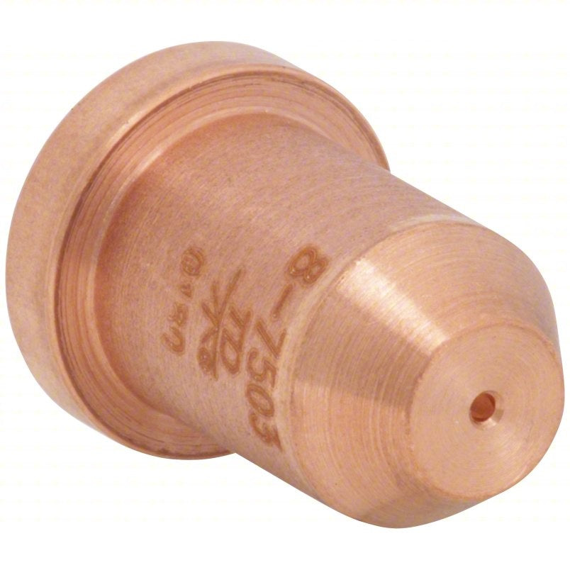
    The Thermal Dynamics 8-7503 Tip, 10 pack is a plasma cutting consumable for users maintaining compatible Thermal Dynamics systems. This part is listed for the PCH-80 torch and is described as a 40 amp tip. It is also associated with the 625XR, Cutmaster 80XL, Pakmaster 75, Pakmaster 75XL, and Signature PAK625XR. Treat those fitment notes as the starting point for verification, not a substitute for checking the torch, machine, and current consumable chart before installation.

    For maintenance buyers and shop leads, the practical question is not just whether the tip is available. The question is whether the consumable matches the torch body, the amperage setting, and the cut process you actually run. A wrong tip can cause poor arc start, unstable cut quality, excess wear, and unnecessary torch damage. Verify the part number on the old tip, the torch model, and the machine manual before you issue the replacement.

    Key Takeaways

    • Thermal Dynamics 8-7503 is a plasma tip sold in a 10-pack.
    • It is listed for the PCH-80 torch and described as a 40 amp tip.
    • Fitment is stated for 625XR, Cutmaster 80XL, Pakmaster 75, Pakmaster 75XL, and Signature PAK625XR, but you should verify against your manual and torch setup.
    • Consumable life depends on cut current, standoff, air quality, pierce practice, and operator technique.
    • If performance drops, inspect the tip first before replacing larger torch components.

    What this part is used for

    Plasma tips focus and constrict the plasma arc. In service, the tip is a wear item. When the orifice opens up, erodes, or becomes misshaped, cut quality declines. Common signs include rough edges, heavy dross, delayed arc transfer, unstable arc, and visible damage at the tip opening. If you see those symptoms, inspect the full consumable stack, not just the tip.

    Check, inspect, verify before installation

    Check the part number on the packaging and compare it to the torch consumable list. If your removed tip is readable, match the number stamped or identified by your internal records. Do not assume a similar-looking tip is correct.

    Inspect the torch lead, electrode, shield, swirl ring, retaining cap, and any related wear parts. Tip wear may be a symptom of a larger issue such as misaligned assembly, dirty air, or incorrect operating technique. Look for carbon buildup, cracks, ovalization, heat discoloration, and thread damage where applicable.

    Verify the amperage setting and cutting application. A 40 amp tip should be used only where the torch and system documentation support it. If the machine is being run above or below the intended operating range, verify the correct consumable set rather than forcing the current to match the part.

    Troubleshooting support section

    If cut quality is inconsistent, use the tip as the first checkpoint.

    • Check arc start: Verify the electrode and tip are installed correctly and that the torch is fully assembled.
    • Inspect air supply: Moisture, oil, and contamination can shorten tip life. Confirm clean, dry air at the torch input.
    • Verify standoff: Excessive drag or too much gap can accelerate wear. Use the cutting method recommended by the machine maker.
    • Check pierce technique: Aggressive piercing can blow molten material back into the consumables. Review pierce height and delay settings.
    • Inspect the tip orifice: If the opening is enlarged, out of round, or burned, replace the tip and inspect the matching electrode.

    If the same failure repeats after replacement, the root cause is likely upstream. Recheck torch assembly, air quality, power settings, and any process changes introduced before the problem started.

    Product and parts notes

    The available product information identifies this as the Thermal Dynamics 8-7503 Tip, 10 pack. It is described as a part for Thermal Dynamics PCH-80 and as a 40 amp tip. The listed compatible platforms are 625XR, Cutmaster 80XL, Pakmaster 75, Pakmaster 75XL, and Signature PAK625XR. If you are supporting mixed equipment in a maintenance crib, confirm that the torch system in service uses the same consumable family. Unknown (Verify) if your torch revision or retrofit kit changes the required tip stack.

    Because this is a consumable, the value is in repeatable fitment and replacement control. Keep the part number tied to your issue list, not just the machine name. That reduces mis-picks when multiple Thermal Dynamics systems are in the same facility.

    Support checklist for buyers and maintenance teams

    • Confirm the torch model in use.
    • Match the consumable part number to the old tip and current documentation.
    • Verify amperage before release to the floor.
    • Inspect the matching electrode and shield parts for wear.
    • Log air quality and failure mode if tips are failing early.

    Safety notes

    Plasma cutting consumables are part of an energized cutting system. De-energize the machine and allow the torch to cool before service. Do not touch used consumables without verifying temperature. Use eye, hand, and body protection when inspecting torch parts. If the torch shows repeated overheating or unusual wear, remove it from service until the cause is identified.

    FAQ

    Is the Thermal Dynamics 8-7503 Tip, 10 pack a universal plasma tip?
    No. It is listed for specific Thermal Dynamics torch systems. Verify the torch family and consumable chart before use.

    What amp rating is listed for this tip?
    It is described as a 40 amp tip. Verify that this matches your machine setup and application before installation.

    What should I inspect when a tip wears out early?
    Check the electrode, shield, swirl ring, air quality, standoff, and pierce technique. Early tip wear often points to a system issue, not just normal consumable life.

    Can I use the part number alone to confirm fitment?
    Use the part number as the first check, but also verify the torch model and machine documentation. Unknown (Verify) if your setup includes nonstandard torch revisions or retrofit components.

    Sources Checked

    • ArcWeld product page for Thermal Dynamics 8-7503 Tip, 10 pack:
      Product not found.

    Related Arc Weld Part

    Thermal Dynamics 8-7503 Tip, 10 pack

    Thermal Dynamics 8-7503 Tip, 10 pack

    For Thermal Dynamics PCH-80. 40 Amp Tip. 625XR, Cutmaster 80XL, Pakmaster 75, Pakmaster 75XL, Signature PAK625XR. Package of 10

    View at Arc Weld Store
  • Victor Thermal Dynamics 9-8211 Tip 80-Amp, Pack of (1): Product Breakdown

    Victor Thermal Dynamics 9-8211 Tip 80-Amp, Pack of (1): Product Breakdown

    Product not found.
    “>Victor Thermal Dynamics 9-8211 Tip 80-Amp, Pack of (1)

    The Victor Thermal Dynamics 9-8211 Tip 80-Amp, Pack of (1) is a plasma cutting consumable intended for use in supported torch systems. For buyers and maintenance teams, the main question is not just whether the part is available, but whether it matches the torch, current range, and operating system already in service. This breakdown focuses on practical verification steps so you can avoid fit-up issues and premature consumable wear.

    Per the provided product information, this 80-amp tip is best used on SL60 and SL100 torches. It is also described as usable on a plasma cutting torch that performs with virtually all plasma cutting power supplies. The 1Torch is listed as working with high frequency start systems, CD start systems, touch start systems, and moving parts (blow back) start systems. Verify your exact torch model and power source before ordering or installing.

    Key Takeaways

    Product and Parts Review

    This part is a plasma tip, so it should be treated as a wear item rather than a permanent component. In maintenance planning, tips are normally purchased with other consumables such as electrodes, shields, and retaining parts when applicable. The supplied product description does not list those companion parts, so do not assume a kit configuration. Confirm what your torch head actually uses.

    Before installation, inspect the new tip for obvious defects. Look for damaged threads, distortion, nicks, oval openings, or contamination from storage. If the tip appears damaged, do not install it. Keep consumables clean and dry, and store them in original packaging until needed.

    Check

    Inspect

    Verify

    Troubleshooting and Support Notes

    If the tip installs but the cut is unstable, start with the basics. Consumable issues are often caused by setup, not the part alone. Use the following checks in sequence.

    Arc starts but cut quality is poor

    Tip wear is faster than expected

    Tip will not seat correctly

    WSP Lookup Section

    No WSP lookup page was provided for this draft, so no source-based lookup link is included here. If you need a cross-reference check, use the approved WSP lookup tool available in your internal workflow before procurement.

    Buyer and Maintenance Guidance

    For buyers, the main control point is fit confirmation. An 80-amp plasma tip is only useful if it matches the torch body, consumable stack, and current setting. For maintenance teams, the better approach is to standardize by machine family and keep a small approved consumable list by torch type. That reduces installation errors and keeps replacements predictable.

    When ordering this part, confirm the exact torch model from the machine label, torch tag, or service record. Do not rely on appearance alone. Similar torches can use different consumable designs. If documentation is missing, compare the removed tip with the replacement and verify against the torch manual before use.

    Safety Notes

    FAQ

    Is the Victor Thermal Dynamics 9-8211 Tip 80-Amp compatible with SL60 and SL100 torches?

    Based on the provided product description, yes. It is listed as best used on SL60 and SL100 torches. Verify against your exact torch revision before installation.

    Can this tip be used on all plasma cutting power supplies?

    The provided description says it can be used on a plasma cutting torch that performs with virtually all plasma cutting power supplies. Do not treat that as a blanket approval. Verify your machine, torch, and start system before use.

    Does the 1Torch work with different start systems?

    The supplied information states that the 1Torch works with high frequency start systems, CD start systems, touch start systems, and moving parts (blow back) start systems. Confirm this against the exact torch model in your shop.

    What should I inspect first if cut quality drops after replacing the tip?

    Inspect the electrode, air quality, torch seating surfaces, and amperage setting first. A new tip will not correct a worn electrode, bad air, or an incorrect machine setup.

    Sources Checked

    Final note: treat this tip as a consumable matched to a specific torch family. Verify the torch model, start system, and operating setup before ordering or installing.

    Related Arc Weld Part

    Victor Thermal Dynamics 9-8211 Tip 80-Amp, Pack of (1)

    Victor Thermal Dynamics 9-8211 Tip 80-Amp, Pack of (1)

    Victor Thermal Dynamics 9-8211 Tip 80 Amp best to be used on SL60 and SL100 torches. This tip can be used on the plasma cutting torch that performs with virtually all plasma cutting power supplies. The 1Torch works with high frequency start systems, CD start systems, touch start systems and moving parts (blow back) start systems. Pack of 1 each

    View at Arc Weld Store
  • S19417 Lincoln Style Nozzle Insulator – Arc Weld by Masterweld Pack of (2): Product Breakdown

    S19417 Lincoln Style Nozzle Insulator – Arc Weld by Masterweld Pack of (2): Product Breakdown

    Product not found.
    “>S19417 Lincoln Style Nozzle Insulator - Arc Weld by Masterweld Pack of (2)

    The S19417 Lincoln Style Nozzle Insulator – Arc Weld by Masterweld Pack of (2) is a MIG support part meant for a specific torch-component stack. According to the product source, it is a Lincoln style nozzle insulator, it is used with the S19418 gas diffuser, and it does not work with PRO series equipment. That is the core buying point: this is a fitment-sensitive part, not a universal consumable.

    For welders and maintenance buyers, the practical question is not only “what is it?” but “will it match the torch setup already in service?” This article keeps the focus on verification steps, fit checks, and support-side troubleshooting before the part is installed into production use.

    Key Takeaways

    What This Part Does

    A nozzle insulator sits in the consumable stack and helps isolate and position the nozzle assembly relative to the diffuser and contact area. In practical shop use, that means the part needs to match the torch design closely. If the geometry is wrong, the nozzle may not seat correctly, or the assembly may not maintain the intended spacing.

    Because the source data only confirms the Lincoln style designation, the S19418 diffuser pairing, and the PRO series exclusion, any deeper compatibility claims are Unknown (Verify). Do not assume it will interchange with all Lincoln-pattern MIG guns or all aftermarket diffuser designs.

    Buyer Check: Before You Order

    Installation and Support Checks

    Use the following checks during replacement and return-to-service:

    If the nozzle will not seat, do not grind the insulator to make it fit. That usually indicates a mismatch in the torch system, a worn diffuser, or the wrong consumable family. Unknown (Verify) for any workaround not stated in the source.

    Troubleshooting Support

    Problem: Nozzle will not seat correctly

    Problem: Consumable life is short

    Problem: Replacements do not match the old part

    Product and Parts Notes

    This article only uses the product information supplied for the Arc Weld by Masterweld listing. The available facts are limited to the Lincoln style nozzle insulator designation, the S19418 diffuser pairing, and the PRO series limitation. No additional specs, dimensions, materials, or certifications are provided here because they were not supplied in the source data.

    If you are building a stocking plan, treat this part as a torch-specific support item. Stocking the wrong consumable family creates avoidable downtime. The quickest support check is to pull one unit from the tool crib and compare it to the torch in service before ordering multiples.

    Product reference:

    S19417 Lincoln Style Nozzle Insulator - Arc Weld by Masterweld Pack of (2)

    S19417 Lincoln Style Nozzle Insulator – Arc Weld by Masterweld Pack of (2)

    Lincoln Style Nozzle Insulator – Use with S19418 gas diffuser – Does not work with PRO series

    View at Arc Weld Store

    Related Reading

    For another consumable example and a different material category, see this internal Weld Support Parts post: Aluminum ER 5554 3/64″ X 5lb. MIG Welding Wire Spool By Washington Alloy – Weld Support Parts Blog. Use it as a reference for how filler metal content is organized, not as a compatibility guide for this nozzle insulator.

    Safety Notes

    FAQ

    Is this insulator universal across Lincoln-style MIG guns?

    No. The source only confirms Lincoln style and the S19418 diffuser pairing. Universal use is Unknown (Verify).

    Can it be used with PRO series equipment?

    No according to the product source. It states that it does not work with PRO series.

    What should I verify before ordering a replacement?

    Check the torch family, confirm the diffuser part number, compare the old part to the new part, and verify that the setup is not a PRO series unit.

    Does the listing provide material, dimensions, or certifications?

    No. Those details are not provided in the source data and should be treated as Unknown (Verify).

    Sources Checked

    Related Weld Support Guides

  • Hobart IronMan 240 MIG Welder Support: Parts Lookup and Buying Checks

    Hobart IronMan 240 MIG Welder Support: Parts Lookup and Buying Checks

    Hobart IronMan 240 MIG Welder Support

    If you support a Hobart IronMan 240 in the field or in a shop, the main risk is not the machine itself. It is ordering the wrong support part, missing a wear item, or assuming a gun, drive roll, or consumable will fit without checking the exact configuration. Use the Hobart IronMan 240 MIG Welder Support page as the first reference point, then verify the machine setup before you buy.

    This draft is built for maintenance buyers, welders, and support teams who need a practical way to confirm parts, spot common wear issues, and avoid preventable returns.

    Key Takeaways

    • Start with the dedicated Hobart IronMan 240 MIG Welder Support page for machine-specific lookup.
    • Verify the gun, wire feed components, drive rolls, and consumables before ordering anything.
    • Do not assume package contents match your exact machine setup if the unit has been modified.
    • Use support pages as a parts-checking tool, not as a substitute for the machine manual or a physical inspection.
    • If a detail is not confirmed on the source page, treat it as Unknown (Verify).

    How to Use the Hobart IronMan 240 Support Page

    The WSP lookup page is the most direct starting point for identifying support items tied to this machine. It references the Hobart IronMan 240, package contents, the HR-200 MIG gun, the SpoolRunner 200, drive rolls, and consumable part links. Those references help you narrow the search, but they do not replace an inspection of the machine you are actually servicing.

    Check: confirm the exact machine nameplate and model designation on the welder. If the label is missing or unreadable, record the serial and any visible configuration details before ordering. Inspect: look at the installed gun, feeder path, and wire size in use. A previous owner may have changed parts from the original setup. Verify: match any replacement part against the lookup page and the physical machine. If a fitment detail is not clearly confirmed, mark it Unknown (Verify) and pause the order.

    What to Review Before You Buy

    For a MIG welder support order, the parts that most often create problems are the ones that seem simple: the gun, the liner path, drive rolls, contact tips, nozzles, and spool-feed accessories. The Hobart IronMan 240 support page points to the HR-200 MIG gun and SpoolRunner 200, but you still need to confirm what is installed on the machine today.

    Check the gun setup: Look at the gun body, neck, trigger condition, and lead connection. If the installed gun is not the one listed on the support page, do not assume the same consumables will fit. Inspect the drive roll area: Open the feed compartment and look for wear, surface damage, or wire debris. Drive roll type, groove profile, and wire size must be verified against the actual configuration. Verify consumable size: Measure the wire diameter in use and check the contact tip, nozzle, and liner path against that size. If the wire size is unknown, label it Unknown (Verify) until it is confirmed.

    Troubleshooting and Support Checks

    Wire feed is inconsistent

    Check: the spool tension, feed roll pressure, wire path, and liner condition.

    Inspect: for dust, rust, sharp bends in the lead, and worn drive rolls.

    Verify: the wire is the correct diameter for the installed drive roll and tip. If the current wire type is not documented, mark it Unknown (Verify).

    Arc starts poorly or burns back

    Check: the contact tip condition and whether the tip matches the wire size.

    Inspect: the nozzle, diffuser area, and accumulated spatter.

    Verify: the gun and consumables listed on the support page match what is actually installed.

    SpoolRunner support appears different from expected

    Check: the accessory mount, connection points, and any added adapters.

    Inspect: the feed path and cable routing for pinch points or damage.

    Verify: the exact SpoolRunner 200 setup before ordering support parts. If the current accessory is not confirmed, treat compatibility as Unknown (Verify).

    WSP Lookup Reference

    Use the dedicated machine page here: Hobart IronMan 240 MIG Welder Support.

    This is the correct starting point for part lookup because it ties the machine to listed support references such as the HR-200 MIG gun, SpoolRunner 200, drive rolls, and consumable links. Use it to narrow the parts search, then verify the actual installed configuration before purchase.

    Buying Checks for Maintenance Teams

    Before submitting a purchase order, run a short review:

    1. Confirm the machine ID. Match the Hobart IronMan 240 label and note any configuration changes.
    2. Record the installed gun. Compare the current gun to the HR-200 MIG gun reference on the support page.
    3. Check wire feed components. Inspect drive rolls, tension settings, and liner condition.
    4. Confirm consumables. Verify tip, nozzle, and related wear items against the current wire size.
    5. Document unknowns. Anything not confirmed should remain Unknown (Verify) until checked in person.

    Safety Notes

    • De-energize the machine before opening covers or touching internal feed components.
    • Use lockout/tagout where required by site procedure.
    • Do not inspect drive rolls or gun components with the feeder live.
    • Wear eye protection when checking for spatter, wire fragments, or damaged consumables.
    • Replace damaged cables, connectors, or worn consumables before returning the unit to service.

    FAQ

    Can I order parts from the support page without checking the machine first?

    You can start there, but you should not finish there. Confirm the machine label, installed gun, wire size, and feed components before ordering.

    Does the support page guarantee the exact parts I need?

    No. It provides a machine-specific starting point. Final fitment still depends on the installed configuration, which may differ from the original package.

    What if the wire size or gun model is not clear?

    Treat that detail as Unknown (Verify). Measure the wire and inspect the gun and feed path before selecting a replacement.

    Are the listed accessories always original to the machine?

    Not necessarily. Support pages can reflect a standard configuration, but a used or modified machine may have different parts installed.

    Sources Checked

    Additional allowed sources in this task: none.

    Disclosure: As an Amazon Associate, Weld Support Parts may earn from qualifying purchases.
    Related Weld Support Guides

  • Hobart Handler 210MVP MIG Welder Support: Parts Lookup and Buying Checks

    Hobart Handler 210MVP MIG Welder Support: Parts Lookup and Buying Checks

    Hobart Handler 210MVP MIG Welder Support

    The Hobart Handler 210MVP is a common buyer-support case because the machine can be configured with different input power, gun setups, wire feed parts, and consumables. Before ordering replacement items, verify the machine nameplate, existing gun, wire type, and drive roll setup. This guide is built as a parts-lookup and ordering-check reference, not a substitute for the manufacturer manual or the WSP support page.

    Key Takeaways

    • Confirm the exact machine model as Hobart Handler 210MVP before comparing parts.
    • Check whether the machine is running the HR-100 MIG gun, the SpoolRunner 100, or another setup.
    • Verify wire diameter, drive roll groove, liner condition, and tip size before buying consumables.
    • Use the WSP support page as the starting point for machine-linked parts, then confirm against the machine in hand.
    • For filler wire decisions, use selection guides as a starting point only; procedure approval still depends on the job, base metal, and code or supervisor requirements.

    What to Check Before Ordering

    Buyer mistakes usually happen when one of four things is assumed instead of verified: gun type, wire size, drive roll type, or power-input configuration. Do a physical inspection first.

    • Check the nameplate: verify the exact model designation and serial information. If the label is missing or damaged, note Unknown (Verify).
    • Inspect the gun connection: confirm whether the machine currently uses the HR-100 MIG gun or a SpoolRunner 100 setup. Do not assume based on appearance alone.
    • Inspect drive rolls: read the roll marking if present and match it to the wire size in use. If unreadable, record Unknown (Verify).
    • Verify liner condition: look for drag, birdnesting, feeding noise, and excessive wire shavings.
    • Verify tip wear: oversized or burned tips can create arc instability and wire feed problems.

    Troubleshooting and Support Checks

    Wire feeds poorly

    • Check the spool brake tension.
    • Inspect drive roll pressure. Too much pressure can deform wire; too little can slip.
    • Verify the drive roll groove matches the wire type and diameter.
    • Inspect the liner for debris, kinks, or wear.
    • Verify the contact tip size and replace if the wire binds or the opening is visibly enlarged.

    Arc starts inconsistently

    • Check the work clamp connection and cable condition.
    • Inspect the contact tip for spatter buildup.
    • Verify that the wire type matches the intended application.
    • Confirm shielding gas flow if gas-shielded welding is being used.

    Unexpected burnback or tip wear

    • Verify wire feed speed and voltage settings against the job setup.
    • Check for a blocked liner, damaged tip, or incorrect standoff.
    • Inspect the gun cable for heat damage or tight bends.

    WSP Lookup Section

    Use the WSP support page here as the primary machine-linked reference for the Hobart Handler 210MVP: Hobart Handler 210MVP MIG Welder Support.

    This page is the best first stop for checking the supported machine context, package contents, and linked support items such as the HR-100 MIG gun, SpoolRunner 100, drive rolls, and consumable part links. Treat those links as a parts-check starting point. Always verify the item against the machine on your bench before ordering.

    When a detail is not clearly confirmed on the support page or on the machine itself, mark it Unknown (Verify) rather than guessing. That includes connector style, liner length, drive roll marking, and any accessory bundle details not visible on the unit.

    Buying Checks for Maintenance Teams

    If you are buying for a shop, the safest process is to work from the machine in hand and not from memory. Use this sequence:

    1. Confirm the machine model and record the serial or asset tag.
    2. Check the installed gun and wire feeder arrangement.
    3. Measure the wire diameter currently in use.
    4. Inspect the drive roll style and groove size.
    5. Verify the tip size, liner condition, and any wear parts that are being replaced.
    6. Match the replacement item to the WSP support page or linked consumable reference.

    If the job is production-critical, order a spare tip, liner, and the correct drive roll set only after verification. Do not combine guesswork with a shutdown window.

    Filler Metal and Wire Selection Notes

    No filler metal finder page was provided for this topic. If you are selecting wire, use the WSP support page and the manufacturer or filler metal references as starting points only. A selection page does not guarantee procedure approval, code compliance, or suitability for every base metal and joint design.

    For aluminum, stainless, and mild steel wire decisions, the final choice still depends on base metal, shielding gas, transfer mode, and the weld procedure in use. If any of those inputs are not confirmed, label them Unknown (Verify) before purchase.

    Safety Notes

    • Lock out or disconnect power before opening covers or touching internal components.
    • Do not inspect the gun or drive rolls with the machine energized.
    • Use eye protection when checking wire feed, liners, tips, or spatter buildup.
    • Verify shielding gas cylinder handling and secure storage before moving the machine.
    • If you find heat damage, melted insulation, or a damaged cable, remove the unit from service until repaired.

    FAQ

    How do I know which parts fit my Hobart Handler 210MVP?

    Start with the machine nameplate and the WSP support page. Then inspect the installed gun, drive roll marking, wire size, and liner condition. If any detail is unclear, record it as Unknown (Verify).

    Can I order consumables based only on the product page photo?

    No. Photos are useful for orientation, but they are not enough to confirm fitment. Verify the part against the machine, the installed gun, and the existing wear item before ordering.

    Is the WSP page a replacement for the Hobart manual?

    No. Use it as a support and parts-lookup starting point. The manual and machine inspection remain the final reference for setup, service, and safe operation.

    What should I do if the machine has mixed or uncertain accessories?

    Stop and verify each accessory separately: gun, drive roll, liner, tip, and wire. If the current configuration cannot be confirmed, do not assume compatibility.

    Sources Checked

    Disclosure: As an Amazon Associate, Weld Support Parts may earn from qualifying purchases.

    Related Weld Support Guides

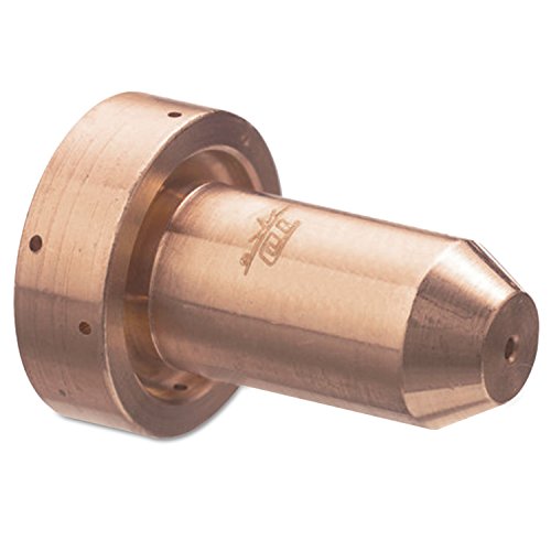
  • Hypertherm 220990, 105 Amp Nozzles for Powermax 105, Pack of (5): Replacement Part Breakdown

    Hypertherm 220990 is a consumable replacement nozzle pack listed for Powermax 105 use. For buyers and maintenance teams, the main job is not just ordering the part; it is confirming that the nozzle match is correct for the torch, amperage setting, and current wear condition. Consumables fail in ways that affect cut quality fast, so replacement decisions should be based on inspection, not guesswork.

    This guide breaks down what to check before you buy, how to inspect the nozzle stack after shutdown, and how to troubleshoot the symptoms that usually point to nozzle wear or mismatch. Product details beyond the listing itself are marked Unknown (Verify) when not confirmed.

    Key Takeaways

    • Hypertherm 220990 is listed as a 105 amp nozzle pack for Powermax 105 use.
    • Consumable replacement should follow visual inspection and cut-quality symptoms, not only runtime.
    • Check the full torch consumable stack, not just the nozzle, before ordering parts.
    • If fitment, torch family, or amperage is not confirmed, use Unknown (Verify) until verified by the equipment manual or parts list.
    • Use the Amazon product box below as a buying reference only; do not assume compatibility beyond the listing title.

    What this part is for

    The listing identifies this item as a nozzle replacement pack for a Hypertherm Powermax 105 system. In plasma cutting, the nozzle controls the constricted arc as it exits the torch. When the nozzle wears, the arc can lose focus and the cut can become wider, rougher, or less stable. That is why nozzle replacement is part of routine torch maintenance.

    Do not assume this nozzle is interchangeable with other amperage ratings or other Powermax models unless you verify the torch manual, the OEM parts list, or the markings on the existing consumables. If the exact torch or cartridge arrangement is not confirmed, mark it Unknown (Verify).

    Check before you order

    1. Inspect the torch model. Verify the machine and torch are actually Powermax 105 compatible.
    2. Check the nozzle rating. Confirm the current nozzle is a 105 amp nozzle, not a different amp class.
    3. Inspect the consumable stack. Look at the nozzle, electrode, swirl ring, shield, retaining cap, and any retaining hardware.
    4. Verify the wear pattern. Excessive pit formation, ovality, meltback, or arc instability suggests replacement is due.
    5. Confirm count and pack size. The product title shows a pack of five; verify that is what you need for stock or service planning.

    Troubleshooting: when to suspect nozzle wear

    If cut quality changes, the nozzle may be the cause, but it is not the only cause. Use a simple inspection sequence.

    Check

    • Check for a wider-than-normal kerf.
    • Check for heavy dross that appears suddenly after a period of normal cutting.
    • Check for an unstable arc or frequent arc transfer problems.
    • Check for visible heat damage on the nozzle or adjacent consumables.

    Inspect

    • Inspect the nozzle orifice for distortion, enlargement, or meltback.
    • Inspect the electrode for wear; a new nozzle with a worn electrode can still cut poorly.
    • Inspect the shield and swirl ring for contamination, cracking, or heat damage.
    • Inspect the torch body and retaining parts for debris, looseness, or damaged threads.

    Verify

    • Verify the amperage setting matches the consumable rating.
    • Verify the air supply is clean and dry.
    • Verify the torch assembly is seated correctly.
    • Verify the part number against the OEM parts list before stocking replacements.

    If the cut problem remains after replacing the nozzle, the issue may be elsewhere in the stack or in system setup. In that case, the nozzle is not the sole corrective action.

    Replacement support notes for maintenance buyers

    For shops that keep consumables on hand, part control matters. Separate nozzles by torch model and amperage class. Do not mix open stock between similar-looking plasma parts. A correct-looking nozzle with the wrong internal geometry can create false confidence and waste labor time.

    When you receive replacement parts, compare them against the old part before installation. Match the outside dimensions, contact surfaces, and visible openings as far as the OEM design allows. If any feature is unclear, treat it as Unknown (Verify) and stop before installation.

    Product / parts reference

    Hypertherm 220990, 105 Amp Nozzles for Powermax 105, Pack of (5)

    Amazon product reference:

    No products found.

    Use this as the identified replacement listing only. Do not infer additional specifications, certifications, or machine compatibility beyond the product title unless you verify them from the OEM documentation.

    Safety notes

    • De-energize the plasma system before any consumable inspection or replacement.
    • Allow the torch and consumables to cool before handling.
    • Use eye protection and gloves when inspecting used plasma consumables.
    • Do not install damaged parts just to finish a job; damaged consumables can worsen cut quality and increase torch wear.
    • Keep compressed air and debris away from the work area during maintenance.

    FAQ

    Is this nozzle pack confirmed for every Powermax 105 torch?

    No. The listing title says it is for Powermax 105 use, but exact torch and configuration compatibility should still be verified against the OEM parts list. If unconfirmed, mark it Unknown (Verify).

    Can I replace only the nozzle if cut quality drops?

    Sometimes, but not always. Inspect the electrode, swirl ring, shield, and retaining parts as a set. A fresh nozzle will not fix damage or contamination in the rest of the consumable stack.

    What is the fastest way to tell if the nozzle is worn out?

    Look for visible orifice distortion, heat damage, or a cut that suddenly becomes wider and less stable. Then verify the amperage setting and air quality before ordering parts.

    Should I stock this part without testing the torch first?

    Only if your equipment records already confirm the torch model and consumable class. If not, verify the machine and torch details before putting the part into stock.

    Sources Checked

    • Provided Amazon product reference for ASIN B00KCPSYGA via allowed product shortcode
    • Internal project brief and topic metadata

    Note: No WSP lookup page or filler metal finder page was provided for this task, so no such internal links were added.

    Matched Replacement Option

    No products found.

    Disclosure: As an Amazon Associate, Weld Support Parts may earn from qualifying purchases.
    Related Weld Support Guides

  • Hobart Handler 140EZ MIG Welder Support: Parts Lookup and Buying Checks

    Hobart Handler 140EZ MIG Welder Support: Parts Lookup and Buying Checks

    Hobart Handler 140EZ MIG Welder Support

    The Hobart Handler 140EZ is a compact MIG setup, but support work still comes down to the same basics: confirm the machine variant, identify the gun and feeder parts you actually have, and verify consumable fit before placing an order. This guide is built for buyers, maintenance techs, and welders who need to replace worn items without guessing.

    Key Takeaways

    • Start with the machine support page before you buy parts or consumables.
    • Verify gun type, drive roll style, wire size, and contact tip fit before ordering.
    • Do not assume the package contents match a unit that has been modified in service.
    • Use filler metal pages as a selection starting point, not as a guarantee of procedure approval.
    • If a compatibility point is not confirmed on the support page, mark it as Unknown (Verify).

    What to Check on a Hobart Handler 140EZ Before Ordering Parts

    Before you order anything, inspect the machine as it sits in the shop. A unit that has been in service may have a different gun, cable length, liner, drive roll, or wire path than the original package. That affects what will fit.

    Check

    • Confirm the exact machine model on the nameplate.
    • Inspect the gun and cable for wear, cuts, heat damage, or a loose neck connection.
    • Look at the drive rolls and note the wire size marking if present.
    • Verify the installed contact tip size and thread style before buying replacements.
    • Check the wire spool size and wire type currently in use.

    Inspect

    • Feed path: look for dust, liner wear, or birdnesting signs.
    • Contact tip: check for arc instability, oval wear, or spatter buildup.
    • Nozzle: inspect for spatter closure, heat distortion, or missing insulator parts.
    • Drive system: verify whether the roll surface matches the wire you run.

    Verify

    • Confirm whether the installed gun is the HM-100 MIG gun referenced on the support page.
    • Verify whether the unit uses a SpoolRunner 150 arrangement or a standard feeder setup, if applicable to your machine. Unknown (Verify) if not confirmed by the support page or machine inspection.
    • Verify the wire diameter you intend to run before ordering tips, liners, or rolls.

    WSP Lookup: Hobart Handler 140EZ Support Page

    The primary starting point for this model is the Weld Support Parts support page here: Hobart Handler 140EZ MIG Welder Support.

    Use that page to review the model-specific support notes, listed package contents, and the consumable and accessory references tied to the Hobart Handler 140EZ. The page also references the HM-100 MIG gun, the SpoolRunner 150, drive rolls, and consumable part links. If a part or configuration is not explicitly confirmed there, treat it as Unknown (Verify).

    Practical buying check: compare the support page against your machine in the shop. If the machine has been repaired, upgraded, or altered, do not rely on memory or a prior invoice. Check the machine first, then match the part family.

    Troubleshooting Support: Common Ordering Mistakes to Avoid

    Most support problems happen before the order is placed. The wrong consumable or gun component may still look close enough to fit, but a close visual match is not enough.

    Check for these issues

    • Wrong wire diameter selected for tips and drive rolls.
    • Wrong gun family selected after a previous service swap.
    • Mixed consumable parts from different setups.
    • Assuming package contents are still original after ownership changes.
    • Replacing the liner or tip without checking the feeder condition.

    Inspect, then verify

    • Inspect the tip seat: confirm whether the existing tip threads or seats match the replacement part you plan to order.
    • Inspect the roll grooves: look for wear or polishing that suggests the roll has been used with a different wire size.
    • Verify the liner length and routing: if the gun cable has been replaced or shortened, liner fit may not match the original configuration. Unknown (Verify) if not documented.
    • Verify the consumable family: use the support page references, not guesswork from a similar Hobart machine.

    Drive Rolls, Tips, and Gun Parts: What to Match

    For a MIG feeder, the most common replacement items are drive rolls, contact tips, nozzles, liners, and the gun itself. Matching starts with the wire and ends with the feeder hardware.

    • Drive rolls: match roll type to wire type and wire size as confirmed on the machine.
    • Contact tips: match the tip to wire diameter and the correct gun family.
    • Nozzles and insulators: match the gun assembly shown on the support page or on the installed gun.
    • Liners: verify liner style and length before purchase. Unknown (Verify) if the machine has been modified.
    • Gun assembly: confirm whether you need the HM-100 MIG gun or another setup before ordering.

    Filler Metal Finder: Use It as a Starting Point

    If you are also selecting wire, use the Weld Support Parts filler metal content and wire selection resources as a starting point, not as a final approval document. A useful reference is this internal guide: Best MIG Wire for Stainless Steel (ER308L vs ER309L).

    That page helps frame selection decisions, but it does not replace procedure approval, WPS requirements, or base-metal review. For any production job, verify the required wire classification, shielding gas, and procedure requirements against your shop documentation. Unknown (Verify) if not documented.

    Buying Checks for Maintenance and Purchasing

    • Match the support page to the machine serial/model label.
    • Confirm whether the current gun and feeder parts are original or field-replaced.
    • Order by verified wire size and gun family, not by appearance.
    • Keep a record of the installed consumable part numbers after replacement.
    • When in doubt, stop and verify before opening the package for install.

    Safety Notes

    • Disconnect input power before inspection or part replacement.
    • Let the gun and nozzle cool before handling after welding.
    • Wear eye protection when checking the wire path, drive rolls, or contact tip area.
    • Do not run damaged gun cables, cracked nozzles, or worn liners in service.
    • Use the correct PPE and follow your shop lockout practices.

    FAQ

    How do I know which parts fit the Hobart Handler 140EZ?

    Start with the dedicated WSP support page for the model, then inspect the machine in the shop. Match the gun, consumables, and drive components to what is installed. If the part family is not confirmed, treat it as Unknown (Verify).

    Can I buy consumables based only on the model name?

    No. The model name is a starting point, not enough by itself. Confirm wire size, gun type, and the actual feeder setup before ordering tips, rolls, or liners.

    Is the SpoolRunner 150 definitely part of every Hobart Handler 140EZ package?

    No. The support page references the SpoolRunner 150, but package contents can vary by listing, revision, or prior modification. Verify the installed configuration before purchase.

    Can I use filler metal pages to approve a production weld procedure?

    No. Use filler metal pages to narrow down likely wire options only. Final approval must come from your WPS, procedure documents, or engineering requirements.

    Sources Checked

    All uncertain technical details should be verified against the machine in service and the referenced support page before ordering.

    Disclosure: As an Amazon Associate, Weld Support Parts may earn from qualifying purchases.

    Related Weld Support Guides

  • Stream with Amazon Music