
Hypertherm 220674 Plasma Cutting Shield – T45v Hand Cutting Shield, 1 Pack
$26.50
In Stock
View Product
$26.50
In Stock
View Product
A beveled edge on a plasma cut usually means the arc is not centered through the kerf. The most common causes are torch angle, travel speed, worn consumables, incorrect standoff, and poor air quality. Start with the cut setup, then inspect parts, then check the air system.
Hold the torch square to the plate. Even a small tilt can create a bevel on one side of the cut. If the torch is hand-held, watch for side lean during the full cut path, especially on long cuts and corners.
Travel speed affects kerf shape. If you move too fast, the arc trails and the cut leans. If you move too slow, the arc can wash out the lower edge and increase dross. Make one change at a time and test on scrap.
Worn or damaged consumables can make the arc unstable. Check the electrode, nozzle, and shield for erosion, pitting, heat damage, or clogging. If the shield is damaged or worn, replace it before continuing. The Hypertherm 220674 Plasma Cutting Shield is one available part for compatible T45v hand cutting setups; exact compatibility beyond the listed product title is Unknown (Verify).
If standoff is too high, the arc can spread and lose cut squareness. If the torch is dragging when it should not, the shield or tip condition may be affecting arc control. Follow the machine or torch manual for the correct stand-off method.
Moisture, oil, and debris in the air line can cause rough cuts and edge angle changes. Drain the compressor tank, inspect filters, and confirm the air supply is clean and dry. Air pressure and flow requirements are torch-specific and Unknown (Verify) without the machine manual.
Hypertherm 220674 Plasma Cutting Shield – T45v Hand Cutting Shield, 1 Pack
This shield may be used when the existing shield is worn or damaged. Use only if it matches the torch setup and manual requirements. Compatibility details beyond the product title are Unknown (Verify).
Introducing the Hypertherm 220674 Hand Cutting Shield, your essential companion for plasma cutting tasks. This high-quality plasma cutting shield is designed to protect both your workspace and yourself. Made by Hypertherm, a trusted name in plasma cutting technology, this product ensures superior performance and durability. The Hypertherm Hand Cutting Shield is perfect for both professionals and DIY enthusiasts. I…
View at Arc Weld StoreIt usually happens when the arc is not centered through the cut path. Torch angle, travel speed, consumable wear, and air quality are the main checks.
Yes. Wet or contaminated air can make the arc unstable and change edge angle.
If the shield is worn, damaged, or heat-affected, replace it. If the shield looks normal, check nozzle, electrode, torch angle, and air supply before replacing more parts.
Start with torch angle and travel speed, then inspect consumables. Exact cut settings are torch and material dependent and Unknown (Verify) without the manual.
$26.50
In Stock
View Product
If a plasma cutter is not piercing cleanly, the usual cause is a setup problem rather than a major machine fault. Start with air quality, consumable condition, ground connection, torch angle, and pierce technique. Small errors in any of these areas can leave a ragged start, excessive dross, or a failed pierce.
Plasma cutting depends on clean, dry, correctly regulated air. Low pressure can produce a weak, unstable arc. Water, oil, or heavy contamination can cause sputtering and poor pierce quality.
Worn or damaged consumables are a common reason a plasma cutter is not piercing cleanly. The electrode and nozzle must be in good condition for a focused arc.
Poor work return can make the arc start erratically and cause a messy pierce. The clamp must make solid metal-to-metal contact on clean material.
If the torch is too close, molten metal can blow back into the shield and nozzle. If it is too high, the arc can spread and fail to pierce cleanly.
Thick plate, rusty plate, painted plate, and galvanized material can make piercing harder. Start with a clean spot if possible. If the plate is thick, give the arc enough time to fully transfer before moving.
If air, consumables, and grounding are correct but the pierce still fails, inspect the torch body, leads, and machine output for damage. Intermittent cable faults, heat damage, or loose connectors can reduce performance.
When consumables or shielding parts are worn, replace them with the correct torch parts. For hand cutting shield support, see:
Introducing the Hypertherm 220674 Hand Cutting Shield, your essential companion for plasma cutting tasks. This high-quality plasma cutting shield is designed to protect both your workspace and yourself. Made by Hypertherm, a trusted name in plasma cutting technology, this product ensures superior performance and durability. The Hypertherm Hand Cutting Shield is perfect for both professionals and DIY enthusiasts. I…
View at Arc Weld StoreHypertherm 220674 Plasma Cutting Shield – T45v Hand Cutting Shield, 1 Pack
Use only if it matches the torch model and application. Compatibility for your machine is Unknown (Verify) unless confirmed by the torch manual or parts list.
Most often it is low air pressure, contaminated air, worn consumables, or poor ground contact.
Yes. A damaged or incorrect shield can affect arc focus and increase spatter. Verify the correct shield for the torch model.
Only if the torch and process are designed for drag operation. Otherwise, maintain the correct standoff distance and start upright. Unknown (Verify).
Check air pressure, replace visibly worn consumables, and clean the ground point. Those three checks solve many start-up problems.

If an exothermic cutting rod will not stay lit, start with oxygen delivery, rod condition, and starting technique. Most ignition problems come from inconsistent gas flow, a worn consumable, or a poor start angle.
When an exothermic cutting rod not staying lit becomes repeatable, work through the setup in order. Do not change multiple variables at once.
Use a steady oxygen supply. Low flow, blocked passages, or rapid trigger changes can extinguish the cut as soon as the rod tries to establish the burn. Confirm the oxygen valve, hose, and torch path are open and operating normally.
Rod condition matters. A rod that is damp, bent, damaged, or contaminated may not stay lit. Store consumables dry and handle them cleanly. If the rod coating or end condition looks abnormal, discard it and try a new rod.
The rod needs a clean, deliberate start. Hold the correct position, strike consistently, and keep the oxygen engaged as required by the process. If the rod is lifted too soon or the start is inconsistent, the burn can drop out.
Make sure the torch, consumable, and conversion hardware match the process being used. If the system has been modified, compatibility is Unknown (Verify) until confirmed by the equipment documentation.
Restricted flow, damaged seals, or worn internal components can interrupt oxygen delivery. Inspect the torch and related parts for damage, dirt, or blockage.
If you are troubleshooting a persistent ignition problem and the setup uses compatible Arcair hardware, the related support article may help compare symptoms and causes.
For conversion-related setup checks, one available part is:
Product link:
Introducing the Arcair 94-463-032, Slice 3/8" Conversion Kit, an essential addition to your cutting tool arsenal. This conversion kit is designed to enhance the performance of your existing cutting equipment, ensuring precision and efficiency in your cutting tasks. The Arcair 94-463-032 is specifically engineered to fit seamlessly with compatible models, providing a reliable solution for your cutting needs. Whethe…
View at Arc Weld StoreCommon causes are weak oxygen flow, poor starting technique, or a rod that is damp or damaged.
No. If ignition remains unstable, replace the rod and inspect the torch setup. Repeated failed starts can indicate contamination or a supply problem.
Check oxygen delivery first, then test with a fresh rod. That sequence helps isolate the fault faster.
No. The conversion kit is a hardware option, not a diagnosis. Use it only if the system compatibility is confirmed. Otherwise, compatibility is Unknown (Verify).
If you are dealing with tig torch overheating, treat it as a setup or duty-cycle problem first. Excess heat at the torch can damage the body, burn consumables, and reduce shielding gas performance. The cause is usually current demand, poor cooling, loose connections, restricted gas flow, or a torch body that is not suited to the job.
Running more current than the torch can handle will build heat quickly. This is the first item to check when the handle, head, or cable becomes uncomfortable to touch during normal welding intervals. If the torch is near its limit, reduce amperage or move to a torch body designed for the job. Exact duty-cycle limits for your setup are Unknown (Verify).
Internal wear, loose fittings, or heat damage can make the torch run hotter than normal. Inspect the body for cracking, loose head alignment, damaged insulators, and signs of prior overheating. If the torch body has been degraded, repair or replacement is the correct fix, not higher gas flow or a larger cup alone.
Loose collet bodies, worn consumables, dirty threads, and poor connections in the power path can add resistance and create local heat. Clean and tighten all serviceable joints. Replace parts that no longer hold properly.
Restricted gas flow, leaks, or a damaged cup can force longer arc time and higher heat input at the torch. Check the gas line, fittings, regulator, and nozzle area for leaks or blockage. If the gas stream is unstable, the arc can become harder to control and increase torch load.
A tight bend, twisted lead, or cable dragged across hot work can raise torch temperature and reduce performance. Route the torch lead with a smooth bend radius and keep it away from direct contact with hot metal. If the cable insulation is damaged, remove the torch from service.
Even a torch that is correctly sized can overheat if it is used beyond its intended duty cycle. Shorten arc time, add cool-down breaks, or shift to a torch setup that is better matched to the amperage and joint size. Published duty-cycle data for the exact setup is Unknown (Verify).
If the torch body itself is the weak point, replacing it can solve recurring heat problems better than swapping consumables repeatedly. For a rigid air-cooled option, one available part is the Weldtec WT-26 Rigid Torch Body, 200A Air Cooled, 70 Degree Head for Reliable Welding.
This part is provided through the allowed ArcWeld product link:

Introducing the Weldtec WT-26 Torch Body, a top-tier choice for professionals in need of a reliable and durable welding solution. Designed for use with gas and capable of handling up to 200 amps, this rigid torch body ensures exceptional performance in a variety of applications. The WT-26 features a standard 70-degree head, which allows for increased maneuverability and accessibility in tight spaces. With its air-…
View at Arc Weld StoreUse this only if it matches your torch family and welding setup. Exact compatibility with your machine, leads, and gas setup is Unknown (Verify).
Common causes are high amperage, poor duty-cycle management, worn parts, loose connections, restricted gas flow, or a torch body that is not suited to the application.
Yes, indirectly. A poor tungsten setup can make the arc unstable and increase heat load on the torch and consumables.
If the torch body is cracked, loose, or repeatedly overheating under normal use, replacement may be the better option. If the issue is worn consumables or loose fittings, start there first.
Unknown (Verify). Match the torch body to your amperage, process, lead configuration, and machine requirements before ordering.
Introducing the Weldtec WT-26 Torch Body, a top-tier choice for professionals in need of a reliable and durable welding solution. Designed for use with gas and capable of handling up to 200 amps, this rigid torch body ensures exceptional performance in a variety of applications. The WT-26 features a standard 70-degree head, which allows for increased maneuverability and accessibility in tight spaces. With its air-…
View at Arc Weld StoreA plasma cutter that fails to cut through material typically indicates issues with air supply, consumables, or machine setup. This problem reduces cut quality, increases dross, and can damage the torch if ignored. Diagnosing the root cause quickly restores performance and prevents unnecessary wear.
Plasma cutting relies on a high-temperature ionized gas stream to melt and eject metal. When any part of the system—air supply, power, or consumables—is compromised, the arc loses effectiveness. This results in incomplete cuts, excessive slag, or arc instability.
| Cause | Symptom | Impact | Fix |
|---|---|---|---|
| Low Air Pressure | Weak arc | No full cut-through | Increase pressure |
| Worn Consumables | Wide arc | Poor cut quality | Replace parts |
| Moisture in Air | Arc sputtering | Inconsistent cuts | Dry air supply |
| Low Amperage | Slow cutting | Incomplete penetration | Increase output |
Follow ANSI Z49.1 safety standards for plasma cutting. Ensure proper grounding and use appropriate PPE including eye protection and gloves. Never operate a plasma cutter with damaged consumables or unstable air supply.
This is usually caused by low air pressure, worn consumables, or incorrect amperage settings.
Yes. Moisture or oil in the air supply disrupts the plasma arc and reduces cutting efficiency.
Replacement depends on usage and material, but worn consumables should be changed as soon as cut quality declines.
Check air supply quality and consumable condition before the next cut. Adjust settings based on material thickness and confirm stable operation on scrap material.
A plasma cutter that fails to pierce metal will produce arc instability, excessive spatter, or no full penetration. This issue is typically related to air supply, consumable wear, or incorrect setup parameters. Identifying the restriction point in the system is critical for restoring proper cut initiation.
Plasma cutting relies on a high-velocity ionized gas stream to melt and eject metal. When the system cannot pierce, the arc may start but fail to transfer enough energy into the material. This results in surface gouging instead of a full cut-through.
| Issue | Symptom | Correction |
|---|---|---|
| Low Air Pressure | Weak arc, no penetration | Increase PSI/CFM |
| Worn Consumables | Wide arc, spatter | Replace electrode/nozzle |
| Moisture in Air | Arc instability | Add dryer/filter |
| Incorrect Settings | Incomplete pierce | Adjust amperage |
Follow ANSI Z49.1 for safe cutting practices. Ensure proper ventilation and use appropriate eye and face protection rated for plasma cutting. Disconnect power before servicing consumables or air systems.
The material may exceed the machine’s rated pierce capacity or settings may be too low.
Yes. Low pressure reduces arc force and prevents molten metal from being expelled.
Replace when wear is visible or cut quality declines. Frequency depends on usage and material.
Check air supply and inspect consumables before the next cut. Correct setup and maintenance resolve most piercing failures without equipment changes.
Your MIG welder sputters, pops, or cuts out mid-weld. The arc is unstable, the weld looks rough, and you’re losing time troubleshooting. This guide walks you through the most common causes—and how to fix each one in under 30 minutes.
What you’ll see:
Most likely causes (ranked by frequency):
Step 1: Inspect the Contact Tip (Free)
Step 2: Clean the Nozzle (Free)
Step 3: Check Your Ground Clamp (Free)
Step 4: Verify Wire Speed and Voltage (Free)
Step 5: Check Gas Flow Rate (Free)
Step 6: Inspect the Gun Liner (Free)
Option 1: Adjustment (Free)
Option 2: Replace Contact Tip (~$5–$15)
Option 3: Replace Gun Liner (~$15–$40)
Option 4: Equipment Upgrade (if applicable)
A worn contact tip is the #1 cause of sputtering. Copper tips wear down with every weld—the arc erodes the tapered point, creating a flat or pitted surface. Once worn, the tip can’t deliver consistent electrical contact to the wire, and your arc becomes unstable.
Why this works:
When to use it:
When NOT to use it:
What to check before buying:

Last update on 2026-06-20 / Affiliate links / Images from Amazon Product Advertising API
If you need tips for a different gun type, check these:
Q: How often should I replace my contact tip? A: Every 50–100 hours of welding, or sooner if you notice visible wear. A worn tip costs you time and material in bad welds.
Q: Can I clean and reuse a contact tip? A: No. Once a tip is pitted or flattened, cleaning won’t restore its geometry. Replace it.
Q: Why does my tip wear out so fast? A: High wire speed, incorrect voltage, or poor shielding gas flow accelerates wear. Check your settings and gas flow rate.
Q: What’s the difference between copper and steel contact tips? A: Copper conducts electricity better and lasts longer. Steel tips are cheaper but wear faster and create more spatter. Use copper.
Q: Can a bad ground clamp cause sputtering? A: Yes. A loose or corroded ground clamp increases electrical resistance, destabilizing the arc. Always ensure solid metal-to-metal contact.
For more welding fixes and gear options, see our full resource page: https://blog.weldsupportparts.com/links/
Intro
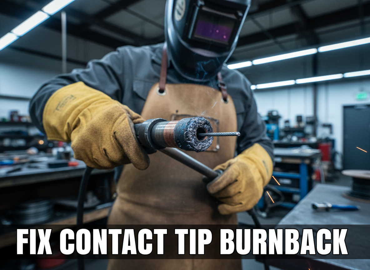
Your MIG gun stops feeding wire mid-weld. You power down, open the feeder, and find the wire welded solid into the contact tip. This is contact tip burnback—and it costs you time, consumables, and weld quality. The good news: it’s preventable with the right tip and maintenance routine.
Key Takeaways
The Problem
Contact tip burnback occurs when the wire gets stuck inside the contact tip and actually welds itself to the copper. This happens because:
The result: the wire literally welds itself to the tip, and your feeder can’t push it through.
Why It Matters
Burnback stops your weld mid-joint. You lose:
On a job site or in a production shop, one burnback can cascade into multiple restarts and rework.
The Fix
Contact tip burnback is a tip problem, not a feeder problem. Here’s what to do:
Prevention: Replace contact tips every 8–10 hours of welding, or sooner if you notice spatter buildup or inconsistent arc.
Why This Product Solves It
The Miller MDX Series MIG Contact Tip (.045″ or 1.2mm) is engineered for consistent wire flow and durability. Miller’s AccuLock design ensures:
Using the correct tip size for your wire diameter is non-negotiable. A .035″ tip on .045″ wire will jam; a .045″ tip on .035″ wire will spit spatter. Miller tips are sized precisely to match your wire.
Product Link:
$25.87 In Stock
Miller MDX Series MIG Contact Tip (.045" or 1.2mm), part no. T-M045 (10 per pack).
What to Check Before You Buy
Real-World Use
A fabrication shop running a Miller MDX-100 on .045″ mild steel was experiencing burnback every 30–40 minutes. The operator was using undersized .035″ tips (wrong size). After switching to Miller .045″ tips and cleaning the nozzle every 4 hours, burnback stopped entirely. Production time increased by 15%.
Common Mistakes
Safety Notes
Contact tips get hot during welding. Always allow the gun to cool before removing the nozzle or tip. Wear welding gloves when handling hot consumables. If you’re replacing tips while the welder is still warm, keep your hands clear of the arc area and power down the welder first.
Always follow the manufacturer’s instructions and your shop’s safety procedures. If you’re unsure about fitment or ratings, verify before you buy or install.
Related Reading
Where to Buy
Available at ArcWeld.store (stock and shipping: Unknown – verify)
$25.87 In Stock
Miller MDX Series MIG Contact Tip (.045" or 1.2mm), part no. T-M045 (10 per pack).
Your MIG wire is burning back and fusing to the contact tip, stopping your weld cold. This happens when the wire arcs at the tip instead of at the workpiece—a sign of poor contact, dirty metal, or feeding issues. Fix it in 10 minutes with the right diagnosis.
What You’ll See:
Most Likely Causes (Ranked by Frequency):
Step 1: Inspect the Contact Tip (Free)
Step 2: Check Your Base Metal (Free)
Step 3: Verify Wire Feed Tension (Free)
Step 4: Check Electrical Connections (Free)
Step 5: Inspect the Gun Cable and Liner (Free to $30)
Step 6: Replace the Contact Tip and Liner (if needed) ($20–$50)
If you’ve cleaned the tip and it still won’t work, or if you’re welding regularly, a multi-pack of contact tips ensures you always have a fresh tip on hand. Worn tips are the #1 cause of burnback; replacing them every 50–100 hours of welding prevents the problem before it starts.
Why It Works:
When to Use It:
When NOT to Use It:
What to Check Before Buying:
Last update on 2026-06-20 / Affiliate links / Images from Amazon Product Advertising API
If you prefer a smaller pack or different wire size:
Q: Can I clean a burnt contact tip and reuse it? A: Yes, if it’s just spatter. Use a contact tip cleaner or small wire brush. If the opening is enlarged or pitted, replace it—a worn tip won’t conduct properly.
Q: How often should I replace my contact tip? A: Every 50–100 hours of welding, or sooner if you see spatter buildup or burnback. Frequent welders replace tips monthly.
Q: Why does my wire burn back even after I cleaned the tip? A: Check your base metal (is it rusty?), wire feed tension (is it too tight?), and electrical connections (is the ground clamp clean?). Burnback is rarely just the tip.
Q: Can a kinked gun cable cause burnback? A: Yes. A bent cable restricts wire flow, starving the arc. Straighten the cable or replace it if it’s cracked.
Q: What’s the difference between burnback and wire sticking? A: Burnback is when the wire fuses to the tip (arc at the tip, not the workpiece). Wire sticking is when the wire jams in the tip but hasn’t melted. Both have similar causes: dirty tip, poor prep, or feeding issues.
For more welding fixes and gear options, see our full resource page: https://blog.weldsupportparts.com/links/
Plasma cuts that leave a thick “slag” ridge on the bottom edge are usually telling you the arc isn’t transferring cleanly. If you’re cutting plate and spending more time grinding than cutting, this is the fast checklist to get clean edges again. Here’s why it happens and how to fix it.
Symptoms (what you’ll see):
Root Cause (what’s actually happening):
Heavy bottom dross is typically caused by a mismatch between travel speed, torch standoff/drag technique, and air quality/pressure. When you move too slowly (or hold the torch too high/too low for the consumables you’re using), the arc lingers and the molten metal doesn’t blow out of the kerf cleanly—so it re-freezes as dross on the bottom edge.
Once you’ve run a set of consumables past their useful life, the nozzle orifice can erode and the electrode can pit. That degrades arc shape and airflow, which makes dross and bevel worse even if your technique is decent.
The Fix (step-by-step):
Real-World Tip:
Experienced plasma users don’t “fight” dross with more amps—they do quick test cuts and tune speed first, then height, then air. If the cut suddenly gets worse after it was fine yesterday, they assume air moisture or consumables before anything else.
Soft CTA (MANDATORY):
If this keeps happening, your plasma consumables (nozzle/tip + electrode + shield) are likely worn or damaged. See the best replacement options → [BUYER PAGE LINK PLACEHOLDER]
Safety Note:
Wear eye/face protection and gloves—plasma cutting throws hot sparks and slag. Use ANSI Z87.1-rated eye protection and keep flammables clear of the work area.
