The Millermatic 211 PRO is a portable dual-voltage MIG and flux-cored welder, but the machine is only part of the setup. Most day-to-day welding problems still come back to contact tips, nozzle spatter, liner drag, wire size mismatch, gas coverage, or poor work lead contact.
This guide is for buyers comparing the Millermatic 211 PRO and for owners who want the right consumable strategy before burnback, birdnesting, sputtering, or porosity starts wasting tips and wire.

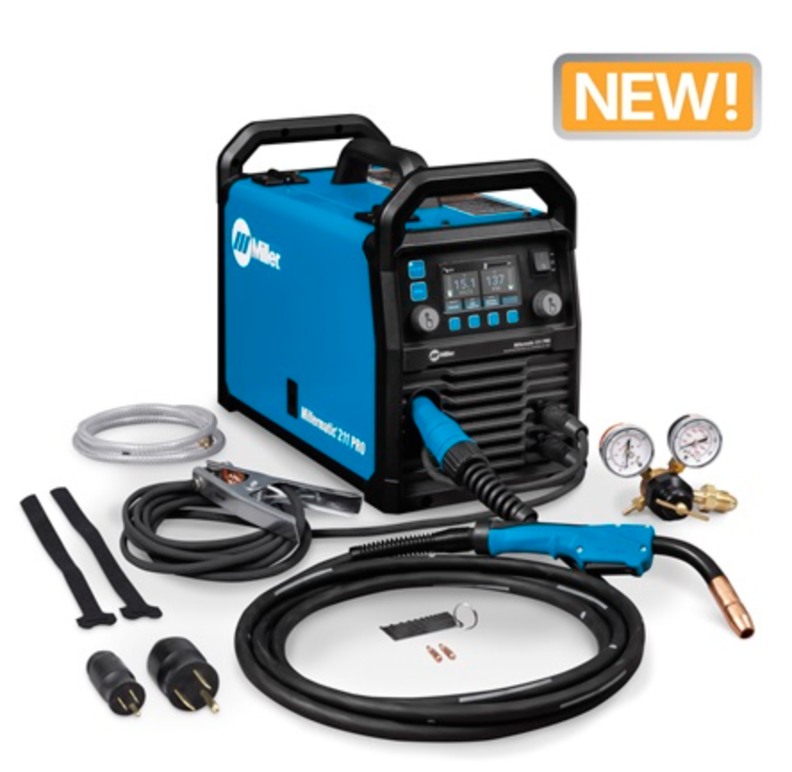
- Dyna-Pulse MIG Welding: Now with Dyna-Pulse MIG, this welder supports mild steel, stainless steel, aluminum (with spool gun), and flux-cored wire; powered by continually upgradable USB-enabled software
- BeadVision & Auto-Set: Built-in BeadVision delivers real-time bead monitoring for greater control; Auto-Set simplifies setup while Smooth-Start eliminates spatter for clean arc starts every time
- Program Memory & Weld Longer: Save and recall your most-used weld parameters with new Program Memory; weld longer with a higher duty cycle — ideal for a dependable, high-performance MIG welding machine
- Dual Voltage with MVP Plug: Easily switch between 120V and 240V with no tools needed; plug-and-play flexibility makes this a top choice for a portable MIG welder for shop or job site use
- Heavy-Duty Drive System & Spool Gun Ready: Angled cast-aluminum drive, Quick Select drive roll, .024–.035 in. wire support; auto-detects spool gun for seamless aluminum welding — 15-ft MIG gun included
Last update on 2026-07-14 / Affiliate links / Images from Amazon Product Advertising API
Key Takeaways
- The verified ASIN B0FFWV5DJG is associated with the Miller Millermatic 211 PRO MIG welder listing found in Amazon search results.
- Miller lists the Millermatic 211 PRO for 120 V or 240 V input, solid/stainless wire from .024–.035 in., flux-cored wire from .030–.035 in., and 60–600 IPM wire feed speed.
- The first wear items to stock are contact tips, nozzles, wire liner, drive rolls matched to wire type, anti-spatter, and PPE.
- Burnback is usually not a “bad welder” problem. Start with tip size, wire feed drag, nozzle spatter, stickout, and voltage/wire speed balance.
- For best shop readiness, keep spare contact tips in every wire size you run and verify MDX-100 consumable compatibility before ordering.
Problem / Context: Why a Good MIG Welder Still Needs a Consumables Plan
A new MIG welder can feel like an upgrade right away, but consumable neglect will make even a capable machine act inconsistent. The symptoms usually show up as wire burning back into the tip, wire stubbing into the puddle, erratic arc starts, excess spatter, or weld porosity.
The Millermatic 211 PRO gives you dual-voltage flexibility and enough wire-feed range for common shop work, but the gun still depends on correct fit-up: the contact tip must match the wire diameter, the liner must match the wire and gun length, the nozzle must stay clear, and the drive system must feed without crushing or slipping the wire.
Verified Product Snapshot
| Product | Miller Millermatic 211 PRO MIG Welder |
| Verified ASIN | B0FFWV5DJG |
| Process focus | MIG / GMAW and flux-cored welding |
| Input voltage | 120 V or 240 V, per Miller product data |
| Wire feed speed | 60–600 IPM, per Miller product data |
| Solid / stainless wire range | .024–.035 in., per Miller product data |
| Flux-cored wire range | .030–.035 in., per Miller product data |
| Included gun compatibility | MDX-100 MIG gun referenced in Miller literature; verify exact package contents and consumables before purchase |
Root Causes of Common Problems After Buying a Millermatic 211 PRO
1. Contact Tip Burnback
Burnback happens when the wire fuses to the contact tip. Common triggers include too little wire speed, too short stickout, wrong tip size, a worn tip bore, a clogged nozzle, poor work clamp contact, or wire drag inside the gun.
Related internal guide: Why Does My MIG Wire Burn Back and Stick to the Contact Tip?
2. Birdnesting at the Drive Rolls
Birdnesting usually points to feed resistance downstream of the drive rolls. Check the contact tip first, then the liner, gun cable bends, drive roll groove, wire spool tension, and drive tension. Do not simply crank down the drive rolls; crushed wire sheds debris and can make the liner problem worse.
3. Porosity from Poor Gas Coverage
Porosity can come from contamination, wind, low shielding gas, wrong gas, leaks, a clogged nozzle, or an excessive stickout. Before blaming the machine, clean the base metal, inspect nozzle spatter, verify gas flow, and make a test bead on clean scrap.
4. Sputtering and Inconsistent Arc
Sputtering often looks like a settings problem, but worn contact tips, incorrect wire size, dirty liner, poor ground, and feed tension issues are frequent causes. Check consumables before making large voltage or wire speed changes.
Related internal guide: MIG Settings Troubleshooting
What Wears Out First
| Wear Item | What Fails | Typical Symptom | Action |
|---|---|---|---|
| Contact tip | Bore wears, spatter sticks, wire fuses | Burnback, erratic arc, wire drag | Replace with correct wire diameter |
| Nozzle | Spatter restricts gas flow | Porosity, spatter, unstable arc | Clean or replace |
| Liner | Debris, kinks, wrong diameter | Surging feed, birdnesting, burnback | Replace with compatible liner |
| Drive rolls | Wrong groove or worn groove | Wire slipping or shaving | Match roll to wire type and size |
| Work clamp / cable connection | Loose or dirty contact | Hard starts, unstable arc | Clean and tighten |
| Shielding gas setup | Leaks, incorrect flow, empty cylinder | Porosity, oxidation, dirty bead | Leak-check and verify flow |
Visual Wear Indicators
- Oval contact tip hole: replace the tip.
- Wire welded into the tip: replace the tip and check feed drag.
- Heavy spatter inside nozzle: clean or replace the nozzle.
- Wire dust near drive rolls: reduce over-tension and inspect liner.
- Arc surges when gun cable is bent: suspect liner drag or a kinked gun lead.
- Porosity appears after several minutes of welding: check nozzle blockage, gas flow, and cylinder level.
Solution: Millermatic 211 PRO Setup Checklist Before the First Weld
- Confirm input voltage and plug setup for the job.
- Install wire that falls within the machine’s supported wire diameter range.
- Match the contact tip to the exact wire diameter.
- Match the drive roll groove to the wire type and size.
- Keep the gun cable as straight as practical while feeding wire.
- Set drive tension only tight enough to feed without slipping.
- Clean the base metal and attach the work clamp to clean metal.
- Verify shielding gas flow when using solid wire.
- Use flux-cored polarity only as specified by the wire and machine setup instructions.
- Run a test bead on scrap before welding the final part.
Product Recommendations
Best Overall Machine Pick: Millermatic 211 PRO MIG Welder
For a buyer who wants a higher-quality portable MIG platform instead of a bargain welder, the Millermatic 211 PRO is the central pick for this page. It makes the most sense for a shop that wants 120 V convenience, 240 V capability, solid wire, stainless wire, flux-cored wire, and a consumables ecosystem that can be maintained over time.
- Dyna-Pulse MIG Welding: Now with Dyna-Pulse MIG, this welder supports mild steel, stainless steel, aluminum (with spool gun), and flux-cored wire; powered by continually upgradable USB-enabled software
- BeadVision & Auto-Set: Built-in BeadVision delivers real-time bead monitoring for greater control; Auto-Set simplifies setup while Smooth-Start eliminates spatter for clean arc starts every time
- Program Memory & Weld Longer: Save and recall your most-used weld parameters with new Program Memory; weld longer with a higher duty cycle — ideal for a dependable, high-performance MIG welding machine
- Dual Voltage with MVP Plug: Easily switch between 120V and 240V with no tools needed; plug-and-play flexibility makes this a top choice for a portable MIG welder for shop or job site use
- Heavy-Duty Drive System & Spool Gun Ready: Angled cast-aluminum drive, Quick Select drive roll, .024–.035 in. wire support; auto-detects spool gun for seamless aluminum welding — 15-ft MIG gun included
Last update on 2026-07-14 / Affiliate links / Images from Amazon Product Advertising API
Budget Option: Consumables First
If the machine is already in your shop, the budget upgrade is not another welder. Start with correct-size contact tips, a clean nozzle, anti-spatter, fresh wire, and a liner inspection. Unknown ASINs: Verify before adding AAWP boxes.
Heavy-Duty Option: Spare Gun Consumables Kit
For repeated shop use, keep a dedicated MDX-100-compatible consumables kit with contact tips, nozzles, diffuser-related parts, and a spare liner. Compatibility must be verified against the exact gun and Miller part numbers before purchase.
Upgrade Path: Spool Gun for Aluminum
If aluminum MIG is part of the plan, verify the supported Miller spool gun for the Millermatic 211 PRO package. Aluminum wire is soft and feed-sensitive, so a spool gun can reduce feed problems compared with pushing soft wire through a long MIG gun liner. Exact spool gun compatibility: Unknown (Verify).
Related Accessory: Anti-Spatter and Nozzle Cleaning Tools
Anti-spatter and a nozzle cleaning tool are low-cost prevention items. They help keep gas flow open around the contact tip and reduce the chance that spatter buildup gets misdiagnosed as a machine settings problem.
Comparison Table: Machine vs. Consumables vs. Accessories
| Category | Best Use | Buyer Intent | AAWP Status |
|---|---|---|---|
| Millermatic 211 PRO | Primary MIG / flux-cored welding platform | Best overall machine upgrade | Verified ASIN: B0FFWV5DJG |
| Contact tips | Burnback, unstable arc, wire drag | Replacement consumable | Unknown ASIN (Verify) |
| Nozzles | Porosity and spatter control | Replacement consumable | Unknown ASIN (Verify) |
| Gun liner | Birdnesting, surging feed, wire drag | Troubleshooting replacement | Unknown ASIN (Verify) |
| Drive rolls | Wire slipping, shaving, flux-core setup | Compatibility part | Unknown ASIN (Verify) |
| Anti-spatter | Nozzle maintenance | Preventative item | Unknown ASIN (Verify) |
| Welding gloves / helmet | Arc, heat, sparks, grinding prep | PPE buying intent | Unknown ASIN (Verify) |
Recommended Spare Quantity
- Contact tips: keep 10 per wire size you use most often.
- Nozzles: keep 2–3 spares for the gun.
- Liner: keep 1 spare liner matched to wire size and gun length.
- Drive rolls: keep the correct roll set for solid wire and flux-cored wire if you run both.
- Wire: keep one sealed backup spool of your most common diameter.
- PPE: keep spare cover lenses, gloves, safety glasses, and ear protection near the welder.
Recommended Shop Setup
A practical Millermatic 211 PRO setup includes the welder, cart or stable surface, properly chained gas cylinder, clean work clamp area, dry wire storage, tip/nozzle organizer, anti-spatter, nozzle pliers, wire brush, flap discs, gloves, helmet, safety glasses, and ventilation appropriate for the material being welded.
Related internal guide: Flap Disc Prep and Weld Cleaning
Related internal guide: Welding Safety Equipment
Common Misdiagnosis
- “The welder is defective” when the contact tip is actually worn or the liner is dragging.
- “I need more drive roll tension” when the wire path is blocked downstream.
- “The gas is bad” when the nozzle is packed with spatter.
- “The voltage is wrong” when the work clamp is attached to dirty metal.
- “The wire is junk” when the wrong contact tip size is installed.
If Ignored
Ignoring consumable wear leads to wasted contact tips, wasted wire, poor starts, spatter cleanup, porosity repairs, and unnecessary troubleshooting time. In production or repair work, the hidden cost is often not the contact tip itself; it is the time spent stopping, clipping wire, clearing the gun, grinding defects, and restarting.
Related Failures
- MIG troubleshooting problems from worn consumables
- MIG consumables that cause burnback and unstable arc
- Wire burnback at the contact tip
- MIG settings symptoms that are really feed problems
- Poor prep that causes weld contamination
FAQ
Is B0FFWV5DJG the Millermatic 211 PRO?
Search results verified B0FFWV5DJG as an Amazon listing associated with the Miller Millermatic 211 PRO MIG welder. Always confirm the product title, seller, package contents, and warranty details on Amazon before publishing or purchasing.
What contact tips fit the Millermatic 211 PRO?
The Millermatic 211 PRO literature references MDX-100 MIG gun consumables, but exact tip part numbers and compatibility should be verified against the included gun, wire size, and current Miller documentation before ordering.
Why does my MIG wire burn back into the tip?
Burnback usually comes from poor wire feed, incorrect stickout, wrong contact tip size, too little wire speed for the voltage, a dirty nozzle, liner drag, or poor work lead contact. Replace the damaged tip first, then isolate feed resistance.
Should I buy extra consumables with the welder?
Yes. At minimum, keep contact tips for each wire size, spare nozzles, a liner, anti-spatter, and PPE consumables. A good welder without spare tips can still stop a job over a minor burnback event.
Can the Millermatic 211 PRO weld aluminum?
Miller and Amazon listing text reference aluminum capability with a spool gun. Verify the exact supported spool gun, package contents, calibration steps, and aluminum wire requirements before buying accessories.
Is a larger MIG welder better than replacing consumables?
Not when the symptom is burnback, birdnesting, porosity, or erratic arc caused by the gun setup. Replace worn consumables and verify wire feed first. Upgrade machine capacity only when the material thickness, duty cycle, or process needs exceed the welder’s limits.
Safety Notes
- Disconnect or power down the welder before removing the contact tip, nozzle, liner, or drive roll components.
- Wear welding helmet, gloves, flame-resistant clothing, and safety glasses during welding and grinding prep.
- Secure shielding gas cylinders upright so they cannot fall.
- Use ventilation suitable for the material, coating, filler wire, and work area.
- Do not weld on unknown coated, galvanized, painted, or contaminated metal without proper hazard controls.
- Follow the Miller owner’s manual and applicable AWS, OSHA, and ANSI safety guidance.
Sources Checked
- Miller Millermatic 211 PRO product page and specification data.
- Miller Millermatic 211 PRO owner’s manual.
- Miller Millermatic 211 PRO literature referencing MDX-100 MIG gun consumables.
- Amazon search result for ASIN B0FFWV5DJG.
- Weld Support Parts internal MIG troubleshooting, MIG consumables, flap disc, and welding safety pages.
- OSHA welding, cutting, and brazing safety guidance.
- ANSI Z49.1 welding safety guidance referenced for general safety context.

 Note for Readers: This post may contain affiliate links. If you purchase through them, we may earn a small commission at no cost to you. Thank you for supporting our site.