Tag: maintenance

  • Tweco 44-116-25, Replacement Liner/Conduit, Pack of (1): Product Breakdown

    Tweco 44-116-25, Replacement Liner/Conduit, Pack of (1): Product Breakdown

    Product not found.
    “>Tweco 44-116-25, Replacement Liner/Conduit, Pack of (1)

    If a MIG gun starts feeding erratically, the liner is one of the first wear parts to inspect. The Tweco 44-116-25, Replacement Liner/Conduit, Pack of (1) is listed as a 1/16″ x 25′ zinc plated MB spring wire liner intended for certain Tweco MIG gun families. For maintenance buyers and welding support teams, the key question is not just what the part is called, but whether it matches the gun, wire, and feed path you are servicing.

    This breakdown stays focused on practical use: what to verify before ordering, what to inspect during install, and how to troubleshoot feeding problems after replacement. Where technical details are not confirmed by the provided source, they are marked Unknown (Verify).

    Key Takeaways

    • The Tweco 44-116-25 is a replacement liner/conduit, not a complete gun assembly.
    • The supplied product description identifies it as a 1/16″ x 25′ zinc plated MB spring wire liner.
    • Listed gun families include 300 – 500 amp Tweco Eliminator, Tweco Spray Master, Tweco No. 3, Tweco No. 4, and Tweco No. 5 X-Gun MIG guns.
    • Final fit depends on gun model, cable length, wire diameter, and feed setup. Verify before purchase.
    • If the liner is the wrong type or length, feeding problems can persist even when the drive rolls are in good condition.

    What This Part Does

    A MIG gun liner guides wire from the feeder through the cable to the contact tip. In service, the liner must stay smooth internally and properly matched to the wire being run. A spring-style liner can support feeding in heavier-duty applications, but the correct selection still depends on the specific gun and application. The source listing identifies the liner as zinc plated MB spring wire liner, but any additional material details beyond that are Unknown (Verify).

    Check Before You Order

    Use these checks before replacing a liner:

    • Inspect the gun model. Confirm the MIG gun family on the handle, cable tag, or service record.
    • Verify cable length. The product is listed as 25′. Match this to the gun cable length in service.
    • Check wire diameter. The listing includes 1/16″ in the product description, but verify the actual wire size in your process.
    • Review the feed symptom. Birdnesting, inconsistent feed speed, and wire scrape marks can point to liner wear or mismatch.
    • Inspect the current liner. Look for scoring, rust, debris, kinks, or crushed sections.

    Verify: If the existing liner was changed to solve a problem once before, confirm whether the root cause was actually the liner or another part of the feed system. Drive rolls, inlet guides, gun neck angle, and cable routing can create similar symptoms.

    Troubleshooting Support

    When wire feed is unstable, go through the system in order.

    1) Feed from the feeder first

    • Inspect: Drive roll condition and tension.
    • Check: Inlet guide alignment into the gun connection.
    • Verify: The wire feeds smoothly before it enters the gun cable.

    2) Move to the cable

    • Inspect: Cable bends, crushed areas, and twist points.
    • Check: Whether the gun is being used in a tight routing position that increases drag.
    • Verify: The cable is not damaged externally before replacing the liner.

    3) Check the liner itself

    • Inspect: Liner ends for burrs or deformation.
    • Check: Internal wear by comparing feed feel before and after removal.
    • Verify: The liner path is clean and free of contamination from old wire dust or rust.

    4) Confirm the contact tip and neck components

    • Inspect: Tip wear and bore condition.
    • Check: Whether the tip matches the wire size in use.
    • Verify: Heat damage or spatter build-up is not causing the wire to bind.

    If feeding improves after the liner change but problems return quickly, do not assume the liner was the only issue. Verify wire quality, spool condition, and whether the process is pushing the gun beyond its normal duty conditions. Any exact compatibility outside the product listing remains Unknown (Verify).

    Installing a Replacement Liner: Practical Steps

    1. Power down the machine and isolate the welding circuit.
    2. Remove the consumables and release wire tension.
    3. Withdraw the old liner carefully to avoid leaving fragments in the cable.
    4. Inspect the cable path for debris, wear, or internal obstruction.
    5. Insert the new liner slowly and keep it from kinking.
    6. Trim only as required by the gun setup after confirming length and seating.
    7. Reassemble the gun and reinstall consumables.
    8. Test feed at low speed first, then verify under normal operating settings.

    Verify: The source listing does not provide installation tolerances, trim allowances, or torque values. Those details are Unknown (Verify) and should be taken from the gun manufacturer’s service documentation.

    When to Replace Instead of Clean

    Cleaning can help when the liner is only contaminated. Replacement is usually the better choice when the liner is scored, rusted, crushed, or repeatedly causing drag after the rest of the feed path has been checked. If a gun is used in a high-production environment, a liner may become a scheduled wear item rather than an emergency repair part.

    Product and Parts Notes

    The provided ArcWeld product listing identifies this item as the Tweco 44-116-25, Replacement Liner/Conduit, Pack of (1). The short description states it is a 1/16″ x 25′ zinc plated MB spring wire liner for use with 300 – 500 amp Tweco Eliminator, Tweco Spray Master, Tweco No. 3, Tweco No. 4, and Tweco No. 5 X-Gun MIG guns. No additional compatibility should be assumed beyond that listing. If your gun variant differs from the named families, verify before ordering.

    Product reference:

    Tweco 44-116-25, Replacement Liner/Conduit, Pack of (1)

    Tweco 44-116-25, Replacement Liner/Conduit, Pack of (1)

    Tweco Model 44-116-25 1/16" X 25' Zinc Plated MB Spring Wire Liner For Use With 300 – 500 Amp Tweco® Eliminator®, Tweco® Spray Master®, Tweco® No. 3, Tweco® No. 4, Tweco® No. 5 X-Gun MIG Guns

    View at Arc Weld Store

    For related feed-wire context, see this internal article: Aluminum ER 5554 3/64″ X 5lb. MIG Welding Wire Spool By Washington Alloy – Weld Support Parts Blog. That page is not a liner guide, but it can help support teams think through wire handling and feed consistency when reviewing the whole system.

    Safety Notes

    • De-energize equipment before service.
    • Keep hands clear of sharp wire ends during liner removal and trim.
    • Do not force a liner into a cable if it binds; inspect the cable and gun path first.
    • Use the correct personal protective equipment for shop service work.
    • Follow the gun and power source manufacturer’s service instructions where available.

    FAQ

    Is the Tweco 44-116-25 a complete gun?

    No. It is a replacement liner/conduit only, based on the provided product listing.

    Can I use this liner on any Tweco gun?

    No. The listing names specific Tweco gun families, but final fit still needs to be verified against your exact model and cable setup. Unknown (Verify) for any unlisted variants.

    What usually causes feeding issues if the liner is new?

    Drive roll tension, damaged cable routing, incorrect tip size, dirty wire, or a mismatched liner can still cause feed problems. Verify the full feed path, not just the liner.

    Should I clean the old liner or replace it?

    Clean only if contamination is the likely issue and the liner is still in serviceable condition. Replace it if there is scoring, rust, deformation, or recurring drag.

    Sources Checked

    • ArcWeld product listing: Tweco 44-116-25, Replacement Liner/Conduit, Pack of (1)
    • Provided internal product description and source URL for the same item
    • Allowed internal link: Weld Support Parts blog article on aluminum MIG wire handling

    Related Weld Support Guides

  • Hypertherm 220990, 105 Amp Nozzles for Powermax 105, Pack of (5): Replacement Part Breakdown

    Hypertherm 220990 is a consumable replacement nozzle pack listed for Powermax 105 use. For buyers and maintenance teams, the main job is not just ordering the part; it is confirming that the nozzle match is correct for the torch, amperage setting, and current wear condition. Consumables fail in ways that affect cut quality fast, so replacement decisions should be based on inspection, not guesswork.

    This guide breaks down what to check before you buy, how to inspect the nozzle stack after shutdown, and how to troubleshoot the symptoms that usually point to nozzle wear or mismatch. Product details beyond the listing itself are marked Unknown (Verify) when not confirmed.

    Key Takeaways

    • Hypertherm 220990 is listed as a 105 amp nozzle pack for Powermax 105 use.
    • Consumable replacement should follow visual inspection and cut-quality symptoms, not only runtime.
    • Check the full torch consumable stack, not just the nozzle, before ordering parts.
    • If fitment, torch family, or amperage is not confirmed, use Unknown (Verify) until verified by the equipment manual or parts list.
    • Use the Amazon product box below as a buying reference only; do not assume compatibility beyond the listing title.

    What this part is for

    The listing identifies this item as a nozzle replacement pack for a Hypertherm Powermax 105 system. In plasma cutting, the nozzle controls the constricted arc as it exits the torch. When the nozzle wears, the arc can lose focus and the cut can become wider, rougher, or less stable. That is why nozzle replacement is part of routine torch maintenance.

    Do not assume this nozzle is interchangeable with other amperage ratings or other Powermax models unless you verify the torch manual, the OEM parts list, or the markings on the existing consumables. If the exact torch or cartridge arrangement is not confirmed, mark it Unknown (Verify).

    Check before you order

    1. Inspect the torch model. Verify the machine and torch are actually Powermax 105 compatible.
    2. Check the nozzle rating. Confirm the current nozzle is a 105 amp nozzle, not a different amp class.
    3. Inspect the consumable stack. Look at the nozzle, electrode, swirl ring, shield, retaining cap, and any retaining hardware.
    4. Verify the wear pattern. Excessive pit formation, ovality, meltback, or arc instability suggests replacement is due.
    5. Confirm count and pack size. The product title shows a pack of five; verify that is what you need for stock or service planning.

    Troubleshooting: when to suspect nozzle wear

    If cut quality changes, the nozzle may be the cause, but it is not the only cause. Use a simple inspection sequence.

    Check

    • Check for a wider-than-normal kerf.
    • Check for heavy dross that appears suddenly after a period of normal cutting.
    • Check for an unstable arc or frequent arc transfer problems.
    • Check for visible heat damage on the nozzle or adjacent consumables.

    Inspect

    • Inspect the nozzle orifice for distortion, enlargement, or meltback.
    • Inspect the electrode for wear; a new nozzle with a worn electrode can still cut poorly.
    • Inspect the shield and swirl ring for contamination, cracking, or heat damage.
    • Inspect the torch body and retaining parts for debris, looseness, or damaged threads.

    Verify

    • Verify the amperage setting matches the consumable rating.
    • Verify the air supply is clean and dry.
    • Verify the torch assembly is seated correctly.
    • Verify the part number against the OEM parts list before stocking replacements.

    If the cut problem remains after replacing the nozzle, the issue may be elsewhere in the stack or in system setup. In that case, the nozzle is not the sole corrective action.

    Replacement support notes for maintenance buyers

    For shops that keep consumables on hand, part control matters. Separate nozzles by torch model and amperage class. Do not mix open stock between similar-looking plasma parts. A correct-looking nozzle with the wrong internal geometry can create false confidence and waste labor time.

    When you receive replacement parts, compare them against the old part before installation. Match the outside dimensions, contact surfaces, and visible openings as far as the OEM design allows. If any feature is unclear, treat it as Unknown (Verify) and stop before installation.

    Product / parts reference

    Hypertherm 220990, 105 Amp Nozzles for Powermax 105, Pack of (5)

    Amazon product reference:

    No products found.

    Use this as the identified replacement listing only. Do not infer additional specifications, certifications, or machine compatibility beyond the product title unless you verify them from the OEM documentation.

    Safety notes

    • De-energize the plasma system before any consumable inspection or replacement.
    • Allow the torch and consumables to cool before handling.
    • Use eye protection and gloves when inspecting used plasma consumables.
    • Do not install damaged parts just to finish a job; damaged consumables can worsen cut quality and increase torch wear.
    • Keep compressed air and debris away from the work area during maintenance.

    FAQ

    Is this nozzle pack confirmed for every Powermax 105 torch?

    No. The listing title says it is for Powermax 105 use, but exact torch and configuration compatibility should still be verified against the OEM parts list. If unconfirmed, mark it Unknown (Verify).

    Can I replace only the nozzle if cut quality drops?

    Sometimes, but not always. Inspect the electrode, swirl ring, shield, and retaining parts as a set. A fresh nozzle will not fix damage or contamination in the rest of the consumable stack.

    What is the fastest way to tell if the nozzle is worn out?

    Look for visible orifice distortion, heat damage, or a cut that suddenly becomes wider and less stable. Then verify the amperage setting and air quality before ordering parts.

    Should I stock this part without testing the torch first?

    Only if your equipment records already confirm the torch model and consumable class. If not, verify the machine and torch details before putting the part into stock.

    Sources Checked

    • Provided Amazon product reference for ASIN B00KCPSYGA via allowed product shortcode
    • Internal project brief and topic metadata

    Note: No WSP lookup page or filler metal finder page was provided for this task, so no such internal links were added.

    Matched Replacement Option

    No products found.

    Disclosure: As an Amazon Associate, Weld Support Parts may earn from qualifying purchases.
    Related Weld Support Guides

  • Hobart Handler 140EZ MIG Welder Support: Parts Lookup and Buying Checks

    Hobart Handler 140EZ MIG Welder Support: Parts Lookup and Buying Checks

    Hobart Handler 140EZ MIG Welder Support

    The Hobart Handler 140EZ is a compact MIG setup, but support work still comes down to the same basics: confirm the machine variant, identify the gun and feeder parts you actually have, and verify consumable fit before placing an order. This guide is built for buyers, maintenance techs, and welders who need to replace worn items without guessing.

    Key Takeaways

    • Start with the machine support page before you buy parts or consumables.
    • Verify gun type, drive roll style, wire size, and contact tip fit before ordering.
    • Do not assume the package contents match a unit that has been modified in service.
    • Use filler metal pages as a selection starting point, not as a guarantee of procedure approval.
    • If a compatibility point is not confirmed on the support page, mark it as Unknown (Verify).

    What to Check on a Hobart Handler 140EZ Before Ordering Parts

    Before you order anything, inspect the machine as it sits in the shop. A unit that has been in service may have a different gun, cable length, liner, drive roll, or wire path than the original package. That affects what will fit.

    Check

    • Confirm the exact machine model on the nameplate.
    • Inspect the gun and cable for wear, cuts, heat damage, or a loose neck connection.
    • Look at the drive rolls and note the wire size marking if present.
    • Verify the installed contact tip size and thread style before buying replacements.
    • Check the wire spool size and wire type currently in use.

    Inspect

    • Feed path: look for dust, liner wear, or birdnesting signs.
    • Contact tip: check for arc instability, oval wear, or spatter buildup.
    • Nozzle: inspect for spatter closure, heat distortion, or missing insulator parts.
    • Drive system: verify whether the roll surface matches the wire you run.

    Verify

    • Confirm whether the installed gun is the HM-100 MIG gun referenced on the support page.
    • Verify whether the unit uses a SpoolRunner 150 arrangement or a standard feeder setup, if applicable to your machine. Unknown (Verify) if not confirmed by the support page or machine inspection.
    • Verify the wire diameter you intend to run before ordering tips, liners, or rolls.

    WSP Lookup: Hobart Handler 140EZ Support Page

    The primary starting point for this model is the Weld Support Parts support page here: Hobart Handler 140EZ MIG Welder Support.

    Use that page to review the model-specific support notes, listed package contents, and the consumable and accessory references tied to the Hobart Handler 140EZ. The page also references the HM-100 MIG gun, the SpoolRunner 150, drive rolls, and consumable part links. If a part or configuration is not explicitly confirmed there, treat it as Unknown (Verify).

    Practical buying check: compare the support page against your machine in the shop. If the machine has been repaired, upgraded, or altered, do not rely on memory or a prior invoice. Check the machine first, then match the part family.

    Troubleshooting Support: Common Ordering Mistakes to Avoid

    Most support problems happen before the order is placed. The wrong consumable or gun component may still look close enough to fit, but a close visual match is not enough.

    Check for these issues

    • Wrong wire diameter selected for tips and drive rolls.
    • Wrong gun family selected after a previous service swap.
    • Mixed consumable parts from different setups.
    • Assuming package contents are still original after ownership changes.
    • Replacing the liner or tip without checking the feeder condition.

    Inspect, then verify

    • Inspect the tip seat: confirm whether the existing tip threads or seats match the replacement part you plan to order.
    • Inspect the roll grooves: look for wear or polishing that suggests the roll has been used with a different wire size.
    • Verify the liner length and routing: if the gun cable has been replaced or shortened, liner fit may not match the original configuration. Unknown (Verify) if not documented.
    • Verify the consumable family: use the support page references, not guesswork from a similar Hobart machine.

    Drive Rolls, Tips, and Gun Parts: What to Match

    For a MIG feeder, the most common replacement items are drive rolls, contact tips, nozzles, liners, and the gun itself. Matching starts with the wire and ends with the feeder hardware.

    • Drive rolls: match roll type to wire type and wire size as confirmed on the machine.
    • Contact tips: match the tip to wire diameter and the correct gun family.
    • Nozzles and insulators: match the gun assembly shown on the support page or on the installed gun.
    • Liners: verify liner style and length before purchase. Unknown (Verify) if the machine has been modified.
    • Gun assembly: confirm whether you need the HM-100 MIG gun or another setup before ordering.

    Filler Metal Finder: Use It as a Starting Point

    If you are also selecting wire, use the Weld Support Parts filler metal content and wire selection resources as a starting point, not as a final approval document. A useful reference is this internal guide: Best MIG Wire for Stainless Steel (ER308L vs ER309L).

    That page helps frame selection decisions, but it does not replace procedure approval, WPS requirements, or base-metal review. For any production job, verify the required wire classification, shielding gas, and procedure requirements against your shop documentation. Unknown (Verify) if not documented.

    Buying Checks for Maintenance and Purchasing

    • Match the support page to the machine serial/model label.
    • Confirm whether the current gun and feeder parts are original or field-replaced.
    • Order by verified wire size and gun family, not by appearance.
    • Keep a record of the installed consumable part numbers after replacement.
    • When in doubt, stop and verify before opening the package for install.

    Safety Notes

    • Disconnect input power before inspection or part replacement.
    • Let the gun and nozzle cool before handling after welding.
    • Wear eye protection when checking the wire path, drive rolls, or contact tip area.
    • Do not run damaged gun cables, cracked nozzles, or worn liners in service.
    • Use the correct PPE and follow your shop lockout practices.

    FAQ

    How do I know which parts fit the Hobart Handler 140EZ?

    Start with the dedicated WSP support page for the model, then inspect the machine in the shop. Match the gun, consumables, and drive components to what is installed. If the part family is not confirmed, treat it as Unknown (Verify).

    Can I buy consumables based only on the model name?

    No. The model name is a starting point, not enough by itself. Confirm wire size, gun type, and the actual feeder setup before ordering tips, rolls, or liners.

    Is the SpoolRunner 150 definitely part of every Hobart Handler 140EZ package?

    No. The support page references the SpoolRunner 150, but package contents can vary by listing, revision, or prior modification. Verify the installed configuration before purchase.

    Can I use filler metal pages to approve a production weld procedure?

    No. Use filler metal pages to narrow down likely wire options only. Final approval must come from your WPS, procedure documents, or engineering requirements.

    Sources Checked

    All uncertain technical details should be verified against the machine in service and the referenced support page before ordering.

    Disclosure: As an Amazon Associate, Weld Support Parts may earn from qualifying purchases.

    Related Weld Support Guides

  • Metabo W11-125 Quick 9.6-Amp 5-Inch Angle Grinder: Replacement Part Breakdown

    The Metabo W11-125 Quick 9.6-Amp 5-Inch Angle Grinder is a common shop tool, but any grinder that sees regular cutting, grinding, and cleanup work will eventually need service. Bearings wear, brushes shorten, switches fail, cords get damaged, and guards or flanges get misplaced. For maintenance buyers and shop support teams, the useful question is not just what the grinder is called, but what can be checked, what can be replaced, and what must be verified before returning it to service.

    This guide is a practical replacement part breakdown for the Metabo W11-125 Quick B001CS9U5A. It does not assume a specific parts diagram or service kit unless verified by the manufacturer or seller documentation. Where technical details are not confirmed, they are listed as Unknown (Verify).

    Key Takeaways

    • Start with inspection, not part ordering. Many grinder failures look electrical but begin with mechanical wear.
    • Verify the exact model and serial information before ordering replacement parts.
    • Do not assume cross-compatibility with other 5-inch grinders.
    • Use original documentation or a verified parts breakdown when possible.
    • When a part detail is unclear, mark it Unknown (Verify) instead of guessing.

    What to Check First

    Before removing covers or ordering parts, confirm the symptom. This saves time and reduces the chance of replacing the wrong component.

    Check

    • Does the grinder start intermittently, not at all, or only under load?
    • Is there unusual vibration, noise, sparking, or heat?
    • Does the spindle turn freely by hand with the tool unplugged?
    • Are the guard, flange, wheel, and spindle lock operating correctly?

    Inspect

    • Power cord: cuts, crushed sections, exposed conductors, loose strain relief.
    • Switch: stiffness, arcing smell, intermittent contact.
    • Brushes and brush caps: wear length, spring pressure, carbon dust buildup. Exact brush dimensions: Unknown (Verify).
    • Bearings and gears: rough rotation, noise, side play, grease leakage.
    • Spindle and flange threads: damage, galling, or contamination.

    Verify

    • Tool model designation matches the service part source.
    • Voltage, amperage, and electrical configuration are verified from the nameplate or documentation before any electrical repair.
    • Any replacement guard, switch, brushes, bearings, or cord set is confirmed for this exact model or confirmed by the manufacturer as compatible.

    Replacement Part Breakdown: Typical Service Areas

    A grinder of this class usually has several serviceable areas. The exact part list for the Metabo W11-125 Quick should be taken from a verified parts diagram or service manual. The categories below are the parts most often inspected during maintenance.

    1. Power cord and strain relief

    The cord is one of the first wear points. Repeated bending near the entry point can break conductors inside the jacket before damage is visible outside.

    • Check for soft spots, cuts, flattened sections, or warm spots after brief operation.
    • Inspect the strain relief where the cord enters the housing.
    • Verify continuity and conductor integrity before reuse.

    2. On/off switch

    A failed switch often shows up as intermittent operation, delayed start, or no start. Dust and heat can shorten switch life in abrasive work.

    • Check for positive actuation and full return.
    • Inspect for discoloration, melted plastic, or loose terminals.
    • Verify switch replacement by exact model reference, not only by physical appearance.

    3. Carbon brushes

    Brush wear is routine on brushed motors. Short brushes can cause loss of power, excessive sparking, or stop-start behavior.

    • Inspect brush length and spring pressure.
    • Check the commutator area for heavy scoring or carbon dust.
    • Verify brush part number and dimensions from the correct parts source. Brush size for this model: Unknown (Verify).

    4. Bearings

    Worn bearings usually present as noise, rough rotation, or shaft play. If a bearing failure is ignored, the motor and gear train can be damaged further.

    • Rotate the shaft by hand with the tool unplugged.
    • Listen for grinding, rumbling, or scraping.
    • Verify bearing numbers from the service diagram or after teardown. Bearing numbers: Unknown (Verify).

    5. Gear set and spindle assembly

    Grinding work loads the gear train heavily. Impact loading, wheel pinch, and poor lubrication can damage gears or the spindle.

    • Inspect for chipped teeth, abnormal backlash, or metal debris in the housing.
    • Check spindle lock engagement and release.
    • Verify whether the spindle, flange, and lock components are sold separately or only as assemblies through the verified parts source.

    6. Guard, flange, and wheel hardware

    These are not wear items in the same way as brushes or bearings, but they are critical to safe operation.

    • Inspect the guard for cracks, deformation, and secure clamping.
    • Check backing flange and locking nut for damage or thread wear.
    • Verify wheel size and speed rating from the wheel label before installation. Wheel compatibility for this tool: Unknown (Verify) unless confirmed by the manufacturer documentation.

    Troubleshooting Support Flow

    Use this sequence when the grinder is out of service.

    1. Unplug the tool. Confirm zero power before any inspection.
    2. Check the cord and plug first. Many no-start complaints come from cord damage rather than internal failure.
    3. Inspect the switch. If the cord checks out, move to the switch and terminal connections.
    4. Spin the shaft by hand. Rough rotation points toward bearings or gear damage.
    5. Inspect brushes. If the motor runs but performs poorly, brush wear is a common cause.
    6. Verify the parts source. Do not order based on photos alone.

    If the problem is heat, smell, or sparking, stop use and inspect before applying power again. If the problem is mechanical binding, do not force the spindle lock or wheel hardware.

    How to Order the Right Replacement Part

    For a buyer guide, the most important control is identification. Do not rely on a generic “fits 5-inch grinder” claim.

    • Check the nameplate and record the exact model designation.
    • Use the verified parts breakdown or manufacturer service information if available.
    • Match the electrical and mechanical details before purchase.
    • If a part number cannot be confirmed, hold the order and verify with the seller or manufacturer.

    Product reference for this article:

    No products found.

    Safety Notes

    • Disconnect power before inspection, service, or part removal.
    • Do not defeat the guard, spindle lock, or switch mechanisms.
    • Use only wheels and accessories rated for the operating speed and application.
    • After replacement, perform a no-load test in a controlled area before returning the tool to production use.
    • If there is evidence of insulation damage, burned wiring, or internal arcing, remove the tool from service until repaired by a qualified technician.

    FAQ

    What parts wear out first on a grinder like this?

    Common wear items are the cord, switch, carbon brushes, bearings, and spindle hardware. Actual wear depends on duty cycle and the type of abrasive work.

    Can I order parts by appearance only?

    No. Appearance is not enough for safe ordering. Verify the exact model, part number, and source documentation before purchase.

    Is every 5-inch grinder part interchangeable?

    No. Size alone does not confirm compatibility. Switches, brushes, bearings, guards, and spindle parts may differ even between similar tools.

    What should I do if the tool runs but sounds rough?

    Unplug it and inspect the bearings, gears, wheel hardware, and spindle for wear or debris. Do not continue running a grinder that sounds rough under no-load conditions.

    Sources Checked

    • Provided Amazon product reference for Metabo W11-125 Quick B001CS9U5A
    • Task instructions and allowed-source constraints

    Note: No WSP lookup page, filler metal finder page, internal links, or additional verified product links were provided for this draft. No compatibility claims were made beyond what could be verified from the supplied source data.

    Disclosure: As an Amazon Associate, Weld Support Parts may earn from qualifying purchases.
  • Lincoln Viking 1740 Auto-Darkening Welding Helmet – K3282-3: Product Breakdown

    Lincoln Viking 1740 Auto-Darkening Welding Helmet – K3282-3: Product Breakdown

    Product not found.
    “>Lincoln Viking 1740 Auto-Darkening Welding Helmet - K3282-3

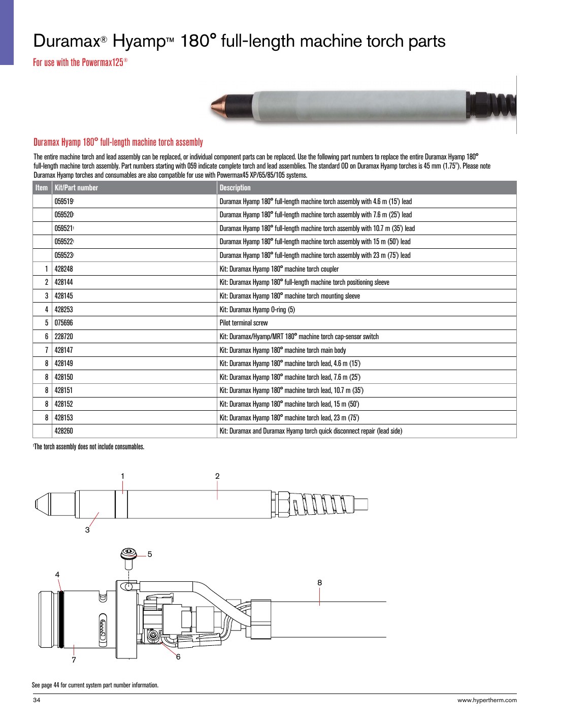
    The Lincoln Viking 1740 Auto-Darkening Welding Helmet – K3282-3 is a welding PPE item intended for day-to-day fabrication and repair work where a stable view of the weld zone matters. For buyers and support teams, the main question is not whether the helmet is “advanced,” but whether it fits the job, the user, and the maintenance routine. On a shop floor, consistent lens response, proper fit, and basic inspection discipline matter more than marketing terms.

    Key Takeaways

    • Auto-darkening helmets are support items for visibility and eye protection, not a substitute for correct process setup.
    • Inspect the shell, lens area, headgear, and sensors before each shift.
    • Verify that the user can see the joint clearly in the bright state and that the helmet stays positioned during work.
    • Replace damaged components early. Small issues in lens cover condition or headgear fit can become reliability problems.
    • If a detail is not confirmed in the source material, treat it as Unknown (Verify).

    What this helmet is for

    Based on the product description provided, this helmet is aimed at general fabrication and repair, shop work, field welding, and common arc processes such as MIG, TIG, and stick. The practical value of an auto-darkening helmet is simple: it lets the welder see the work area clearly before the arc starts, then darkens when the arc is struck. That reduces the need to repeatedly nod the hood up and down and can help reduce eye strain during repetitive work.

    For maintenance buyers, the priority is not just the helmet model name. It is whether the unit supports the welders’ actual tasks, how often consumable parts are checked, and whether the team has a repeatable inspection routine. If the application includes grinding, overhead welds, tight access work, or frequent start-stop cycles, the helmet must stay comfortable and reliable enough to avoid operator workarounds.

    Product / parts notes

    This article is limited to the product listing provided. Specific technical specs, lens sizes, shade ranges, sensor counts, and certification details were not supplied here, so they are Unknown (Verify). Do not assume compatibility with aftermarket headgear, cover lenses, or cartridge-style replacements unless the manufacturer documentation confirms it.

    For shop support, verify the following before issue or deployment:

    • Shell condition: inspect for heat damage, cracks, warping, and spatter buildup.
    • Lens area: check the outer and inner cover surfaces for pitting, clouding, scratches, and contamination.
    • Auto-darkening function: confirm the lens transitions properly during arc exposure in a controlled test.
    • Headgear: verify adjustment range, locking action, and that the helmet stays in position during head movement.
    • Seal and fit: confirm proper coverage around the face and neck area when used with other PPE.

    Troubleshooting and support checks

    1) Lens does not darken consistently

    • Check: confirm the helmet has power, if applicable. Power source details are Unknown (Verify) from the provided source.
    • Inspect: the sensors, cover lenses, and front face for dirt, spatter, or obstruction.
    • Verify: the arc is within normal working position and the helmet is aimed correctly at the weld zone.
    • Action: clean the lens surfaces and retest. If response remains inconsistent, remove the helmet from service until the fault is confirmed.

    2) Helmet feels loose or shifts during work

    • Check: the headgear adjustment points and tension settings.
    • Inspect: worn straps, cracked pivots, or damaged lock points.
    • Verify: the operator can tilt, lower, and raise the hood without it drifting out of position.
    • Action: replace worn support parts before the next shift. A loose helmet is a job-quality and safety problem.

    3) Visibility is poor even when the hood is up

    • Check: outer and inner covers for haze, slag impact, smoke film, or grinding dust.
    • Inspect: whether the lens is damaged or blocked by residue.
    • Verify: the user is not using the helmet in a way that exceeds its intended visibility setup.
    • Action: replace scratched cover lenses and clean the shell regularly. If the internal lens is degraded, escalate for replacement or service review.

    How to inspect before use

    1. Visual check: look over the shell for cracks, heat damage, and spatter.
    2. Lens check: inspect both cover surfaces for scratches, haze, or debris.
    3. Fit check: put the helmet on and verify secure headgear contact without pressure points that force the user to loosen the hood.
    4. Function check: perform a controlled arc-response test if shop procedure allows it.
    5. Record check: note any recurring issue, especially if the same helmet is being reassigned between shifts.

    Related support references

    If you are comparing this model to adjacent Lincoln helmet support content, these internal pages may help with broader helmet selection and setup context:

    Safety notes

    • Do not use a damaged helmet in production.
    • Do not rely on a visual appearance alone to confirm auto-darkening performance.
    • Inspect the helmet before every shift and after any impact, drop, or spatter event.
    • Confirm the helmet is used with the correct companion PPE for the task, including gloves, jacket, and respiratory protection when required.
    • If lens response, fit, or shell condition is uncertain, remove the unit from service until verified.

    FAQ

    Is the Lincoln Viking 1740 K3282-3 suitable for MIG, TIG, and stick welding?

    The provided product description says it is intended for daily MIG, TIG, and stick work. Specific duty limits, settings, and procedure approvals are Unknown (Verify).

    Can I use this helmet as a direct replacement for other Lincoln Viking models?

    Not without verification. Compatibility with other models, covers, headgear parts, or accessories is Unknown (Verify) unless the manufacturer documentation confirms it.

    What should I inspect first if the helmet starts acting up?

    Start with the basics: lens cleanliness, cover condition, sensor obstruction, headgear fit, and shell damage. In many cases, the issue is a contaminated cover lens or a loosened adjustment point.

    How often should the helmet be checked?

    At minimum, check it before each use. For shared helmets or high-volume shops, add shift-start and post-incident checks after drops, spatter strikes, or heavy grinding exposure.

    Sources Checked

    • ArcWeld product listing: Lincoln Viking 1740 Auto-Darkening Welding Helmet – K3282-3
    • Internal Weld Support Parts articles linked above

    For procurement or support decisions, keep the focus on fit, function, and inspection discipline. If a technical detail is not documented in the available source material, treat it as Unknown (Verify) before buying or issuing the helmet to the floor.

    Related Arc Weld Part

    Lincoln Viking 1740 Auto-Darkening Welding Helmet - K3282-3

    Lincoln Viking 1740 Auto-Darkening Welding Helmet – K3282-3

    Lincoln Viking 1740 Auto-Darkening Welding Helmet (K3282-3) is a professional-grade auto-darkening hood built for daily MIG, TIG, and stick work where clear visibility and consistent shade response matter. It’s designed to reduce eye strain by giving you a bright, high-clarity view of the puddle and joint before and during the arc. What it’s for General fabrication and repair Shop and field welding Processes with…

    View at Arc Weld Store

    Related Weld Support Guides

  • Markal 96823, Valve Action Black Paint Marker, Pack of (1): Product Breakdown

    Markal 96823, Valve Action Black Paint Marker, Pack of (1): Product Breakdown

    Product not found.
    “>Markal 96823, Valve Action Black Paint Marker, Pack of (1)

    The Markal 96823, Valve Action Black Paint Marker, Pack of (1) is a shop marking tool for layout, identification, and field marking where a standard ink marker is not enough. The product information provided identifies it as a real paint marker with valve action, a replaceable fiber nib, and a stated dry time of about 3 minutes. For welders, fabricators, and maintenance teams, the main value is simple: a marker that lays down visible paint on work surfaces and is built for repeated use.

    Key Takeaways

    Where this marker fits in a welding and fabrication shop

    A black paint marker is generally used for part identification, cut lines, fit-up notes, and general shop marking on surfaces where visibility matters. The valve-action design helps control paint flow, which is useful when marking long runs or repeated notes. If you need a mark that stays visible through handling, the real-paint format is usually more practical than a standard felt-tip marker.

    This is not a process-control device. It does not approve materials, procedures, or weld parameters. Use it as a shop marking tool only.

    Check, inspect, verify before use

    Troubleshooting and support

    If the marker does not perform as expected, use a simple inspection sequence before replacing it.

    Handling and use notes

    The listed features suggest a marker designed for straightforward manual use in the shop or field. Because it is a paint marker, treat it as a consumable that can dry out if left uncapped or handled incorrectly. Keep the cap secured when not in use. If the nib becomes worn, the replaceable tip supports continued use without discarding the entire body immediately.

    Use the marker for identification and layout only. Do not assume the mark remains permanent under grinding, blasting, heat, solvent exposure, or weather. Unknown (Verify) on resistance to these conditions because no additional performance data was provided.

    Product and parts notes

    Provided product information for the Markal 96823 identifies these details:

    Any use beyond those statements should be treated as Unknown (Verify). Do not assume surface chemistry, temperature limits, or chemical resistance without a current manufacturer data sheet or direct product confirmation.

    Safety notes

    FAQ

    Is the Markal 96823 a standard ink marker?
    No. The provided product information identifies it as a real paint marker with valve action.

    Can it be used on any metal surface?
    Unknown (Verify). Surface condition matters, and no full compatibility list was provided. Test on scrap or a non-critical area first.

    Does the marker dry fast enough for shop use?
    The stated dry time is 3 minutes. Actual dry time can change based on surface, film thickness, and environment, so verify on the part being marked.

    Can the nib be replaced?
    Yes. The provided information states that the fiber nib is replaceable.

    Sources Checked

    Related Arc Weld Part

    Markal 96823, Valve Action Black Paint Marker, Pack of (1)

    Markal 96823, Valve Action Black Paint Marker, Pack of (1)

    434-96823 Features: -Marks with real paint, dries in 3 minutes. -Nib releases paint as needed for continuous marking. -Lead-free, low halogens. -The fiber nib is replaceable to assure complete use of each marker. Product Type: -Markers. Category: -Paint. Dimensions: Overall Product Weight: -0.1 Pounds.

    View at Arc Weld Store
  • Hobart AirForce 12ci Plasma Cutter Support: Parts Lookup and Buying Checks

    Hobart AirForce 12ci Plasma Cutter Support: Parts Lookup and Buying Checks

    Hobart AirForce 12ci Plasma Cutter Support

    The Hobart AirForce 12ci is a compact plasma cutter support case where the buying risk is usually not the cutter itself, but the parts that keep it running: torch fitment, consumables, protective gear, and whether the replacement item matches the machine’s input and torch family. This guide is built to help welders, fabricators, and maintenance buyers verify the basics before ordering.

    Key Takeaways

    • Use the Hobart AirForce 12ci support page as the first parts reference before you buy.
    • Verify torch model, consumable type, and input power before ordering any replacement item.
    • Do not assume a plasma torch, consumable kit, or cover fits because it looks similar.
    • Check wear items first: nozzle, electrode, shield, swirl ring, retaining parts, air supply, and cable condition.
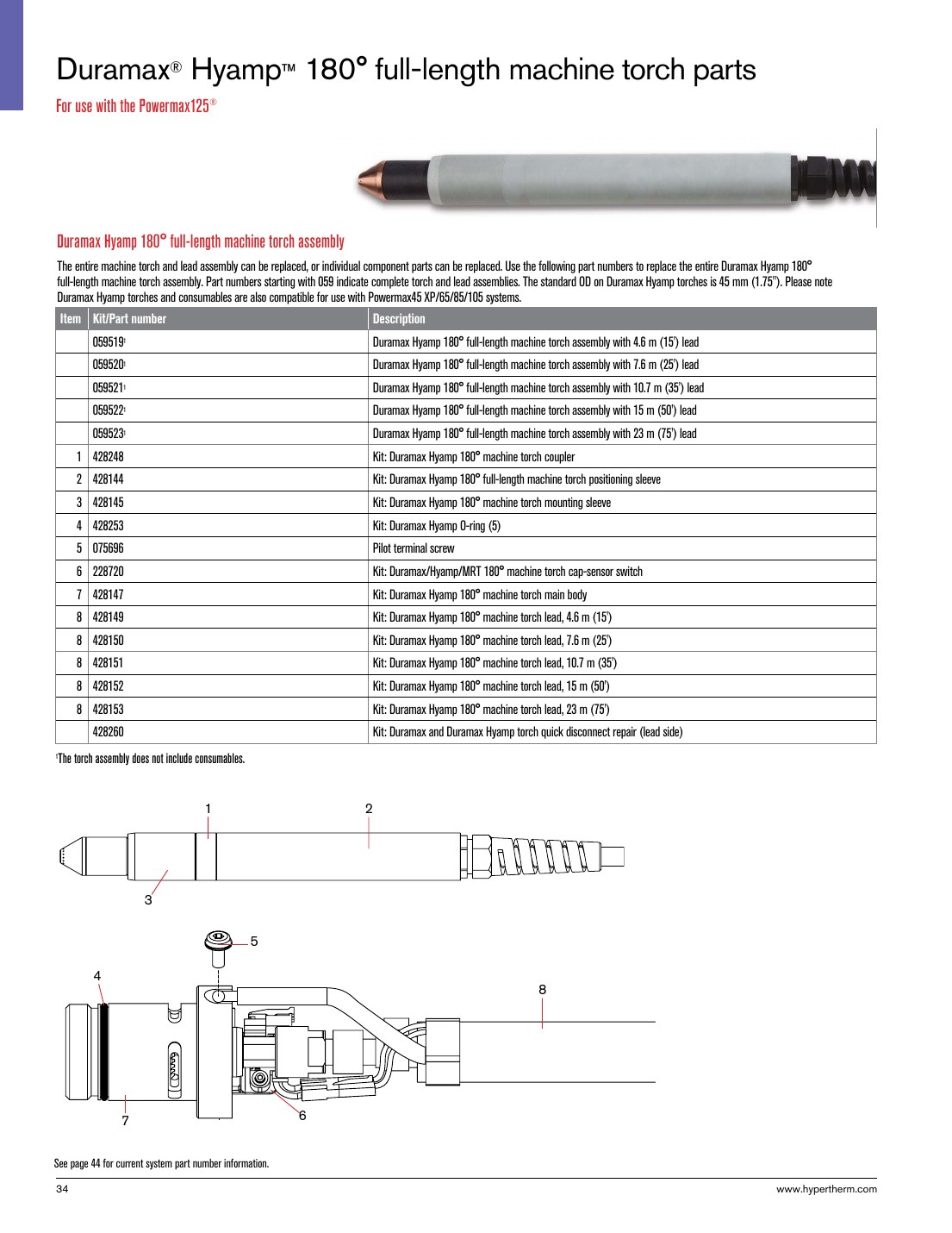
    • Safety glasses and a protective cover are support items, not optional extras.

    Start with the WSP lookup page

    The primary support page for this unit is here: Hobart AirForce 12ci Plasma Cutter Support. The page indicates stock 500564 and lists 120 V specs, XT12R replacement torch, consumable kits, safety glasses, and a protective cover. Treat those listings as the starting point for verification, not as a substitute for checking your exact machine and torch tag.

    Check before you order

    • Inspect the machine label: confirm the model is Hobart AirForce 12ci, not a similar unit.
    • Verify input power: the support page shows 120 V specs. Confirm your unit nameplate and outlet setup match.
    • Inspect the torch tag: confirm whether the unit uses the XT12R replacement torch listed on the support page.
    • Check consumable wear: look for recessed electrode, enlarged nozzle orifice, heat damage, cracks, or unstable arc start.
    • Verify cable and lead condition: cuts, melted sections, or loose strain reliefs can mimic consumable failure.

    Troubleshooting and support checks

    If the cutter is not performing well, the fastest path is a basic inspection sequence. Start simple and document what you find.

    1) No start or weak start

    • Check: power source status, plug condition, and supply voltage at the receptacle.
    • Inspect: trigger switch, torch lead, and any visible torch damage.
    • Verify: the consumables are installed correctly and are not worn beyond serviceable condition.

    2) Arc starts but cut quality is poor

    • Check: air pressure and air quality at the cutter.
    • Inspect: nozzle, electrode, shield, and retaining parts for spatter buildup or heat distortion.
    • Verify: the work clamp is clean and attached to bare metal.

    3) Arc drops out during cutting

    • Check: thermal condition of the machine and duty cycle usage pattern.
    • Inspect: torch lead for intermittent breaks or damaged insulation.
    • Verify: the air supply is steady and dry. Moisture can cause unstable operation and consumable damage.

    4) Consumables wear too quickly

    • Check: cutting technique, standoff distance, and travel speed.
    • Inspect: whether the nozzle is being run beyond normal wear indicators.
    • Verify: you are using the correct consumable kit for the torch family. If uncertain, use Unknown (Verify) until the exact kit is matched.

    Parts lookup buying checks for this model

    For the Hobart AirForce 12ci, the most useful parts categories are torch replacement, consumable kits, and protective items. The support page points to an XT12R replacement torch, but buyers should verify the torch family, connector style, and lead length against the existing machine before ordering. Unknown (Verify) should be used for any detail that is not confirmed by the machine label or the support page.

    Replacement torch check

    • Inspect: the old torch for model markings, connector type, and damage location.
    • Verify: the new torch is listed for the same support page and matches the original torch family.
    • Confirm: no modification is required for fitment unless the manufacturer states otherwise.

    Consumable kit check

    • Inspect: all wear components removed from the torch.
    • Compare: thread shape, size, and seating surfaces.
    • Verify: the kit is intended for the same torch model, not just a similar plasma system.

    Protective gear and cover

    • Check: whether the shop already stocks plasma-rated eye protection.
    • Inspect: the machine’s storage location for dust, slag, and moisture exposure.
    • Verify: a protective cover will not trap heat when the machine is warm after use.

    Use the internal guides as support references

    If the cutter is giving you symptoms beyond basic wear, these related articles can help narrow the fault before you order parts:

    Safety notes

    • Disconnect power before inspecting torch leads, consumables, or internal connections.
    • Use eye protection and hand protection when checking the torch or removing worn parts.
    • Do not use damaged leads, cracked torch bodies, or loose consumable assemblies.
    • Verify ventilation and keep flammables clear of the cutting area.
    • If a part fitment is uncertain, mark it Unknown (Verify) and confirm through the machine label, torch tag, or support listing before use.

    FAQ

    What should I verify first for Hobart AirForce 12ci parts?

    Verify the machine model, input power, and torch family first. Then check consumables, cable condition, and air supply quality.

    Is the XT12R replacement torch listed on the support page the correct part for every unit?

    Unknown (Verify). The support page lists XT12R, but you should confirm the torch tag and connector style on your specific machine before ordering.

    How do I know if the problem is consumables or the torch?

    Inspect the nozzle, electrode, and shield first. If wear is visible or the arc is unstable, consumables are often the first suspect. If the lead, trigger, or torch body is damaged, the torch may need replacement.

    Can I buy based on similar-looking plasma parts?

    No. Similar appearance does not confirm fitment. Match the part to the support page and the machine tag, then verify before purchasing.

    Sources Checked

    Disclosure: As an Amazon Associate, Weld Support Parts may earn from qualifying purchases.
    Related Weld Support Guides

  • Markal 96270, Silver Steak Markal PRO Holder, Pack of (1): Replacement Part Breakdown

    The Markal 96270, Silver Steak Markal PRO Holder, Pack of (1) is best treated as a consumable support item in a marking system, not as a standalone process-critical welding component. For maintenance buyers, shop leads, and support teams, the main question is simple: when a holder starts to fail, what should you inspect before you replace it, and what should you verify after it arrives?

    This guide breaks the part down from a service and support angle. It does not assume undocumented compatibility, dimensions, or internal construction details. Where technical details are not confirmed here, they are listed as Unknown (Verify).

    Key Takeaways

    • The Markal 96270 listing identifies a replacement holder item, but exact internal build details are Unknown (Verify).
    • Before ordering a replacement, inspect the current holder for wear, binding, cracked body parts, or poor lead/marking retention.
    • After receipt, verify fit, actuation, retention, and general condition before putting it into service.
    • Do not assume compatibility with other Markal holders or marking formats unless confirmed by the seller or your internal part records.
    • Use the Amazon product listing only as a product reference point; do not rely on it for undocumented repair guidance.

    What This Part Is Used For

    The product name indicates a Markal PRO holder associated with Silver Steak marking use. In practice, holders in this category are used to secure and present a marking stick or similar consumable in a controlled way. The exact operating method for this specific unit is Unknown (Verify), so support teams should confirm the current tool design before attempting repair, disassembly, or substitution.

    If the holder is being used in a fabrication or maintenance environment, common failure symptoms include poor retention, inconsistent feed, damaged locking features, or a body that no longer holds alignment. Those symptoms do not prove the holder is the only problem. The marking stick, operator handling, storage conditions, or contamination can also be involved.

    Inspection Checklist Before Replacement

    Use this sequence before writing off the holder:

    1. Inspect the body. Look for cracks, bent sections, gouges, or heat damage.
    2. Check retention surfaces. Verify the part still grips the marking material consistently.
    3. Check movement. If the holder has a sliding or advancing function, verify it moves without sticking.
    4. Inspect for debris. Clean out dust, metal fines, and marker residue.
    5. Verify operator handling. Check whether the tool is being dropped, over-tightened, or stored in a way that causes premature wear.

    If any of these checks fail, document the condition with photos and note whether the problem is intermittent or continuous. That record helps avoid repeating the same failure after replacement.

    Troubleshooting Support Steps

    1) Holder will not retain the marking stick

    Check: Confirm the stick type matches the holder’s intended size and format. Exact fit data is Unknown (Verify).

    Inspect: Look for worn jaws, damaged guides, or missing internal parts.

    Verify: Test with a known good marking stick from the same inventory lot if available.

    2) Advancement feels stiff or inconsistent

    Check: Make sure the unit is not loaded with broken fragments or compacted dust.

    Inspect: Examine sliding interfaces for contamination, bending, or corrosion.

    Verify: Clean the holder and repeat the movement test before replacing the unit.

    3) Marking quality has declined

    Check: Confirm the issue is not in the marking material itself.

    Inspect: Review the tip presentation and whether the holder is keeping the stick aligned.

    Verify: Compare output against a known good holder under the same operator and surface conditions.

    Product and Parts Notes

    The only confirmed product detail provided here is the Amazon ASIN reference for the Markal 96270, Silver Steak Markal PRO Holder, Pack of (1): B074WGYF21. No additional specifications, dimensions, or repair kits are verified in the source data available for this draft.

    If you are building a replacement-part record, capture the following internally:

    • Original part name and ASIN reference
    • Observed failure mode
    • Date removed from service
    • Any matching model or lot data from packaging
    • Operator notes on fit, feel, and performance

    Do not assume a “similar” holder will work as a direct substitute unless the vendor or your own verified records confirm it.

    Support and Ordering Considerations

    For buyers, the main risk is ordering on description alone. The product title suggests a specific Markal PRO holder variant, but the available source data does not confirm cross-compatibility with other holder bodies, refill formats, or accessories. Keep that uncertainty in the purchase record and verify against your own approved-use list before standardizing the part.

    If the existing holder is failing repeatedly, review the root cause before replacement. Storage, contamination, impact damage, and incorrect loading are common contributors in marking tool service problems. A replacement part will not fix a handling issue.

    Safety Notes

    • Wear appropriate hand protection when inspecting used marking tools with sharp or worn edges.
    • Do not force a jammed mechanism apart unless the tool design and service method are confirmed.
    • Keep solvents, compressed air, and cleaning methods compatible with your site procedures.
    • Remove the holder from service if cracks, breakage, or loose internal parts are found.
    • Use lockout, housekeeping, and tool-control practices where required by site policy.

    FAQ

    Is this a complete tool or a replacement support part?

    The product name indicates a holder product. Exact internal configuration is Unknown (Verify), so confirm whether your application treats it as a complete tool, a replacement component, or a consumable support item.

    Can I use it with other Markal products?

    Not enough verified data is available here to confirm compatibility. Treat compatibility as Unknown (Verify) unless your internal part records or the seller confirm it.

    What should I check before buying a replacement?

    Inspect the existing holder for wear, binding, damage, and contamination. Verify the marking material type, the loading method, and any model identifiers from the old unit before placing an order.

    What if the new holder still does not work properly?

    Verify the marking stick or consumable, the loading method, and the operator technique. If the failure repeats, document the issue and compare the new part against the removed part for fit and function.

    Sources Checked

    • Amazon product reference provided in the task: Markal 96270, Silver Steak Markal PRO Holder, Pack of (1), ASIN B074WGYF21
    • No WSP lookup page provided
    • No filler metal finder page provided
    • No internal links provided

    Note: This draft intentionally avoids unverified specifications, pricing, certifications, and compatibility claims. Use internal records or supplier confirmation to complete any unresolved technical details.

    Matched Replacement Option

    No products found.

    Disclosure: As an Amazon Associate, Weld Support Parts may earn from qualifying purchases.
  • Hypertherm 851462 Powermax30 AIR Essential Consumable Kit: Replacement Part Breakdown

    The Hypertherm 851462 Powermax30 AIR Essential Consumable Kit is a replacement-part purchase, not a process-change item. Buyers usually need it to keep a handheld plasma system ready for service, reduce downtime, and restore cut quality after normal wear. For support teams and maintenance buyers, the practical question is simple: what is included, what wears first, and what should be checked before the kit is installed?

    This guide focuses on part-level verification and field-use checks. It does not assume any unlisted compatibility beyond the product name provided. If you are matching a machine, torch, or cartridge configuration, verify every identifier against your system documentation before ordering or installation.

    Key Takeaways

    • This is an essential consumable kit for a Powermax30 AIR setup; treat it as wear-part support.
    • Consumables are normal replacement items. Poor cut quality is often a wear issue, not a machine failure.
    • Before use, verify torch model, retaining hardware, and electrode/nozzle condition against your current parts.
    • If the kit contents are not fully confirmed from your source listing, mark the unclear items as Unknown (Verify).
    • Do not force-fit plasma consumables. If the stack-up does not match, stop and confirm the part numbers.

    What to Check Before You Order

    For a consumable kit, the safest buying method is to confirm three points first:

    • Machine identity: confirm the exact plasma unit and torch family in service.
    • Consumable style: confirm whether your torch uses the same electrode, nozzle, shield, and retaining arrangement as the kit you are sourcing.
    • Wear pattern: inspect your current parts and compare the wear to the symptoms on the floor.

    Check: Look for arc instability, rough edge quality, excessive dross, or difficulty transferring arc. These are common reasons crews replace consumables early.

    Inspect: Remove the current tip stack and inspect for pitting, distortion, heat damage, or gas-flow contamination. Examine the torch body for damage that would shorten consumable life.

    Verify: Match the replacement parts to the exact service documents or parts diagram for your setup. If a component cannot be confirmed from the source listing, list it as Unknown (Verify).

    Replacement-Part Breakdown

    The product is identified as an essential consumable kit. That means the useful breakdown is functional, not speculative. In plasma service, the common wear components are typically the electrode, nozzle, shield or deflector, and retaining components. However, the exact contents of this kit should be confirmed from the source listing or packaging.

    • Electrode: Carries the arc load and is a primary wear item.
    • Nozzle: Shapes the arc and affects cut quality and kerf consistency.
    • Shield/deflector: Helps protect the torch and can influence cut standoff behavior.
    • Retaining hardware: Holds the consumable stack in position. Any damage or thread wear can affect retention.

    If the kit contents are not explicitly confirmed by your purchase source, do not assume the stack includes every item above. Mark unknown contents as Unknown (Verify) and cross-check the carton or listing before dispatching it to the field.

    Troubleshooting and Support Checks

    When a plasma cutter starts cutting poorly, do not jump straight to machine repair. Consumables are the first inspection point.

    Check: Inspect the nozzle orifice for enlargement, oval wear, or spatter contamination.

    Inspect: Examine the electrode face for a deep pit or uneven erosion.

    Verify: Confirm that the shield and retaining parts are not cracked, cross-threaded, or seated incorrectly.

    Check: If the arc starts but cuts are inconsistent, verify air quality, line pressure at the machine, and the condition of the consumable stack.

    Inspect: Look for moisture, oil, or debris in the air line and filter path. Contaminated air shortens consumable life.

    Verify: Make sure the torch is assembled in the correct order. A mis-stacked consumable set can create the same symptoms as a worn part.

    Check: If you see repeated consumable burn-back, inspect duty cycle and operating technique.

    Inspect: Review cut travel speed, pierce height, and standoff consistency.

    Verify: Confirm that the operator is using the correct technique for the workpiece thickness and edge condition.

    Product and Parts Section

    Product referenced: Hypertherm 851462 Powermax30 AIR Essential Consumable Kit

    ASIN: B01CSBV3FE

    Amazon affiliate product reference:

    No products found.

    Use this product as a replacement consumable source only. Do not assume it changes the procedure, the duty cycle, or the machine configuration. If your maintenance program requires serialized parts control, record the kit identification and the installation date when the parts are issued.

    Part verification step:

    1. Confirm the machine and torch model in service.
    2. Open the existing consumable stack and compare wear against the replacement parts.
    3. Verify that each part matches the required stack order.
    4. Install only after fit and seating are confirmed.
    5. Test cut on approved scrap material before returning the unit to production.

    Safety Notes

    • De-energize the system before service.
    • Allow hot parts to cool before handling.
    • Wear eye protection and gloves during inspection and replacement.
    • Do not touch electrode or nozzle surfaces with bare hands if contamination control is required by your shop practice.
    • Use approved torch and machine procedures only. Unknown (Verify) settings should not be guessed in the field.

    FAQ

    Q: Is this kit for routine maintenance or repair?
    A: Routine maintenance. Consumables are wear parts and are replaced as performance declines.

    Q: Can I assume the kit fits every Powermax30 system?
    A: No. Verify the exact machine and torch configuration before ordering. Compatibility details not confirmed in the source should be treated as Unknown (Verify).

    Q: What causes consumables to wear out early?
    A: Common causes include poor air quality, incorrect cut technique, excessive pierce abuse, and contaminated or damaged torch components.

    Q: What should I do if the replacement parts do not match my existing stack?
    A: Stop and verify the part numbers against the machine manual, torch diagram, or current packaging before installation.

    Sources Checked

    Note: No raw Amazon URL was used. Any unconfirmed content details remain Unknown (Verify).

    Disclosure: As an Amazon Associate, Weld Support Parts may earn from qualifying purchases.

    Related Weld Support Guides

  • Miller 225671 Tip, ICE- 27C/27T 25Amp, 5 pack: Product Breakdown

    Miller 225671 Tip, ICE- 27C/27T 25Amp, 5 pack: Product Breakdown

    Product not found.
    “>Miller 225671 Tip, ICE- 27C/27T 25Amp, 5 pack

    The Miller 225671 Tip, ICE- 27C/27T 25Amp, 5 pack is a torch consumable package for plasma cutting support work. For buyers and maintenance teams, the key question is not just whether the tip is on the shelf, but whether it matches the torch system, amperage range, and wear pattern your crew is actually running. This part is listed as an extended tip for the ICE-27C plasma cutter torch and is associated with Miller Spectrum 375 and 3765 X-tremes plasma cutters based on the product source provided. Confirm the torch model on the equipment before ordering or installing.

    Key takeaways

    What this part does

    Plasma tips focus the cutting arc and help control cut quality. As the tip wears, cut performance can shift in ways that are easy to spot in the field: rougher edges, more dross, unstable arc starts, or visible damage at the orifice. The right replacement restores the torch’s intended arc shape, but only if the whole consumable stack and torch are in proper condition.

    Because this is a consumable, the buying decision is usually about consistency and uptime. Maintenance teams should stock tips based on actual torch usage, not only on machine count. If a torch is heavily used on production cuts, tips should be treated as planned replacement items, not emergency parts.

    Check, inspect, verify before install

    Use this sequence before installing a new tip:

    1. Check the torch model. Confirm the torch is ICE-27C or ICE-27T as applicable to your setup. If the torch designation is unclear, mark it as Unknown (Verify) and stop until the model is confirmed.
    2. Inspect the consumable stack. Look at the electrode, shield, swirl ring, retaining hardware, and tip seat. A new tip will not correct damage elsewhere in the stack.
    3. Verify amperage use. The product title identifies 25Amp. Verify your operating setup against the torch and machine manual before use.
    4. Check for heat and contamination. Carbon, spatter, moisture, and torch body damage can shorten tip life. Clean the torch components only according to the machine manual.
    5. Verify correct seating. Install the tip fully and evenly. If seating feels inconsistent, stop and inspect the torch body and mating parts.

    Troubleshooting support for poor cut quality

    If cut quality drops after a tip change, do not assume the new tip is defective. Work through the torch system first.

    Problem: rough edge or heavy dross

    Problem: unstable arc or hard starts

    Problem: repeated short tip life

    Parts and application notes

    This product listing identifies the part as a Miller consumable for the ICE-27C torch, with application to Miller Spectrum 375 and 3765 X-tremes plasma cutters per the source data provided. That is the safest level of identification available here. Any further compatibility detail is Unknown (Verify) until checked against the machine manual, torch label, or internal maintenance record.

    For buyers, the main control points are straightforward:

    How maintenance teams should stock it

    Consumables like this tip are best managed with a simple issue-and-replace process. Keep the package sealed until needed, label inventory by torch family, and separate plasma consumables by system if your shop uses more than one torch platform. Mixing tips by appearance alone is a common cause of downtime. Use the part number and torch designation for stock control.

    If your site uses a formal parts approval process, tie the tip to the machine asset record and the torch serial or family record where possible. If that record is missing, the compatibility status is Unknown (Verify) and should be confirmed before release to production.

    Safety notes

    FAQ

    Is this tip only for the ICE-27C torch?

    The source listing identifies it as an extended tip for the ICE-27C plasma cutter torch. Any use beyond that is Unknown (Verify) and should be checked against the torch and machine documentation.

    Can I use this with a Spectrum 375 or 3765 X-tremes unit?

    The provided source says the torch is on Miller Spectrum 375 and 3765 X-tremes plasma cutters. Verify your exact machine and torch configuration before ordering or installing.

    What should I inspect if the new tip does not improve cut quality?

    Inspect the electrode, shield, swirl ring, torch body, air quality, and operator technique. A new tip alone will not fix wear or contamination elsewhere in the system.

    How should I decide when to replace the tip?

    Replace it when wear is visible, cut quality declines, or the arc becomes unstable. If the condition is uncertain, mark it Unknown (Verify) and inspect the full consumable set.

    Sources checked

    Related Arc Weld Part

    Miller 225671 Tip, ICE- 27C/27T 25Amp, 5 pack

    Miller 225671 Tip, ICE- 27C/27T 25Amp, 5 pack

    Miller 225671 Extended Tips. This is for the ICE-27C plasma cutter torch. Which is on the Miller Spectrum 375 and 3765 X-tremes plasma cutters. Package of 5

    View at Arc Weld Store
  • Listen with Audible