Tag: maintenance

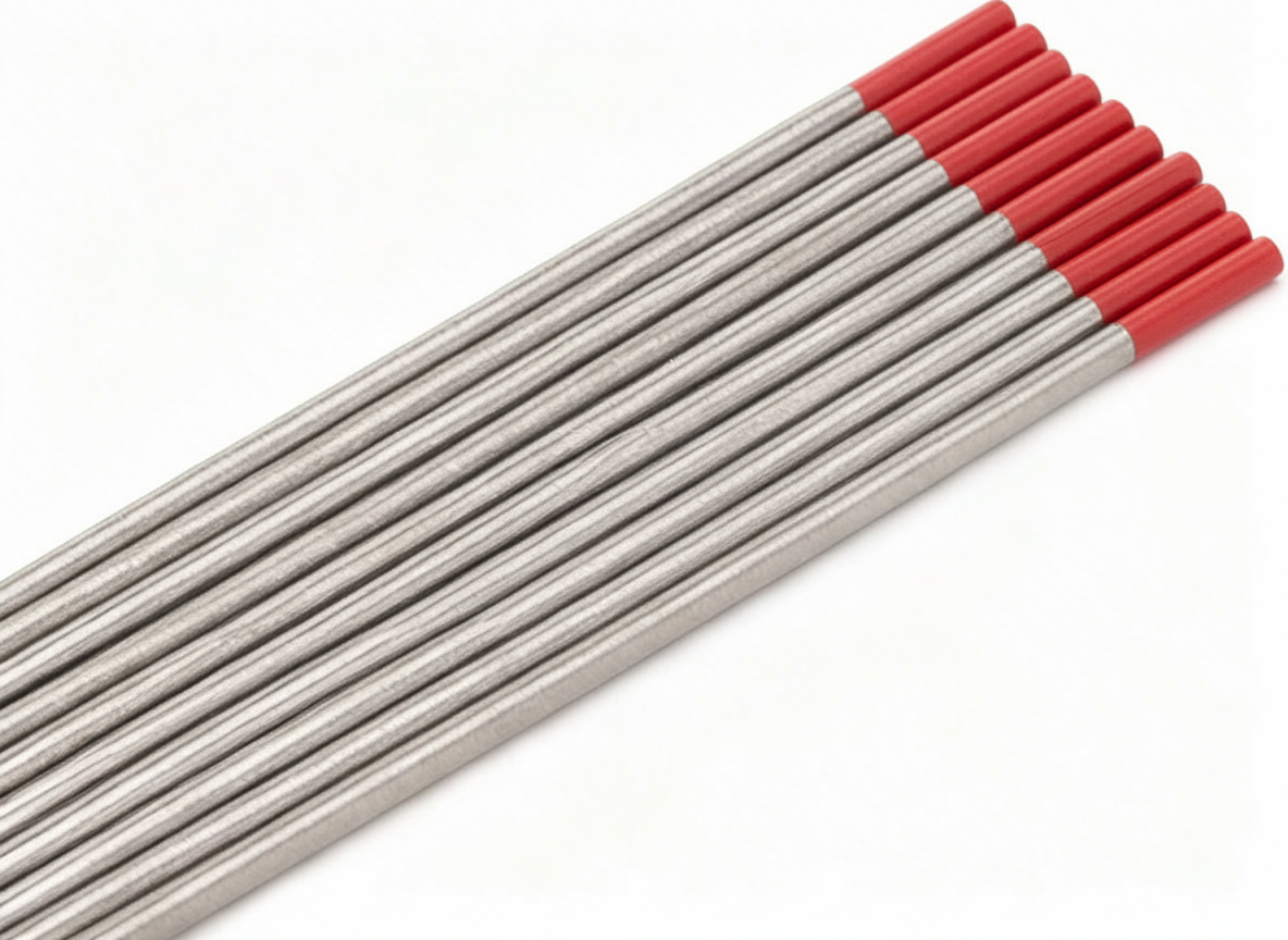
  • Weldmark TIG Collet Body #9, 20, 25 Torch Pk = 5 (13N29-1/8″): Replacement Part Breakdown

    When a TIG torch starts acting up, the collet body is one of the first parts to inspect. A worn or mismatched collet body can cause tungsten slippage, poor gas flow, heat buildup, and inconsistent arc starts. For maintenance buyers and welding support teams, the key is not just replacing a small part, but verifying the torch series, the tungsten size, and the wear condition before the order is placed.

    This breakdown covers the Weldmark TIG Collet Body #9, 20, 25 Torch Pk = 5 (13N29-1/8″) listed under ASIN B0728LD49J. Product naming suggests it is intended for Torch #9, #20, and #25 applications, but final fit should always be confirmed against the torch body, cup, collet, and tungsten setup in service. If your torch uses a different consumable family, do not assume interchangeability.

    Key Takeaways

    • Collet bodies are wear parts. Replace them when the tungsten slips, the bore is deformed, or gas coverage becomes erratic.
    • Check the torch series first. A part listed for #9, #20, and #25 torches may not fit every torch branded as TIG-compatible.
    • Use the tungsten diameter, cup size, and back cap arrangement as verification points before ordering.
    • If the existing part is heat-blued, rounded out, cracked, or packed with debris, treat it as a service failure and inspect the rest of the torch stack.

    What This Part Does

    The collet body holds the collet and tungsten assembly in alignment inside the torch. It also contributes to shielding gas routing through the torch front end. If the bore is worn or contaminated, the tungsten may not clamp properly. That can show up as wandering arc starts, inconsistent stickout, or a tungsten that slowly creeps backward under vibration or heat cycling.

    This is a support component, not a process-setting part. Replacing it does not fix the wrong amperage, the wrong gas, or a poor purge setup. It only restores the mechanical condition needed for normal torch operation.

    Inspect Before You Replace

    Use a flashlight and clean gloves. Remove the cup, collet, tungsten, and back cap. Then work through these checks:

    • Check the bore: Look for oval wear, scoring, or tungsten marking inside the collet body.
    • Inspect the threads: Verify the front-end threads are not stripped, cross-threaded, or packed with spatter and dust.
    • Examine heat damage: Blueing, discoloration, and softened edges can indicate excessive heat or poor gas coverage.
    • Verify collet grip: A loose tungsten after tightening usually means the collet body, the collet, or both are worn.
    • Check for contamination: Grinding dust, oxides, and anti-spatter residue can interfere with gas flow and clamping.

    If the torch has a history of overheating, also inspect the torch head, cable bend relief, gas hose routing, and the regulator flow setting. A consumable failure may be a symptom, not the root cause.

    Troubleshooting Support: Check, Inspect, Verify

    Check: Is the tungsten sliding even after tightening? If yes, confirm the collet size, the collet condition, and the collet body bore.

    Inspect: Compare the removed part to the replacement. Look for length, thread form, and shoulder geometry. Do not rely on appearance alone if the torch family is not known.

    Verify: Match the torch model and the consumable family before installation. If documentation is missing, treat the compatibility as Unknown (Verify).

    Check: Is arc behavior unstable only after torch servicing? That can point to a misassembled front end, damaged insulators, or a missing component.

    Inspect: Confirm the stack-up order from back cap to tungsten. A small assembly error can create gas leaks or poor electrical contact.

    Verify: The cup, collet, collet body, and tungsten size must all belong to the same service configuration.

    Product / Parts Notes

    The product linked for this article is the Weldmark TIG Collet Body #9, 20, 25 Torch Pk = 5 (13N29-1/8″) on Amazon, ASIN B0728LD49J. The registry identifies it as a verified Amazon affiliate product. Specific dimensional and material details were not provided in the source set here, so those remain Unknown (Verify).

    Use the product listing as a parts reference only after you confirm:

    • torch series or torch model
    • tungsten diameter
    • collet body thread and length requirements
    • cup and insulator stack compatibility

    Do not order based on the description alone if your torch is unmarked, heavily modified, or using mixed consumables from more than one family.

    Related Internal Reading

    Safety Notes

    • Disconnect the machine or isolate the torch before servicing consumables.
    • Let the torch cool before handling the front end. Heat damage can make small parts look normal while still being unsafe to touch.
    • Do not force threaded parts together. Cross-threading can ruin the torch head or insulator stack.
    • If shielding gas leaks or the torch runs hot after reassembly, stop and recheck the stack before welding.

    FAQ

    How do I know the collet body is worn?

    Look for a tungsten that no longer holds securely, visible bore wear, burned discoloration, or distorted threads. If the tungsten slips after normal tightening, the part is likely worn or contaminated.

    Can I use this collet body in any TIG torch?

    No. The listing indicates Torch #9, #20, and #25 applications, but the actual torch family must be verified. If the torch model is unknown, treat compatibility as Unknown (Verify).

    Is this a fix for poor arc starts by itself?

    Sometimes, but not always. A new collet body can correct poor tungsten grip or damaged gas routing. It will not fix wrong gas settings, bad tungsten prep, contamination, or a damaged torch cable.

    Should I replace the collet too?

    Yes, inspect it closely. If the collet is flattened, oxidized, or no longer grips well, replace it with the collet body so the front-end stack starts from a known condition.

    Sources Checked

    • Forge OS ASIN registry entry for B0728LD49J
    • Provided Amazon affiliate product shortcode for B0728LD49J
    • Allowed internal links listed for this draft

    Matched Replacement Option

    No products found.

    Disclosure: As an Amazon Associate, Weld Support Parts may earn from qualifying purchases.

    Related Weld Support Guides

  • Thermal Dynamics 8-7503 Tip, 10 pack: Product Breakdown

    Thermal Dynamics 8-7503 Tip, 10 pack: Product Breakdown

    Product not found.
    “>Thermal Dynamics 8-7503 Tip, 10 pack

    The Thermal Dynamics 8-7503 Tip, 10 pack is a plasma cutting consumable for users maintaining compatible Thermal Dynamics systems. This part is listed for the PCH-80 torch and is described as a 40 amp tip. It is also associated with the 625XR, Cutmaster 80XL, Pakmaster 75, Pakmaster 75XL, and Signature PAK625XR. Treat those fitment notes as the starting point for verification, not a substitute for checking the torch, machine, and current consumable chart before installation.

    For maintenance buyers and shop leads, the practical question is not just whether the tip is available. The question is whether the consumable matches the torch body, the amperage setting, and the cut process you actually run. A wrong tip can cause poor arc start, unstable cut quality, excess wear, and unnecessary torch damage. Verify the part number on the old tip, the torch model, and the machine manual before you issue the replacement.

    Key Takeaways

    • Thermal Dynamics 8-7503 is a plasma tip sold in a 10-pack.
    • It is listed for the PCH-80 torch and described as a 40 amp tip.
    • Fitment is stated for 625XR, Cutmaster 80XL, Pakmaster 75, Pakmaster 75XL, and Signature PAK625XR, but you should verify against your manual and torch setup.
    • Consumable life depends on cut current, standoff, air quality, pierce practice, and operator technique.
    • If performance drops, inspect the tip first before replacing larger torch components.

    What this part is used for

    Plasma tips focus and constrict the plasma arc. In service, the tip is a wear item. When the orifice opens up, erodes, or becomes misshaped, cut quality declines. Common signs include rough edges, heavy dross, delayed arc transfer, unstable arc, and visible damage at the tip opening. If you see those symptoms, inspect the full consumable stack, not just the tip.

    Check, inspect, verify before installation

    Check the part number on the packaging and compare it to the torch consumable list. If your removed tip is readable, match the number stamped or identified by your internal records. Do not assume a similar-looking tip is correct.

    Inspect the torch lead, electrode, shield, swirl ring, retaining cap, and any related wear parts. Tip wear may be a symptom of a larger issue such as misaligned assembly, dirty air, or incorrect operating technique. Look for carbon buildup, cracks, ovalization, heat discoloration, and thread damage where applicable.

    Verify the amperage setting and cutting application. A 40 amp tip should be used only where the torch and system documentation support it. If the machine is being run above or below the intended operating range, verify the correct consumable set rather than forcing the current to match the part.

    Troubleshooting support section

    If cut quality is inconsistent, use the tip as the first checkpoint.

    • Check arc start: Verify the electrode and tip are installed correctly and that the torch is fully assembled.
    • Inspect air supply: Moisture, oil, and contamination can shorten tip life. Confirm clean, dry air at the torch input.
    • Verify standoff: Excessive drag or too much gap can accelerate wear. Use the cutting method recommended by the machine maker.
    • Check pierce technique: Aggressive piercing can blow molten material back into the consumables. Review pierce height and delay settings.
    • Inspect the tip orifice: If the opening is enlarged, out of round, or burned, replace the tip and inspect the matching electrode.

    If the same failure repeats after replacement, the root cause is likely upstream. Recheck torch assembly, air quality, power settings, and any process changes introduced before the problem started.

    Product and parts notes

    The available product information identifies this as the Thermal Dynamics 8-7503 Tip, 10 pack. It is described as a part for Thermal Dynamics PCH-80 and as a 40 amp tip. The listed compatible platforms are 625XR, Cutmaster 80XL, Pakmaster 75, Pakmaster 75XL, and Signature PAK625XR. If you are supporting mixed equipment in a maintenance crib, confirm that the torch system in service uses the same consumable family. Unknown (Verify) if your torch revision or retrofit kit changes the required tip stack.

    Because this is a consumable, the value is in repeatable fitment and replacement control. Keep the part number tied to your issue list, not just the machine name. That reduces mis-picks when multiple Thermal Dynamics systems are in the same facility.

    Support checklist for buyers and maintenance teams

    • Confirm the torch model in use.
    • Match the consumable part number to the old tip and current documentation.
    • Verify amperage before release to the floor.
    • Inspect the matching electrode and shield parts for wear.
    • Log air quality and failure mode if tips are failing early.

    Safety notes

    Plasma cutting consumables are part of an energized cutting system. De-energize the machine and allow the torch to cool before service. Do not touch used consumables without verifying temperature. Use eye, hand, and body protection when inspecting torch parts. If the torch shows repeated overheating or unusual wear, remove it from service until the cause is identified.

    FAQ

    Is the Thermal Dynamics 8-7503 Tip, 10 pack a universal plasma tip?
    No. It is listed for specific Thermal Dynamics torch systems. Verify the torch family and consumable chart before use.

    What amp rating is listed for this tip?
    It is described as a 40 amp tip. Verify that this matches your machine setup and application before installation.

    What should I inspect when a tip wears out early?
    Check the electrode, shield, swirl ring, air quality, standoff, and pierce technique. Early tip wear often points to a system issue, not just normal consumable life.

    Can I use the part number alone to confirm fitment?
    Use the part number as the first check, but also verify the torch model and machine documentation. Unknown (Verify) if your setup includes nonstandard torch revisions or retrofit components.

    Sources Checked

    • ArcWeld product page for Thermal Dynamics 8-7503 Tip, 10 pack:
      Product not found.

    Related Arc Weld Part

    Thermal Dynamics 8-7503 Tip, 10 pack

    Thermal Dynamics 8-7503 Tip, 10 pack

    For Thermal Dynamics PCH-80. 40 Amp Tip. 625XR, Cutmaster 80XL, Pakmaster 75, Pakmaster 75XL, Signature PAK625XR. Package of 10

    View at Arc Weld Store
  • KOHLER 47 883 03-S1 Engine Air Filter With Pre-Cleaner Kit: Replacement Part Breakdown

    The KOHLER 47 883 03-S1 Engine Air Filter With Pre-Cleaner Kit is a replacement air intake service item, not a repair for deeper engine problems. For maintenance buyers and shop support teams, the main job is simple: keep dirt out of the engine, match the correct service part, and verify the filter is installed in a way that does not bypass sealing surfaces.

    This guide breaks down the part at a practical level. It is written for inspection, replacement planning, and troubleshooting. It does not assume compatibility beyond the product listing itself. If fitment is uncertain, verify against the engine model, current parts manual, and the equipment serial number before ordering or installing.

    Key Takeaways

    • This is an air filter plus pre-cleaner kit. It is meant for routine intake service.
    • Do not assume universal fit. Verify the engine model and OEM parts listing first.
    • Inspect the air box, sealing surfaces, and intake tract when changing the filter.
    • A dirty pre-cleaner can shorten service intervals, even if the main filter still looks usable.
    • If dirt ingestion is suspected, replace the filter and inspect downstream components before returning the engine to service.

    What This Part Does

    An engine air filter removes airborne dust and debris before it reaches the intake system. The pre-cleaner is a first-stage element that can help trap larger debris before it reaches the main filter. In dusty maintenance environments, both parts matter. A damaged seal, loose housing, or incorrect installation can allow unfiltered air into the engine even if the filter media itself looks acceptable.

    Buyer and Support Checkpoints

    Before ordering or installing the KOHLER 47 883 03-S1 kit, use this check list:

    • Check the engine model number. Do not rely on visual similarity alone.
    • Inspect the current filter dimensions and housing shape. Match against the parts listing and manual.
    • Verify the sealing edge. A distorted seal can be more harmful than a dirty element.
    • Confirm whether the pre-cleaner is included in the service kit. This listing is a kit, but always verify the exact contents at purchase.
    • Check for dust tracking. Powdery dirt downstream of the filter points to bypass or a poor seal.

    Troubleshooting: When to Replace or Inspect Further

    If an engine starts to lose power, runs rich, or shows unusual dust buildup in the intake path, the air filter is one of the first items to inspect. Use the following sequence:

    Check

    • Check the filter media for heavy dust loading, tears, or collapse.
    • Check the pre-cleaner for excessive dirt, oil saturation, or damage.
    • Check the housing for cracks, missing clips, warped covers, or loose fasteners.

    Inspect

    • Inspect the sealing rim and mating surface for sand, debris, or compression set.
    • Inspect the intake tube and clamps for leaks or loose fit.
    • Inspect the old filter for evidence of dirt passing around the element rather than through it.

    Verify

    • Verify the replacement part number against the engine’s official parts record.
    • Verify the filter seats fully and the housing closes without forcing.
    • Verify engine response after service. If performance problems remain, the issue may be fuel, ignition, governor, or mechanical, not the air filter.

    Replacement Part Breakdown

    For maintenance planning, think of this item as three service functions in one package:

    • Main air filter element: Primary barrier for fine particulate.
    • Pre-cleaner: Secondary stage for larger dust and debris.
    • Service fitment: The physical shape and seal interface that must match the engine air box.

    Unknown (Verify): exact media type, dimensions, and engine compatibility. Do not fill those gaps from guesswork. Confirm from the OEM listing or the equipment manual.

    Install and Service Notes

    Use clean hands and a clean work area. Do not tap a damaged filter back into service if the media is torn or the frame is distorted. If the pre-cleaner is reusable on the specific engine setup, inspect it first and follow the OEM service instructions. If service instructions are not available, treat the pre-cleaner as Unknown (Verify) and confirm with the manual.

    Practical install steps:

    1. Shut the engine down and let it cool.
    2. Open the air cleaner housing carefully so debris does not fall into the intake.
    3. Remove the old filter and pre-cleaner.
    4. Clean the housing and sealing surfaces with a dry, lint-free method.
    5. Install the new filter so it seats evenly.
    6. Install the pre-cleaner as specified by the equipment manual, if applicable.
    7. Close the cover and confirm all retainers are secure.
    8. Start the engine and check for abnormal intake noise or leaks.

    Product and Parts Section

    The verified Amazon product associated with this draft is the KOHLER 47 883 03-S1 Engine Air Filter With Pre-Cleaner Kit, ASIN B000H5ZWEC. Use the provided product box for the current listing:

    No products found.

    Do not assume this kit fits every KOHLER-powered machine. Buyer teams should confirm the engine model, serial range, and parts manual before purchase.

    Safety Notes

    • Stop the engine before servicing the air filter.
    • Keep loose dirt out of the intake opening during removal.
    • Do not use compressed air on a filter unless the OEM procedure explicitly allows it.
    • Do not run an engine with a missing filter or open air box.
    • If dust ingestion is suspected, inspect the engine for follow-on wear before placing it back in service.

    FAQ

    How do I know if this is the correct replacement?

    Verify the engine model, the parts manual, and the OEM part number. Do not rely on appearance alone. If any detail does not match, treat fitment as Unknown (Verify).

    Should I replace the pre-cleaner at the same time as the filter?

    For maintenance planning, yes, inspect both together. Replace whichever component is dirty, damaged, or no longer sealing correctly. If the OEM service method is unclear, verify the replacement interval in the manual.

    What if the engine still runs poorly after filter replacement?

    Then the air filter is probably not the only issue. Check fuel delivery, ignition, governor response, intake leaks, and engine condition. Do not keep replacing filters as a substitute for diagnosis.

    Can I use this kit on a different KOHLER engine?

    Unknown (Verify). Use only documented fitment from the OEM parts listing or manual. Similar housings can have different seals and dimensions.

    Sources Checked

    • Provided Amazon product reference: B000H5ZWEC
    • Provided product name: KOHLER 47 883 03-S1 Engine Air Filter With Pre-Cleaner Kit
    • Task instructions and allowed product data only

    Disclosure: As an Amazon Associate, Weld Support Parts may earn from qualifying purchases.

  • Victor Thermal Dynamics 9-8211 Tip 80-Amp, Pack of (1): Product Breakdown

    Victor Thermal Dynamics 9-8211 Tip 80-Amp, Pack of (1): Product Breakdown

    Product not found.
    “>Victor Thermal Dynamics 9-8211 Tip 80-Amp, Pack of (1)

    The Victor Thermal Dynamics 9-8211 Tip 80-Amp, Pack of (1) is a plasma cutting consumable intended for use in supported torch systems. For buyers and maintenance teams, the main question is not just whether the part is available, but whether it matches the torch, current range, and operating system already in service. This breakdown focuses on practical verification steps so you can avoid fit-up issues and premature consumable wear.

    Per the provided product information, this 80-amp tip is best used on SL60 and SL100 torches. It is also described as usable on a plasma cutting torch that performs with virtually all plasma cutting power supplies. The 1Torch is listed as working with high frequency start systems, CD start systems, touch start systems, and moving parts (blow back) start systems. Verify your exact torch model and power source before ordering or installing.

    Key Takeaways

    • Product: Victor Thermal Dynamics 9-8211 Tip 80-Amp, Pack of (1).
    • Reported fit/use: SL60 and SL100 torches.
    • Listed system compatibility for the 1Torch: high frequency start, CD start, touch start, and blow back start systems.
    • Consumable fit and life depend on torch body condition, electrode condition, air quality, and operating technique.
    • Unknown (Verify): exact material composition, dimensional tolerances, and any extended compatibility claims beyond the provided product description.

    Product and Parts Review

    This part is a plasma tip, so it should be treated as a wear item rather than a permanent component. In maintenance planning, tips are normally purchased with other consumables such as electrodes, shields, and retaining parts when applicable. The supplied product description does not list those companion parts, so do not assume a kit configuration. Confirm what your torch head actually uses.

    Before installation, inspect the new tip for obvious defects. Look for damaged threads, distortion, nicks, oval openings, or contamination from storage. If the tip appears damaged, do not install it. Keep consumables clean and dry, and store them in original packaging until needed.

    Check

    • Check the torch model against the tip’s stated fit: SL60 or SL100.
    • Check that the amperage setting aligns with the 80-amp designation.
    • Check the torch head, electrode, and shield components for wear or heat damage.
    • Check air supply quality. Moisture, oil, and dirt can shorten consumable life.

    Inspect

    • Inspect the seating surfaces inside the torch for carbon buildup or arc damage.
    • Inspect the old tip for erosion patterns that may indicate standoff issues, misalignment, or poor air quality.
    • Inspect cable and torch lead condition for cuts, crushed sections, or loose connections.

    Verify

    • Verify polarity and machine setup according to the torch and power source manual.
    • Verify that the start system on the machine matches the torch system type in use.
    • Verify the cut quality after installation using a short test cut before returning the machine to production.

    Troubleshooting and Support Notes

    If the tip installs but the cut is unstable, start with the basics. Consumable issues are often caused by setup, not the part alone. Use the following checks in sequence.

    Arc starts but cut quality is poor

    • Check whether the tip is the correct size and type for the torch.
    • Inspect the electrode. A worn electrode can mimic a bad tip.
    • Verify air pressure and dryness. Unknown (Verify): the exact pressure range for your system.
    • Confirm the work clamp connection and workpiece contact area.

    Tip wear is faster than expected

    • Check for excessive amperage or prolonged pierce time.
    • Inspect technique. Excessive standoff or dragging the tip can shorten life.
    • Verify that the torch is not being operated outside the machine’s rated procedure.
    • Inspect for unfiltered moisture or oil in the air line.

    Tip will not seat correctly

    • Inspect the threads and retaining surfaces for damage.
    • Verify that the torch model is actually SL60 or SL100, not a similar-looking variant.
    • Remove debris from the torch head and recheck fit by hand. Do not force installation.

    WSP Lookup Section

    No WSP lookup page was provided for this draft, so no source-based lookup link is included here. If you need a cross-reference check, use the approved WSP lookup tool available in your internal workflow before procurement.

    Buyer and Maintenance Guidance

    For buyers, the main control point is fit confirmation. An 80-amp plasma tip is only useful if it matches the torch body, consumable stack, and current setting. For maintenance teams, the better approach is to standardize by machine family and keep a small approved consumable list by torch type. That reduces installation errors and keeps replacements predictable.

    When ordering this part, confirm the exact torch model from the machine label, torch tag, or service record. Do not rely on appearance alone. Similar torches can use different consumable designs. If documentation is missing, compare the removed tip with the replacement and verify against the torch manual before use.

    Safety Notes

    • Disable power before servicing the torch or replacing consumables.
    • Allow hot parts to cool before handling.
    • Use eye protection and gloves when inspecting used consumables.
    • Never force a part into the torch head.
    • Follow the machine and torch manufacturer procedures for startup, piercing, and cut distance.
    • Unknown (Verify): any torch-specific insulation or handling precautions not stated in the provided product information.

    FAQ

    Is the Victor Thermal Dynamics 9-8211 Tip 80-Amp compatible with SL60 and SL100 torches?

    Based on the provided product description, yes. It is listed as best used on SL60 and SL100 torches. Verify against your exact torch revision before installation.

    Can this tip be used on all plasma cutting power supplies?

    The provided description says it can be used on a plasma cutting torch that performs with virtually all plasma cutting power supplies. Do not treat that as a blanket approval. Verify your machine, torch, and start system before use.

    Does the 1Torch work with different start systems?

    The supplied information states that the 1Torch works with high frequency start systems, CD start systems, touch start systems, and moving parts (blow back) start systems. Confirm this against the exact torch model in your shop.

    What should I inspect first if cut quality drops after replacing the tip?

    Inspect the electrode, air quality, torch seating surfaces, and amperage setting first. A new tip will not correct a worn electrode, bad air, or an incorrect machine setup.

    Sources Checked

    • Provided ArcWeld product source: Victor Thermal Dynamics 9-8211 Tip 80-Amp, Pack of (1)
    • Provided product description text in the task payload

    Final note: treat this tip as a consumable matched to a specific torch family. Verify the torch model, start system, and operating setup before ordering or installing.

    Related Arc Weld Part

    Victor Thermal Dynamics 9-8211 Tip 80-Amp, Pack of (1)

    Victor Thermal Dynamics 9-8211 Tip 80-Amp, Pack of (1)

    Victor Thermal Dynamics 9-8211 Tip 80 Amp best to be used on SL60 and SL100 torches. This tip can be used on the plasma cutting torch that performs with virtually all plasma cutting power supplies. The 1Torch works with high frequency start systems, CD start systems, touch start systems and moving parts (blow back) start systems. Pack of 1 each

    View at Arc Weld Store
  • Kohler Nut Wing #KOH-12 100 01-S: Replacement Part Breakdown

    The Kohler Nut Wing #KOH-12 100 01-S is a replacement part reference that maintenance buyers and shop support teams may encounter when servicing equipment with Kohler components. For a wing nut, the important question is not just the part name. It is whether the thread, material condition, clamping face, and fit match the application you are repairing. If any of those points are uncertain, verify before installation.

    This draft keeps the focus on practical identification and support steps. It does not assume compatibility beyond the part reference provided. For equipment-specific use, confirm the machine model, thread match, and assembly requirements against the OEM documentation or an authorized parts source.

    Key Takeaways

    • Use the exact part reference when ordering or cross-checking: Kohler Nut Wing #KOH-12 100 01-S.
    • Do not assume fit from the part name alone. Verify thread, diameter, pitch, and seating style.
    • Inspect the mating stud or bolt before replacing the wing nut. A damaged stud will cause repeat failure.
    • If the application is on a machine or service panel, check for vibration, heat, corrosion, and hand-tightening requirements.
    • When details are unknown, mark them as Unknown (Verify) rather than guessing.

    What This Part Reference Tells You

    A wing nut is typically used where hand removal or frequent access is needed. The Kohler part reference suggests an OEM-style replacement component, but the reference alone does not confirm the thread size, finish, or material. Those details matter in field service because a wing nut that starts on the thread but does not seat correctly can loosen, gall the stud, or fail under vibration.

    If you are tracking down the correct replacement, document the following before you order:

    • Equipment model and serial number
    • Location of the fastener on the machine
    • Visible thread size and pitch, if measurable
    • Old part condition: intact, stripped, cracked, corroded, or heat damaged
    • Any washer, lock element, or spacer used with the nut

    Troubleshooting and Support Checks

    Use a simple inspect-verify routine before installing a replacement wing nut.

    Check

    • Check the removed nut for thread wear, flattening, cracks, and corrosion.
    • Check the stud or bolt for damaged crests, mushrooming, or cross-thread marks.
    • Check the mating surface for burrs, distortion, or debris that can prevent full seating.
    • Check whether the application is hand-tightened only or exposed to repeated vibration.

    Inspect

    • Inspect the thread start on the replacement part. The first few turns should not show deformation.
    • Inspect for any contamination such as paint, rust, or metal chips in the female or male thread.
    • Inspect nearby hardware for signs of looseness that could indicate a larger fastener issue.

    Verify

    • Verify thread match by measuring or test-fitting by hand. Do not force engagement.
    • Verify clearance around the wing tips so the nut can be turned without interference.
    • Verify the retained assembly still closes, clamps, or secures correctly after tightening.
    • Verify that any replacement maintains the same service access and does not interfere with covers or guards.

    If the wing nut begins to bind immediately, stop and recheck the thread. Cross-threading can damage both the nut and the stud. If the part spins freely but never tightens, the thread pitch or diameter may not match, or the stud may already be worn beyond serviceable condition.

    Replacement Part Breakdown

    For service planning, break the replacement decision into four parts:

    1. Identification: Confirm the exact part reference on the existing machine record or removed hardware.
    2. Fit: Confirm thread size, thread pitch, and required seating style. Unknown (Verify) if not documented.
    3. Condition of mating hardware: Replace or repair the stud, bolt, washer, or panel hardware if damaged.
    4. Application demands: Consider vibration, temperature, contamination, and frequency of removal.

    This is the point where many repair jobs go wrong. A wing nut is often treated as a generic item, but in maintenance work the wrong fastener can create repeat service calls. The cost of verifying fit is lower than repairing a stripped stud or a loose cover.

    Product / Parts Section

    The provided product reference is:

    • Product name: Kohler Nut Wing #KOH-12 100 01-S
    • ASIN: B00CSBT27G
    • Amazon affiliate shortcode:

      No products found.

    No compatibility, dimensions, material grade, or certification details are confirmed in the source data provided here. Treat those details as Unknown (Verify) until checked against the OEM parts documentation or the product listing from the approved source.

    Safety Notes

    • Lock out and tag out equipment before removing guards, covers, or retained assemblies when required by site procedure.
    • Do not substitute a wing nut in a load-bearing or critical retention point unless the application specifically allows it.
    • Do not force mismatched threads. Forced installation can damage the fastener and nearby components.
    • If corrosion is present, use appropriate eye protection and hand protection when cleaning or removing hardware.

    FAQ

    Is the Kohler Nut Wing #KOH-12 100 01-S a universal replacement?

    No. The part reference alone does not prove universal fit. Verify the thread, size, and application before use.

    What should I do if the new wing nut will not start by hand?

    Stop and inspect the stud or bolt for damage, contamination, or incorrect thread pitch. If needed, confirm the replacement against the OEM parts record. Do not force it.

    Can I reuse the old stud if the wing nut was stripped?

    Only if inspection shows the stud is still in serviceable condition. If the threads are flattened, galled, or deformed, replace the stud or related hardware as required.

    What details are still unknown?

    Material, finish, exact dimensions, and application-specific compatibility are Unknown (Verify) based on the provided source data.

    Sources Checked

    • Provided Amazon product reference for Kohler Nut Wing #KOH-12 100 01-S
    • Provided ASIN registry reference: B00CSBT27G

    Use this part only after fit and application checks are complete. For maintenance purchasing, the safest path is to confirm the mating hardware and the equipment model before release to the field.

    Disclosure: As an Amazon Associate, Weld Support Parts may earn from qualifying purchases.

  • AN RG-300-12 36″ ROD GUARD, Pack of (1): Replacement Part Breakdown

    Rod storage looks simple until consumables get damaged, contaminated, or misplaced on the job. The AN RG-300-12 36″ Rod Guard, Pack of (1) is listed here as a replacement part reference for buyers and maintenance teams that need a basic storage or protection component for stick electrodes. The key question is not just whether it exists, but whether it matches the way your crew stores rods, handles boxes, and moves material between the bench, the truck, and the jobsite.

    This guide focuses on replacement-part breakdown, what to inspect before ordering or installing, and how to verify that the part belongs in your support setup. Any unconfirmed technical detail should be treated as Unknown (Verify).

    Key Takeaways

    • The product is identified as AN RG-300-12 36″ ROD GUARD, Pack of (1), ASIN B00VJ3A0CK.
    • Use this as a replacement part verification step, not as a substitute for confirming fit.
    • Do not assume rod diameter, closure style, mounting method, or material construction. If not documented in your source data, mark it Unknown (Verify).
    • Inspect the surrounding storage system, not just the guard itself. Damage often comes from impact, heat, or poor handling.
    • For purchasing teams, confirm the guard against the current asset list, carton labeling, and any internal maintenance record before release.

    What This Part Is Used For

    A rod guard is generally used to protect welding electrodes or related consumables during storage and handling. In a stick welding environment, that matters because rod condition affects usability. Moisture, contamination, bent packages, and crushed containers can create waste and slow the work.

    For this specific listing, treat the function as a storage-protection component and verify all details that affect fit or use. If your operation relies on a particular holder, tube, bracket, or carry method, compare the guard to the existing unit before purchase.

    Replacement Part Breakdown: What to Check

    Before you approve this item as a replacement, work through a short breakdown process.

    1) Identify the Existing Part

    • Check the current rod guard or storage tube for visible part markings.
    • Inspect the overall length and physical configuration of the installed item.
    • Verify whether the old part was damaged by impact, heat, wear, or missing hardware.

    2) Confirm the Storage Requirement

    • Check whether the crew needs a guard for daily transport, bench storage, or long-term electrode protection.
    • Inspect the environment for moisture, dust, and physical handling risk.
    • Verify whether your process requires a sealed tube, open guard, or another form of protection. Unknown (Verify) if not documented.

    3) Match the Replacement to the Application

    • Check the current mounting or carry method.
    • Inspect the replacement part dimensions against the removed part.
    • Verify that the replacement does not interfere with adjacent tools, holders, or storage racks.

    Troubleshooting Before You Buy

    When a rod guard is being replaced, the failure may not be the guard alone. Use this support checklist.

    If Rods Are Getting Dirty or Damaged

    • Check the guard for cracks, open seams, or missing caps.
    • Inspect the storage area for contact with grinding dust, oil, or moisture.
    • Verify whether rods are being returned to a dry storage location after use.

    If the Guard Was Lost or Mixed Up

    • Check jobsite labeling and inventory records.
    • Inspect the purchase history and part number references.
    • Verify the actual replacement before installation or issue to the crew.

    If the Part Does Not Fit

    • Check whether the original part was modified.
    • Inspect the replacement against the original part side by side.
    • Verify dimensions, mounting points, and closure method directly from the source listing or receiving paperwork. Unknown (Verify) if not stated.

    Product and Parts Reference

    The available product reference for this article is the Amazon-registered item below. Use it as a procurement reference only after fit and application checks are complete.

    AN RG-300-12 36″ ROD GUARD, Pack of (1)
    ASIN: B00VJ3A0CK
    Amazon shortcode:

    No products found.

    Do not assume compatibility with every rod storage setup. The identifying information confirms the listing, not your specific application. If you manage multiple stick welding stations, compare the old part, the equipment record, and the receiving label before ordering extras.

    How Maintenance Buyers Should Verify the Part

    For purchasing and maintenance teams, the best process is simple and repeatable:

    1. Check the ASIN or item reference against the approved part list.
    2. Inspect the old component, including length, shape, and attachment points.
    3. Verify the replacement against the same physical sample or drawing.
    4. Confirm the issue date of the order and the job location.
    5. Document any unknown details as Unknown (Verify) instead of guessing.

    That process prevents false matches and reduces returns. It also helps when a part number is referenced informally by the crew but not tied to a controlled asset record.

    Safety Notes

    • Keep electrode storage dry and away from contaminants.
    • Do not use a damaged guard if it cannot protect the rods from dirt, impact, or moisture.
    • Handle welding consumables according to site procedure and the manufacturer’s instructions for the rod type in use.
    • If any feature of the guard is not clearly documented, treat it as Unknown (Verify) before field use.

    FAQ

    Is this a consumable or a replacement support part?

    It is treated here as a replacement support part for rod storage and handling. Verify the exact role in your setup before purchase.

    Can I assume the rod size or mounting method from the product name?

    No. The product name includes “36″,” but any more detailed fit, mounting, or compatibility information is Unknown (Verify) unless it is confirmed in the source listing or your internal records.

    What should I compare before ordering?

    Compare the old part, any part number on the asset, the physical length, the attachment method, and the storage application. If any item is unclear, mark it Unknown (Verify).

    Can this guide confirm procedure approval for specific electrodes?

    No. It is a buyer and replacement-part guide only. Procedure approval, electrode handling, and storage requirements must come from your welding procedure, site rules, or manufacturer documentation.

    Sources Checked

    • Allowed Amazon product reference: AN RG-300-12 36″ ROD GUARD, Pack of (1), ASIN B00VJ3A0CK
    • Provided internal link review for stick welding support context
    • No WSP lookup page was provided in the allowed sources for this task
    • No filler metal finder page was provided in the allowed sources for this task

    Related reading: Welding Electrode Holder: Stinger Guide & Stick Welding Tips

    Related reading: Welding Electrode Holder: Choose the Best for Stick Welding

    Related reading: Stick Welding Arc Blow Causes and Fixes: Magnetic Arc Deflection, Ground Clamp Placement, AC/DC Settings, and Weld Sequence

    Disclosure: As an Amazon Associate, Weld Support Parts may earn from qualifying purchases.

    Related Weld Support Guides

  • CGW 45001, Cut-Off Wheel 4″ x 5/8″, Type 27, Pack of (25): Product Breakdown

    CGW 45001, Cut-Off Wheel 4″ x 5/8″, Type 27, Pack of (25): Product Breakdown

    Product not found.
    “>CGW 45001, Cut-Off Wheel 4" x 5/8", Type 27, Pack of (25)

    The CGW 45001 cut-off wheel is a small-diameter abrasive wheel intended for cutting tasks in metal fabrication and maintenance work. The listed product data identifies it as a 4-inch wheel with a 5/8-inch center hole, Type 27 form, and pack quantity of 25. The available source data also identifies zirconia aluminum oxide abrasive, 60 grit, medium grade, and a maximum speed of 19,000 RPM. Use those details as the starting point for selection, setup, and inspection. Do not assume more than the source confirms.

    Key Takeaways

    Product Breakdown

    The source product listing for CGW 45001, Cut-Off Wheel 4″ x 5/8″, Type 27, Pack of (25) identifies it as a CGW Abrasives wheel built with zirconia aluminum oxide abrasive. The wheel size is 4 inches in diameter with a 5/8-inch center hole. The wheel type is Type 27. Grit is listed as 60 and grade as medium. Maximum speed is listed as 19,000 RPM.

    That combination points to a wheel intended for general cutting support in shop and field maintenance work. The source specifically mentions cutting carbon and stainless steels. Anything beyond that is Unknown (Verify).

    How to Check Fit Before Use

    Before mounting this wheel, verify the grinder and accessory interface. Cutting wheel failures often start with the wrong size, wrong flange setup, or a damaged tool.

    Installation and Setup Checks

    Use a simple pre-use routine. This helps reduce runout, wobble, and early wheel damage.

    1. Disconnect power before changing the wheel.
    2. Remove the old wheel and clean both flanges.
    3. Inspect the spindle, nut, and guard for damage.
    4. Install the new wheel without forcing it onto the arbor.
    5. Seat the wheel evenly between the flanges.
    6. Snug the retaining nut to the tool maker’s instructions. Do not overtighten.
    7. Spin the wheel by hand and verify it clears the guard and does not contact the work support.
    8. Run the tool briefly at no load and verify no abnormal vibration, noise, or wobble.

    Troubleshooting Cutting Problems

    If the wheel is not cutting cleanly, do not assume the wheel is defective. Check the setup and the work process first.

    Problem: Wheel vibrates or wobbles

    For more detail on vibration causes, see Cut-Off Wheel Vibration Troubleshooting: Grinder Wobble, Wheel Runout, Flange Problems, and Unsafe Cutting Symptoms.

    Problem: Slow cut or excessive pressure needed

    Problem: Wheel wears faster than expected

    How to Evaluate Whether This Wheel Fits the Job

    Maintenance buyers and supervisors should compare the task to the source data rather than rely on general assumptions. Use this wheel as a candidate when you need a 4-inch Type 27 wheel with a 5/8-inch bore and a 19,000 RPM limit. The source says it is for carbon and stainless steels. If the job involves another alloy, a different grinder class, or a special cutting method, verify compatibility before issue.

    If you need help understanding Type 1 versus Type 27 cut-off wheel selection, review Type 1 and Type 27 Cut-Off Wheels: Pros, Cons, and Applications.

    Safety Notes

    FAQ

    Is the CGW 45001 wheel for stainless steel?
    The source listing states it is for cutting carbon and stainless steels. Verify the exact stainless grade and job conditions before use.

    What grinder does it fit?
    The source provides a 5/8-inch center hole and a 4-inch diameter. Exact tool compatibility is Unknown (Verify). Match the arbor, guard, and speed rating to the grinder manufacturer’s instructions.

    Can this wheel be used above 19,000 RPM?
    No. The source lists a maximum of 19,000 RPM. Do not exceed that value.

    What does Type 27 mean here?
    Type 27 is the wheel form listed by the source. Use it only when the grinder, guard, and application are suitable. For a broader breakdown of Type 27 use, verify against the tool and wheel manufacturer data.

    Sources Checked

    Note: All uncertain compatibility and application details are marked as Unknown (Verify). Do not infer approvals or certifications not stated in the source data.

    Related Arc Weld Part

    CGW 45001, Cut-Off Wheel 4" x 5/8", Type 27, Pack of (25)

    CGW 45001, Cut-Off Wheel 4" x 5/8", Type 27, Pack of (25)

    CGW Abrasives 45001 Cut-Off Wheel 4" x 5/8" 60 Grit Type 27 Zirconia Aluminium Oxide General purpose cutting wheel. Zirconia grain for faster cutting and longer life. For cutting carbon and stainless steels. Specification: BRAND: CGW Abrasives ABRASIVE MATERIAL: Zirconia Aluminum Oxide GRIT: 60 GRADE: Medium DIAMETER INCHES: 4 CENTER HOLE DIAMETER INCHES: 5/8 MAX RPM: 19000 WHEEL TYPE: Type 27 TOOL COMPATIBILITY:…

    View at Arc Weld Store

    Related Weld Support Guides

  • Hypertherm Air T30 Torch Parts Breakdown: Parts Lookup and Buying Checks

    Hypertherm Air T30 Torch Parts Breakdown: Parts Lookup and Buying Checks

    Hypertherm Air T30 Torch Parts Breakdown

    The Hypertherm Air T30 torch support path is a parts-lookup problem before it is a buying problem. For maintenance buyers and weld shop support teams, the main risk is ordering a consumable or service part by name instead of confirming the torch family, cut mode, and part interface. The result is wasted time, mismatched hardware, or a torch that will not assemble correctly.

    This guide is a practical breakdown for the Hypertherm Air T30 Torch Parts Breakdown process. It focuses on what to inspect, what to verify before ordering, and how to use the Weld Support Parts lookup page as a starting point for parts identification.

    Key Takeaways

    • Start with torch family identification, not the cut tip alone.
    • Verify retaining hardware, shield style, nozzle style, and electrode condition before ordering.
    • Do not assume compatibility from a similar Hypertherm torch name.
    • Use the WSP lookup page as the source page for parts identification, then confirm against the torch in hand.
    • When a detail is uncertain, mark it as Unknown (Verify) and confirm from the machine, torch label, or service documentation.

    What the Air T30 Parts Breakdown Should Cover

    For a torch service check, the useful breakdown is the set of wear parts and torch-side service items that affect arc start, cut quality, and torch assembly. That usually includes the electrode, nozzle, shield or drag shield style if used, retaining cap or retaining hardware, swirl ring or gas distribution component if used, and any torch body or lead-side service items that are specific to the torch family.

    For this support path, the source page is the place to begin the lookup:

    Hypertherm Air T30 hand torch support on Weld Support Parts

    Use that page to identify the support path, then verify the exact torch and consumable set before placing an order.

    Check the Torch Before You Buy

    Do not order from memory. A fast visual inspection often prevents the wrong part from being purchased.

    • Check the torch label. Confirm the torch family and any visible model marking. If unreadable, note it as Unknown (Verify).
    • Inspect the retaining hardware. Verify whether the cap, shield, or front-end hardware matches the torch you have in service.
    • Inspect the nozzle and electrode wear. Look for pit wear, heat discoloration, erosion, and arc damage.
    • Verify the front-end stack-up. Count the parts in the assembly as removed, and compare that stack to the lookup page or service parts breakdown.
    • Check for cut-quality symptoms. Heavy dross, arc wandering, or repeated pilot-arc issues may indicate worn consumables rather than a power supply fault.

    Troubleshooting Support: Where Parts Checks Matter

    Many torch problems look electrical at first but are actually consumable-related. Before replacing components upstream, inspect the torch front end.

    1) No-start or weak start

    • Inspect the electrode and nozzle for obvious wear or burn damage.
    • Verify the torch stack is assembled correctly and tightened to the correct feel for the design, not over-torqued.
    • Check for contamination, moisture, or debris in the torch front end.

    2) Pilot arc dropout

    • Inspect the retaining hardware and front-end fit.
    • Verify the consumables are the correct family for the Air T30 support path.
    • Check lead condition, damage at the torch neck, and any visible burn-through.

    3) Poor cut quality

    • Inspect nozzle orifice wear and edge damage.
    • Verify the shield or drag shield style against the torch setup in use.
    • Check the work clamp, air quality, and cut technique before replacing parts again.

    For a deeper fault tree, the internal support article on pilot arc issues is a useful follow-up:

    Plasma Cutter Pilot Arc Failure Troubleshooting

    Buying Checks for Service Parts

    When you move from inspection to purchasing, treat every line item as a verification step.

    • Check part family first. The torch family must match the support path.
    • Inspect the old part. Compare shape, thread style, contact surfaces, and overall length. If the old part is damaged beyond comparison, mark the detail Unknown (Verify).
    • Verify the assembly count. Some torch fronts use multiple small parts that are easy to miss.
    • Confirm the use case. Drag cutting, standoff cutting, or shielded use may require different front-end hardware. If not confirmed, the requirement is Unknown (Verify).
    • Do not substitute by brand alone. Similar plasma parts are not interchangeable without verification.

    If you need a methodical way to compare drag-shield and front-end configurations, use this internal reference:

    Plasma Drag Shield Compatibility Guide

    WSP Lookup Section

    Use the Weld Support Parts lookup page as the starting point for the Air T30 support path:

    View the Hypertherm Air T30 hand torch support page

    Practical workflow:

    1. Open the lookup page.
    2. Match the torch family to the machine and torch in service.
    3. Remove and inspect the worn parts.
    4. Compare the old parts to the page listing and any internal support notes.
    5. Only then place the order.

    Any item that cannot be confirmed from the torch, the page, or service paperwork should remain Unknown (Verify) until checked.

    Safety Notes

    • De-energize the plasma system before removing torch parts.
    • Allow the torch to cool before handling front-end consumables.
    • Do not inspect burned parts by touch immediately after use.
    • Use eye protection when cleaning the torch front end.
    • Do not mix unknown parts into a live torch assembly.

    FAQ

    How do I know if the Air T30 part I need is a consumable or a service part?

    Check the wear pattern and location. Front-end items such as electrodes, nozzles, shields, and retaining hardware are consumable-facing. Torch-body, lead-side, or connector items are service parts. If the category is unclear, label it Unknown (Verify) and compare against the lookup page.

    Can I order by torch name only?

    No. Torch name alone is not enough. Verify the exact torch family, front-end stack, and cut mode before ordering.

    What should I do if the old part is too damaged to identify?

    Use the torch label, machine model, and the support page as reference points. If a detail still cannot be confirmed, keep it as Unknown (Verify) until checked against service documentation or a known-good assembly.

    Why does a torch sometimes fail even when the power supply is fine?

    Worn or mismatched consumables can cause no-start, weak arc, dropout, and poor cut quality. Start with the torch front end before replacing larger components.

    Sources Checked

    Disclosure: As an Amazon Associate, Weld Support Parts may earn from qualifying purchases.

    Related Weld Support Guides

  • S19417 Lincoln Style Nozzle Insulator – Arc Weld by Masterweld Pack of (2): Product Breakdown

    S19417 Lincoln Style Nozzle Insulator – Arc Weld by Masterweld Pack of (2): Product Breakdown

    Product not found.
    “>S19417 Lincoln Style Nozzle Insulator - Arc Weld by Masterweld Pack of (2)

    The S19417 Lincoln Style Nozzle Insulator – Arc Weld by Masterweld Pack of (2) is a MIG support part meant for a specific torch-component stack. According to the product source, it is a Lincoln style nozzle insulator, it is used with the S19418 gas diffuser, and it does not work with PRO series equipment. That is the core buying point: this is a fitment-sensitive part, not a universal consumable.

    For welders and maintenance buyers, the practical question is not only “what is it?” but “will it match the torch setup already in service?” This article keeps the focus on verification steps, fit checks, and support-side troubleshooting before the part is installed into production use.

    Key Takeaways

    What This Part Does

    A nozzle insulator sits in the consumable stack and helps isolate and position the nozzle assembly relative to the diffuser and contact area. In practical shop use, that means the part needs to match the torch design closely. If the geometry is wrong, the nozzle may not seat correctly, or the assembly may not maintain the intended spacing.

    Because the source data only confirms the Lincoln style designation, the S19418 diffuser pairing, and the PRO series exclusion, any deeper compatibility claims are Unknown (Verify). Do not assume it will interchange with all Lincoln-pattern MIG guns or all aftermarket diffuser designs.

    Buyer Check: Before You Order

    Installation and Support Checks

    Use the following checks during replacement and return-to-service:

    If the nozzle will not seat, do not grind the insulator to make it fit. That usually indicates a mismatch in the torch system, a worn diffuser, or the wrong consumable family. Unknown (Verify) for any workaround not stated in the source.

    Troubleshooting Support

    Problem: Nozzle will not seat correctly

    Problem: Consumable life is short

    Problem: Replacements do not match the old part

    Product and Parts Notes

    This article only uses the product information supplied for the Arc Weld by Masterweld listing. The available facts are limited to the Lincoln style nozzle insulator designation, the S19418 diffuser pairing, and the PRO series limitation. No additional specs, dimensions, materials, or certifications are provided here because they were not supplied in the source data.

    If you are building a stocking plan, treat this part as a torch-specific support item. Stocking the wrong consumable family creates avoidable downtime. The quickest support check is to pull one unit from the tool crib and compare it to the torch in service before ordering multiples.

    Product reference:

    S19417 Lincoln Style Nozzle Insulator - Arc Weld by Masterweld Pack of (2)

    S19417 Lincoln Style Nozzle Insulator – Arc Weld by Masterweld Pack of (2)

    Lincoln Style Nozzle Insulator – Use with S19418 gas diffuser – Does not work with PRO series

    View at Arc Weld Store

    Related Reading

    For another consumable example and a different material category, see this internal Weld Support Parts post: Aluminum ER 5554 3/64″ X 5lb. MIG Welding Wire Spool By Washington Alloy – Weld Support Parts Blog. Use it as a reference for how filler metal content is organized, not as a compatibility guide for this nozzle insulator.

    Safety Notes

    FAQ

    Is this insulator universal across Lincoln-style MIG guns?

    No. The source only confirms Lincoln style and the S19418 diffuser pairing. Universal use is Unknown (Verify).

    Can it be used with PRO series equipment?

    No according to the product source. It states that it does not work with PRO series.

    What should I verify before ordering a replacement?

    Check the torch family, confirm the diffuser part number, compare the old part to the new part, and verify that the setup is not a PRO series unit.

    Does the listing provide material, dimensions, or certifications?

    No. Those details are not provided in the source data and should be treated as Unknown (Verify).

    Sources Checked

    Related Weld Support Guides

  • Lincoln KP2743-1-62R Nozzle, Thread-on, 1/8R, 5/8 ID, Pack of (1): Replacement Part Breakdown

    This page breaks down the Lincoln KP2743-1-62R Nozzle, Thread-on, 1/8R, 5/8 ID, Pack of (1) as a replacement part listing for maintenance and purchasing review. Use it to confirm the part number, inspect the current nozzle condition, and verify fit before ordering. Do not assume compatibility from the product name alone. Verify the gun model, consumable family, and thread-on interface against your equipment records.

    Key Takeaways

    • This is a replacement nozzle listing tied to part number KP2743-1-62R.
    • The product title indicates a thread-on nozzle with 1/8R and 5/8 ID; exact machine and gun compatibility is Unknown (Verify).
    • Use the part number first, then verify physical dimensions and thread style against the installed nozzle.
    • Check for spatter buildup, arc instability, and contact-tip-to-nozzle alignment before replacing parts.
    • This article is a buyer and support guide, not a substitute for the gun manual or Lincoln parts list.

    What this part is used for

    A MIG nozzle directs shielding gas and helps protect the weld zone from contamination. In daily use, the nozzle is also exposed to spatter, heat, and handling damage. A worn nozzle may still install on the gun, but it can cause poor gas coverage, excessive cleanup, or inconsistent performance.

    For this listing, the only confirmed product identifier available here is the Amazon ASIN reference B008BJD92S and the product name provided above. Any deeper fitment details, gun series compatibility, or Lincoln cross-reference should be treated as Unknown (Verify) unless confirmed in the manufacturer documentation or your parts database.

    Inspect before you replace

    Before ordering a replacement, inspect the current nozzle and the rest of the front-end consumables. A nozzle problem is sometimes caused by another worn part.

    • Check the nozzle bore: Look for heavy spatter, oval wear, or internal distortion.
    • Inspect the threads: Verify the thread-on connection is clean and not galled, stripped, or cross-threaded.
    • Verify tip centering: Check whether the contact tip sits centered in the nozzle opening.
    • Inspect the diffuser/retainer area: Damage there can make a new nozzle fit poorly.
    • Check for heat discoloration: Excessive heat signs can indicate duty cycle, technique, or fitment issues.

    Troubleshooting support: common signs and checks

    If you are seeing performance problems, use a simple inspection path before authorizing replacement:

    • Gas shielding looks weak: Check for nozzle blockage, loose threads, damaged seals, or incorrect nozzle size. Verify gas flow at the torch separately.
    • Spatter buildup increases quickly: Inspect wire stickout, technique, process settings, and anti-spatter practices. A worn nozzle may be a symptom, not the root cause.
    • Arc starts become inconsistent: Verify contact tip condition, liner condition, and nozzle alignment.
    • Nozzle will not thread on smoothly: Stop and inspect the gun neck threads. Do not force installation.
    • Visible burnback or overheating: Verify consumable fit and process parameters. Unknown (Verify) on exact operational limits for this part without the gun manual.

    Check / Inspect / Verify steps

    1. Check the current nozzle part number if it is still legible.
    2. Inspect the thread-on interface for damage, contamination, or spatter lock.
    3. Verify the gun model and consumable series from the parts diagram or maintenance record.
    4. Check the contact tip size and seating position.
    5. Verify whether the nozzle dimensions on the listing match the nozzle removed from service.

    Product / parts section

    Product: Lincoln KP2743-1-62R Nozzle, Thread-on, 1/8R, 5/8 ID, Pack of (1)

    ASIN reference: B008BJD92S

    Availability, certification, and price: Unknown (Verify)

    Compatibility: Unknown (Verify). Confirm against the exact gun and parts list before purchase.

    View the referenced product listing

    Use the product listing as a procurement reference only. Do not use the title alone to approve fitment for production use. If you are supporting a fleet of welders, compare the installed nozzle against this part number, then confirm the neck thread pattern and the gun family in the service manual.

    Replacement decision: when to replace

    Replace the nozzle when cleaning no longer restores a stable bore, when threads are damaged, or when the part no longer seats correctly. If the nozzle can be cleaned and reinstalled without loss of fit, the support team may choose to keep it in service. Verify the shop standard before returning a worn part to production.

    If a replacement is ordered, record the old part number, the machine ID, and the reason for replacement. That log helps maintenance buyers avoid repeated mismatches.

    Safety notes

    • Allow the torch to cool before handling the nozzle.
    • Wear gloves and eye protection when removing spatter or checking threads.
    • Do not force a threaded consumable into damaged threads.
    • Verify the welding power source is de-energized or in a safe state before service.
    • Use only approved shop procedures for consumable cleaning and replacement.

    FAQ

    Is this nozzle guaranteed to fit my Lincoln gun?

    No. Compatibility is Unknown (Verify) from the information provided here. Confirm the exact gun model and parts diagram before ordering.

    What does thread-on mean?

    It indicates a nozzle that installs by threading onto the torch neck or related front-end assembly. Verify the exact thread form and seating method on your equipment.

    What should I check if the nozzle keeps filling with spatter?

    Check technique, gas coverage, contact tip condition, and any damage to the nozzle bore. A replacement may help, but the root cause may be elsewhere.

    Can I use this listing as an approval for procedure settings?

    No. A parts listing is not a procedure approval. Use the welding procedure, gun manual, and shop standards for operating settings.

    Sources Checked

    • Provided product data for Lincoln KP2743-1-62R Nozzle, Thread-on, 1/8R, 5/8 ID, Pack of (1)
    • Provided ASIN reference: B008BJD92S
    • Provided internal link rules: no WSP lookup link provided, no filler metal link provided

    Note: No WSP lookup page or filler metal finder page was provided in the allowed links for this draft, so none is included here.

    Matched Replacement Option

    No products found.

    Disclosure: As an Amazon Associate, Weld Support Parts may earn from qualifying purchases.

    Related Weld Support Guides

  • Try Amazon Prime Free