Tag: gas lens
-
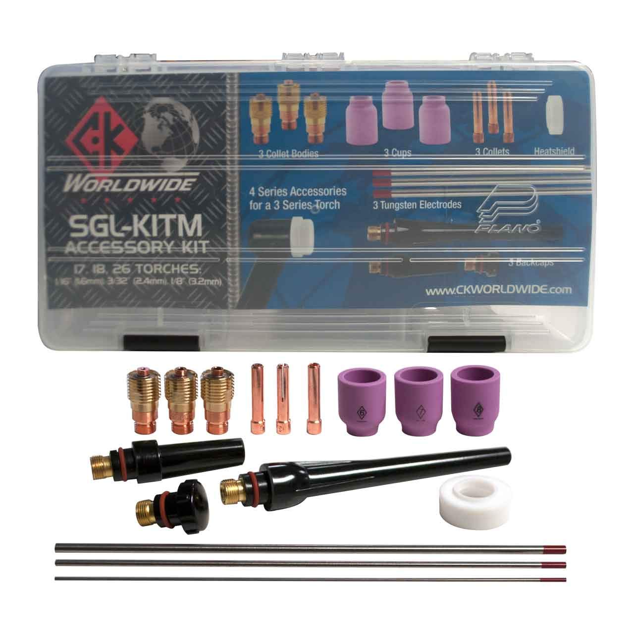
CK SGL-KITM TIG Accessory Kit, Stubby Gas Lens, 4GL, 1/16, 3/32, 1/8: Product Breakdown
“>
The CK SGL-KITM TIG accessory kit is a consumable set built around a stubby gas lens setup. For shops that run TIG work on thin material, tight access joints, or jobs that need better torch visibility, the main value is simple: it consolidates common gas lens and collet body sizes into one kit so the welder can match the torch setup to the tungsten and cup arrangement being used.
This breakdown focuses on what the kit is for, how to inspect it before use, and what to verify when the arc starts acting up. If you are buying for a welding bay, maintenance cart, or service truck, treat this as a consumable fit-check guide first and a product summary second.
Key Takeaways
- Stubby gas lens setups are used to improve access and visibility at the torch head.
- This kit includes three gas lens sizes identified as 4GL and three collet body sizes: 1/16, 3/32, and 1/8.
- Compatibility is listed for CK Worldwide TIG torches 17, 18, and 26.
- Actual fit should still be checked against the torch model, tungsten diameter, and cup setup before production use.
- Use Unknown (Verify) for any torch-specific dimension, thread detail, or application detail that is not confirmed by the source listing.
What the kit is intended to do
A gas lens helps smooth shielding gas flow at the torch end. In practical terms, that can improve shield coverage around the tungsten and weld puddle, especially when stickout increases or access is limited. A stubby arrangement shortens the front-end stack and can make the torch less bulky in confined positions. For welders, that usually means better line of sight and easier movement around corners, tube joints, and tight fillets.
Because this is a consumable accessory kit, the real value is in setup flexibility. The included 1/16, 3/32, and 1/8 sizes cover common tungsten diameters used in TIG work, but the operator still has to confirm that the torch body, collet body, cup, and tungsten all match the intended configuration. Do not assume every accessory in the kit is a universal fit.
Product and parts breakdown
Product: CK SGL-KITM TIG Accessory Kit, Stubby Gas Lens, 4GL, 1/16, 3/32, 1/8
Source listing: ArcWeld product page for CK Worldwide accessory kit
Listed compatibility: CK Worldwide TIG torches 17, 18, and 26
Included sizes: three gas lens sizes identified as 4GL, plus collet body sizes 1/16, 3/32, and 1/8
Material and finish: Unknown (Verify)
Country of origin: Unknown (Verify)
Thread or cup standards: Unknown (Verify)
When receiving the kit, sort the parts by size and confirm each piece is present. Shops should log the kit on the consumables shelf the same way they would log nozzles, collets, or back caps. That makes replenishment and cross-checking easier when a torch is down.
Inspection steps before first use
- Check packaging and count parts. Verify the number of gas lenses and collet bodies against the listing.
- Inspect the machined surfaces. Look for burrs, damaged threads, or bent components.
- Match tungsten diameter. Confirm the selected collet body matches the tungsten size being installed.
- Dry fit the stack. Assemble the torch front end without striking an arc to confirm parts seat correctly.
- Verify torch model fit. Confirm the torch is one of the listed CK Worldwide models, or mark the compatibility as Unknown (Verify) before proceeding.
Troubleshooting and support
If shielding coverage looks poor, do not immediately blame the power source. Front-end consumables are often the cause.
Check: Is the gas lens installed correctly and seated fully? Misalignment can disrupt gas flow.
Inspect: Look for clogged passages, damaged cup seating, or contamination on the tungsten and collet body.
Verify: Confirm gas flow rate, tungsten stickout, and cup setup are appropriate for the joint. Those values are application-dependent and should be set by procedure or shop standard. Unknown (Verify) if not documented.
If the tungsten keeps moving or the arc starts inconsistently, the issue may be mechanical rather than electrical.
Check: Is the correct collet body size installed for the tungsten diameter?
Inspect: Look for wear in the collet, damaged threads, or heat distortion.
Verify: The tungsten is straight, clean, and cut to the shop’s accepted prep standard.
If a torch feels too bulky for the joint, the stubby layout may help, but only if the rest of the setup is matched correctly.
Check: Cup size, tungsten length, and work angle.
Inspect: Clearance around the joint and whether the torch front end is contacting the part.
Verify: The job actually benefits from a shorter front-end arrangement. If not, use the standard consumable configuration approved for that weld.
Safety notes
- Do not install damaged consumables. Replace worn or cross-threaded parts before use.
- Let the torch cool before handling front-end parts after welding.
- Use appropriate eye, hand, and skin protection for TIG welding tasks.
- Keep shielding gas and cylinder handling in line with shop procedure.
- Do not guess at compatibility. If a torch model or size is not confirmed, mark it Unknown (Verify).
FAQ
Q: What is the main benefit of a stubby gas lens kit?
A: It can improve access and visibility at the torch head while supporting gas coverage at the tungsten. The practical benefit depends on the torch setup and job geometry.Q: Which torches does this kit fit?
A: The listing states CK Worldwide TIG torches 17, 18, and 26. If you are using a different torch, verify fit before purchase or installation.Q: Why are there three collet body sizes in one kit?
A: The 1/16, 3/32, and 1/8 sizes allow the user to match common tungsten diameters without swapping to a different consumable family.Q: Can this kit be used on all TIG welding jobs?
A: No. Use depends on torch model, tungsten size, cup setup, and weld access. Confirm the application requirements and verify the front-end configuration before production welding.Sources Checked
- ArcWeld product listing for CK SGL-KITM TIG Accessory Kit, Stubby Gas Lens, 4GL, 1/16, 3/32, 1/8
- Provided source idea text for listed compatibility and included sizes
Related Arc Weld Part
CK SGL-KITM TIG Accessory Kit, Stubby Gas Lens, 4GL, 1/16, 3/32, 1/8
Complete TIG torch accessory kit from CK Worldwide featuring stubby gas lens design for improved visibility and precision. Compatible with CK Worldwide TIG torches 17, 18, and 26. Includes three gas lens sizes (4GL) and three collet body sizes (1/16, 3/32, 1/8) for versatile tungsten electrode compatibility. Essential consumables for TIG welding on mild steel, stainless, and aluminum.
View at Arc Weld Store
CK20 TIG Torch Support: Parts Lookup and Buying Checks
CK20 TIG torch support starts with identification, then moves to parts verification. If the torch body, back cap, collet body, cup, or gas lens do not match the CK20 pattern, the wrong consumable set can create fit-up problems, gas coverage issues, or early wear. This guide is for buyers, welders, and maintenance teams who need a practical way to check what fits before ordering.
Key Takeaways
- Confirm the torch model and series before ordering any consumables.
- Check the torch breakdown against the support page, not memory or shop habit.
- Verify cup, collet, gas lens, and back cap style as a matched set where needed.
- Use Unknown (Verify) for any fitment detail that is not confirmed by the source page or your own machine records.
- Inspect wear parts for heat damage, thread wear, and loose fit before reuse.
What the WSP CK20 support page is for
The Weld Support Parts CK20 TIG Torch Support page is the starting point for machine and consumable lookup. The page is intended to help you find CK20 compatible machines, CK Series 2 consumables, gas lenses, cups, collets, and breakdown support. Use it as a reference point when you need to confirm what the torch uses or when you are matching replacement parts after a service call.
Open the lookup page here: CK20 TIG Torch Support.
Before you buy anything, compare the torch numberplate, handle markings, lead style, and consumable stack. If the torch is not clearly identified, treat compatibility as Unknown (Verify).
Check, inspect, verify: buying process
- Check the torch ID. Read the torch body, handle, and lead connection. If the marking is worn off, confirm from machine records or the service ticket.
- Inspect the current consumables. Remove the cup, collet, and back cap. Look for thread damage, cracked ceramic, burned O-rings, and discoloration from overheating.
- Verify the stack order. Gas lens, collet body, collet, and cup must match the torch setup. If any part is missing or substituted, record it before reordering.
- Match by function, not appearance. Two parts can look similar and still differ in thread form, length, or internal bore. If the source page does not confirm it, mark it Unknown (Verify).
- Cross-check replacement quantity. Buy enough for the active torch and a small service reserve. Do not assume all CK parts in stock are interchangeable without verification.
Troubleshooting support checks
If the torch is running poorly, use a basic check sequence before replacing parts.
Gas coverage problems
- Check: Is the cup cracked, blocked, or loose?
- Inspect: Look for soot, spatter, or heat damage on the gas lens and collet body.
- Verify: Confirm the cup size and gas lens style against the CK20 support reference. If not confirmed, Unknown (Verify).
Arc instability or wandering arc
- Check: Is the tungsten properly centered and secured?
- Inspect: Look for worn collet jaws, damaged collet body threads, or a bent tungsten stickout path.
- Verify: Confirm the torch is assembled with the correct CK Series 2 consumables if that is what the lookup page identifies for your setup.
Overheating at the front end
- Check: Is the duty cycle being exceeded for the application?
- Inspect: Look for darkened cups, soft back cap seals, and burned components near the nozzle end.
- Verify: Confirm the torch is actually the CK20 variant and not a similar torch with different duty limits or consumable geometry. Unknown (Verify) if not documented.
Parts and breakdown support workflow
Use the support page when a torch is already apart or when a replacement order is needed after failure. Start with the torch breakdown, then identify the wear parts in this order:
- Back cap
- Collet
- Collet body or gas lens body
- Cup or nozzle
- Insulators or seals, if used in that assembly
If a part is damaged beyond a visual ID, remove one confirmed sample from the line and match it directly. Do not order by description alone if the stack has been modified in the field. If a helper note, machine log, or purchase record does not confirm the part number, treat the replacement as Unknown (Verify).
What to inspect on used CK20 consumables
- Threads: Check for galling, cross-threading, and incomplete engagement.
- Ceramic cups: Inspect for chips, cracks, and heat checking.
- Collets: Look for jaw spread, oxidation, and poor tungsten grip.
- Gas lens screens: Check for clogging, distortion, or impact damage.
- Back caps: Verify seal condition and straightness.
If any item fails inspection, replace it as a set when needed. Mixing worn and new components can make the problem harder to diagnose.
Safety notes
- Shut down power and gas before disassembly.
- Allow the torch to cool before handling cups, collets, and gas lenses.
- Do not reuse parts with cracked ceramic, stripped threads, or heat-damaged seals.
- Use the correct PPE for hot work and sharp ceramic fragments.
- If machine compatibility is not confirmed, do not force-fit consumables. Mark it Unknown (Verify) and recheck the torch ID.
FAQ
How do I know if my torch is CK20 compatible?
Start with the torch marking, machine records, and the consumable stack already installed. Then compare it to the CK20 TIG Torch Support page. If the ID is unclear, treat compatibility as Unknown (Verify).
Can I mix CK consumables from different setups?
Not without verification. Some consumables may appear similar but differ in length, thread form, or internal geometry. Verify the exact stack before mixing parts.
What should I replace first if the torch has poor gas coverage?
Inspect the cup, gas lens, and collet body first. Check for cracks, clogging, and poor fit. Replace the damaged part and confirm the assembly order.
Where should I start when I need breakdown support?
Use the CK20 support page, then break the torch down into its consumable stack and compare each piece against a confirmed sample or documented machine record.
Sources Checked
- Weld Support Parts: CK20 TIG Torch Support
Any compatibility or fitment detail not directly confirmed from the source page or your shop records should be treated as Unknown (Verify).
Disclosure: As an Amazon Associate, Weld Support Parts may earn from qualifying purchases.
Gas Lens vs Standard Collet Body
Choosing between a gas lens and a standard collet body affects shielding gas coverage, tungsten access, and how the torch behaves around joints, corners, and root passes. The right choice depends on the weld joint, cup size, torch access, and how much arc stability you need. It is not a one-parts-fits-all decision.
This comparison covers practical differences, what to inspect when TIG shielding is inconsistent, and how to verify the torch setup before you blame the power source or the filler metal.
Key Takeaways
- A gas lens is used to straighten and distribute shielding gas more evenly at the cup outlet.
- A standard collet body is simpler and commonly used where access is open and gas coverage is already adequate.
- Gas lens setups are often chosen when the tungsten needs to stick out farther from the cup. Exact extension limits vary by setup and should be treated as Unknown (Verify).
- Standard collet bodies can be acceptable for basic joints, but shielding can be less forgiving if stickout, cup position, or gas flow is not controlled.
- If you see oxidation, gray tungsten, or erratic arc starts, inspect the torch consumables before changing machine settings.
Gas Lens vs Standard Collet Body: What Changes
A standard collet body holds the collet and tungsten in a direct flow path. It is a basic torch consumable and works in many general TIG applications. A gas lens adds a diffuser element that helps smooth the shielding gas stream before it exits the cup. That can improve coverage around the tungsten and weld puddle.
In practical terms, a gas lens is usually chosen when the torch needs better gas shielding at the work area, especially on open-root work, stainless, or places where the torch angle is awkward. A standard collet body can still weld cleanly when the cup is positioned properly and the gas flow is controlled. The tradeoff is less gas management margin.
Do not assume one is always better. The torch, cup size, tungsten size, gas flow rate, and joint access all affect results. If those variables are unknown, verify them before changing consumables.
When a Gas Lens Makes Sense
Use a gas lens when you need better shielding stability and more tolerance for tungsten extension. That usually matters on tight joints, inside corners, or when visibility requires a longer tungsten reach.
Check the following before switching:
- Is the cup size appropriate for the joint?
- Is the tungsten clean and properly sharpened?
- Is the gas path free of leaks, cracks, or missing parts?
- Is the flow meter set to a value that matches the setup? Exact flow is application dependent and may be Unknown (Verify).
Inspect the diffuser screen or internal gas distribution path for damage, spatter, dirt, or cross-threading. A damaged lens can create poor shielding and turbulence.
Verify that the cup, collet, and backcap parts match the torch system in use. The allowed WSP lookup page for this topic is the CK17 TIG Torch Support, which provides Series 3 breakdown routing. If you are matching a torch body or consumable family, confirm the actual torch model and consumable series before ordering.
When a Standard Collet Body Is Enough
A standard collet body is often enough for flat-position welds, open access joints, and routine TIG work where the tungsten stays close to the cup. It is also a simpler setup with fewer internal parts to inspect.
Check for these signs that the standard body is doing its job:
- The arc starts cleanly without wandering.
- The tungsten stays bright and free of visible contamination.
- The weld area does not show gray or sugary oxidation.
- Gas coverage remains stable through the full weld pass.
Inspect the collet body threads, collet seating, and cup fit. A loose cup or damaged threads can defeat both standard and gas lens setups.
Verify that the tungsten size, collet size, and cup style are correct for the torch. If those details are not documented, label them Unknown (Verify) and confirm against the actual torch assembly.
Troubleshooting Support: Symptoms and Checks
If weld quality drops, start with the consumables before adjusting the machine.
Symptom: Tungsten turns gray or contaminated
- Check whether the cup is cracked or loose.
- Inspect the tungsten for dip contact, oxidation, or a damaged point.
- Verify gas coverage at the joint before increasing amperage or changing filler.
Symptom: Arc feels unstable or wanders
- Check for a loose collet or poor tungsten clamp.
- Inspect the torch neck and consumable stack for misalignment.
- Verify that the tungsten protrusion is within the limits of the setup. Exact limits are Unknown (Verify).
Symptom: Shielding is weak at the edges of the puddle
- Check for drafts, fan air, or torch angle changes.
- Inspect the gas lens screen or collet body passages for blockage.
- Verify cup size and gas coverage against the joint geometry.
Practical Selection Guide
If the job gives you room and the weld is straightforward, start with the simpler setup that matches your existing torch parts. If the weld is more sensitive to shielding or requires longer tungsten extension, a gas lens is often the better test setup.
For maintenance buyers and support teams, the key is not to overbuy mixed parts without identifying the torch family first. Confirm the torch model, breakdown, and consumable series. The CK17 support page is the only provided WSP lookup reference for this topic, so use it as the routing point and verify the actual fit before purchase.
Safety Notes
- Turn off the power source before changing torch consumables.
- Let hot cups and tungsten cool before handling.
- Do not force threaded parts. Cross-threaded components can cause leaks and poor shielding.
- Use proper ventilation when TIG welding, especially on stainless, coated, or unknown base materials.
- Keep shielding gas cylinders secured and follow site gas handling procedures.
FAQ
Is a gas lens always better than a standard collet body?
No. A gas lens can improve gas coverage, but a standard collet body may be fully adequate for open access welds. The better choice depends on the joint, torch angle, and required tungsten extension.
Can I swap a gas lens into any TIG torch?
Not safely without verifying the torch model and consumable series. Compatibility is Unknown (Verify) unless the torch family and part series are confirmed through the actual breakdown or parts listing.
Why does my tungsten still oxidize with a gas lens?
Possible causes include a leak, loose cup, draft, contaminated tungsten, or incorrect setup. Inspect the full torch stack and verify gas coverage before changing to a different consumable style.
Should I change flow rate when switching from standard collet body to gas lens?
Maybe, but there is no universal setting. Flow depends on cup size, tungsten extension, joint access, and gas type. If the correct setting is not documented, mark it Unknown (Verify) and test methodically.
Sources Checked
- WSP CK17 TIG Torch Support
- Square Wave 205 TIG Gas Lens vs Standard Collet Body: When to Use Each Setup
Use the torch breakdown, confirm the consumable series, and verify the actual setup in the shop before standardizing one consumable style over the other.
Disclosure: As an Amazon Associate, Weld Support Parts may earn from qualifying purchases.
Related Weld Support Guides
Why TIG Arc Wanders or Starts Hard
Why TIG Arc Wanders or Starts Hard
If the tig arc wandering or a TIG arc starts hard, the cause is usually in one of four areas: work clamp contact, tungsten preparation, shielding gas coverage, or torch consumables. Start with the basics and verify each part of the current path and gas path before changing machine settings.
Key Takeaways
- Poor ground path can make arc starts unstable.
- Contaminated or poorly ground tungsten can cause arc wandering.
- Low gas flow, leaks, or draft can disturb shielding and arc stability.
- Damaged cups, collet bodies, or gas lenses can reduce shielding and control.
- Do not assume the torch is the problem until the work clamp and tungsten are verified.
Troubleshooting Steps
1) Check the work clamp and ground path
Make sure the work clamp is attached to clean metal with solid contact. Paint, rust, mill scale, oil, or loose clamp contact can interrupt current flow and make the arc hard to start or unstable once started.
- Move the clamp closer to the weld area if the current path is long.
- Inspect the clamp jaw, cable, and connector for heat damage or looseness.
- Verify the workpiece is clean where the clamp lands.
2) Inspect tungsten preparation
TIG arc wandering often starts with the tungsten. A dirty, blunt, uneven, or contaminated tungsten will not focus the arc well. Grind the tungsten lengthwise and keep the tip consistent with the process requirements for your material and amperage.
- Use a clean dedicated grinding wheel or method for tungsten only.
- Remove contamination if the tungsten touched filler, the puddle, or the cup.
- If the tip is balled, split, or uneven, replace or regrind it.
3) Verify shielding gas coverage
Gas issues can cause wandering starts, contamination, and erratic arc behavior. Check the cylinder flow, regulator, hose condition, torch seals, and cup coverage. Drafts in the work area can also break shielding gas coverage.
- Verify gas is actually flowing at the torch.
- Inspect hose connections and torch O-rings or seals, if equipped. Unknown (Verify).
- Reduce air movement from fans, doors, or shop draft near the weld.
- Confirm the gas type and flow rate are set for the job. Unknown (Verify).
4) Inspect torch consumables
Worn consumables can create inconsistent shielding and make arc starts less precise. Look at the cup, collet, collet body, and any gas lens components for cracks, buildup, or poor fit.
- Replace cracked or heat-damaged cups.
- Check for contamination inside the torch head.
- Verify the consumables match the torch and tungsten size used. Unknown (Verify) if not confirmed by the torch model.
5) Check start settings and process setup
If the basics are correct, review start settings. Too little or too much start current, improper HF start behavior, or incorrect post-flow can affect arc initiation and stability. Exact settings depend on the machine and process. Unknown (Verify).
- Confirm the machine is set for the intended TIG process.
- Check foot pedal, torch switch, or remote input function.
- Verify the tungsten size is appropriate for the current range. Unknown (Verify).
When the Arc Wanders During the Weld
If the arc starts correctly but wanders during travel, look for heat buildup, tungsten contamination, arc length changes, or shielding disruption from torch angle and stickout.
- Keep tungsten stickout consistent.
- Hold a stable torch angle.
- Do not extend the tungsten farther than needed for access.
- Recheck gas coverage if the weld area is tight or recessed.
Product and Parts
When consumables are worn or the torch needs a cleaner gas shield, a stubby gas lens kit can help improve visibility and access on compatible torches. Product compatibility below is provided only as listed.
CK SGL-KITM TIG Accessory Kit, Stubby Gas Lens, 4GL, 1/16, 3/32, 1/8
Short description: Complete TIG torch accessory kit from CK Worldwide featuring stubby gas lens design for improved visibility and precision. Compatible with CK Worldwide TIG torches 17, 18, and 26. Includes three gas lens sizes (4GL) and three collet body sizes (1/16, 3/32, 1/8) for versatile tungsten electrode compatibility. Essential consumables for TIG welding on mild steel, stainless, and aluminum.
Use the listed product only where it matches the torch and tungsten setup. If torch model or consumable size is not confirmed, verify before ordering.
CK SGL-KITM TIG Accessory Kit, Stubby Gas Lens, 4GL, 1/16, 3/32, 1/8
Complete TIG torch accessory kit from CK Worldwide featuring stubby gas lens design for improved visibility and precision. Compatible with CK Worldwide TIG torches 17, 18, and 26. Includes three gas lens sizes (4GL) and three collet body sizes (1/16, 3/32, 1/8) for versatile tungsten electrode compatibility. Essential consumables for TIG welding on mild steel, stainless, and aluminum.
View at Arc Weld StoreSafety Notes
- Shut power off before changing consumables or touching internal torch parts.
- Allow hot tungsten and cups to cool before handling.
- Do not grind tungsten in a way that contaminates the shop or exposes hands and eyes to dust.
- Use local exhaust ventilation when welding and when grinding tungsten.
- Do not weld with damaged leads, cracked torch parts, or leaking gas equipment.
FAQ
Why does TIG arc wandering happen right at start?
The most common causes are poor ground contact, contaminated tungsten, or weak shielding gas coverage.
Can a bad work clamp cause hard starts?
Yes. A poor clamp connection can interrupt the current path and make arc initiation unreliable.
Does tungsten shape matter?
Yes. An uneven or contaminated tungsten can make the arc unstable and harder to direct.
Can airflow affect TIG starts?
Yes. Draft can disturb shielding gas and cause unstable starts or contamination.
Sources Checked
- Provided ArcWeld product data for CK SGL-KITM TIG Accessory Kit
- Topic brief: troubleshoot arc starts, grounding, tungsten prep, and shielding gas issues
TIG Torch Gas Leak Troubleshooting: Argon Loss, Black Tungsten, Porosity, and Torch Seal Checks
If a TIG torch has a gas leak, the weld may show black tungsten, gray weld color, porosity, sugaring on stainless, unstable starts, or a loud uneven gas hiss even when the regulator shows normal flow. Start at the cylinder and work forward to the cup. A TIG gas leak can be at the regulator, machine inlet, solenoid, torch hose, power cable/gas hose, torch head, collet body, gas lens, cup seal, back cap O-ring, or torch valve.
The fast check is to verify 100% argon, confirm flow at the torch with a flow tester, inspect the cup/gas lens/collet body/back cap, then leak-test fittings with approved leak-check solution. Do not raise flow to hide a leak. Too much flow can pull air into the shielding envelope and make the weld dirtier. For related TIG shielding symptoms, see TIG shielding gas coverage troubleshooting, why TIG tungsten turns black, and TIG welds looking sooty.
Common Symptoms
- Tungsten turns black, blue, gray, or chalky after welding.
- Weld bead has porosity, soot, oxidation, or gray color.
- Stainless shows sugaring, crusting, or dark heat tint near the root.
- Arc starts unstable even with clean tungsten.
- Gas hiss sounds loud, weak, pulsed, or uneven at the cup.
- Regulator flow reads normal, but flow at the cup is low.
- Shielding improves when the torch hose is moved or held straight.
- Back cap area hisses during post-flow.
- Gas flow stops too early and tungsten discolors after arc-off.
Likely Causes
| Cause | What It Does | Quick Check |
|---|---|---|
| Loose regulator or hose fitting | Leaks argon before it reaches the machine or torch | Leak-check fittings with solution |
| Cracked TIG gas hose | Pulls air or loses shielding gas before the cup | Flex hose during post-flow and check for bubbles |
| Loose collet body or gas lens | Leaks inside the torch head or disrupts flow | Remove cup and verify body is seated tight |
| Damaged back cap O-ring | Leaks around the rear of the torch head | Inspect O-ring for cuts, flattening, heat damage, or missing seal |
| Cracked cup or wrong insulator | Breaks the gas seal and creates turbulence | Replace cup and confirm correct gasket/insulator stack |
| Plugged gas lens screen | Restricts or distorts argon flow | Hold lens to light and inspect screen |
| Bad torch valve | Leaks or fails to shut off on valve-style torches | Close valve and check if gas continues |
| Short post-flow | Lets hot tungsten oxidize after welding | Increase post-flow and hold torch over weld |
Fast Diagnosis Sequence
- Confirm the cylinder is 100% argon for normal TIG work unless the procedure calls for another approved shielding gas.
- Check the regulator, flowmeter, and cylinder connection.
- Confirm gas flow at the torch cup, not only at the regulator.
- Inspect the cup for cracks, chips, heat damage, wrong size, or poor seating.
- Remove and inspect the collet body or gas lens. It must seat fully in the torch head.
- Inspect the back cap O-ring and back cap threads.
- Check torch hose, power cable/gas hose, machine inlet, and torch valve for leaks.
- Use leak-check solution on fittings. Do not use flame.
- Reduce excessive flow if the gas sounds like a hard blast instead of a smooth shield.
- Retest with clean tungsten, normal stickout, and no drafts.
Inspection Steps
- Regulator and flowmeter: Confirm proper connection, stable flow reading, no damaged CGA fitting, and no cracked hose barb.
- Machine gas inlet/outlet: Inspect loose fittings, cracked internal hose, and gas solenoid area only with power disconnected.
- Torch hose: Look for cuts, burned sections, kinks, loose crimps, or leaks that appear only when the hose is flexed.
- Torch head: Inspect threads, heat damage, loose head-to-body connection, and valve packing on valve torches.
- Collet body/gas lens: Verify it is the correct type for the torch series and cup system. A loose or mismatched body can leak or disturb gas flow.
- Back cap: Check O-ring, cap length, threads, and whether the tungsten is clamped without bottoming the cap incorrectly.
- Cup and insulator: Confirm the cup is not cracked and the correct gasket/insulator is installed for standard or gas-lens setup.
- Post-flow: Gas must continue long enough to shield the hot tungsten and cooling weld area.
Test Procedures
- Cup flow test: Use a TIG flow tester at the cup. A regulator reading alone does not prove flow at the torch.
- Bubble leak test: Apply approved leak-check solution to fittings during flow or post-flow. Bubbles identify leakage.
- Hose flex test: Run post-flow and gently flex the hose. If flow or bubbles change, replace damaged hose or cable assembly.
- Back cap test: Listen and check around the back cap during post-flow. Replace damaged O-rings and verify correct cap.
- Front-end swap test: Install a known-good cup, collet body/gas lens, collet, back cap, and insulator. If shielding improves, the leak or turbulence was in the torch front end.
- Post-flow test: Hold the torch still after arc-off. If the tungsten stays bright after increasing post-flow, the issue was hot tungsten oxidation.
Root Cause Analysis
TIG shielding must protect the tungsten, arc, filler rod end, and weld puddle from oxygen and nitrogen. A leak before the torch wastes argon and can lower flow at the cup. A leak or bad seal inside the torch head can mix air into the shielding zone. A damaged gas lens or cracked cup can create turbulence even when flow volume looks correct.
Gas leaks are often mistaken for bad tungsten or dirty filler. The tungsten turns black, the weld gets sooty, and the operator increases gas flow. If the actual problem is a cracked cup, missing O-ring, loose gas lens, or leaking hose, more gas may make turbulence worse. Correct the seal and gas path first, then tune cup size, flow, torch angle, and stickout.
Compatibility Notes
Do not order TIG torch gas parts by cup size alone. Verify torch series, cooling type, torch head style, collet size, collet body style, gas lens style, cup thread or push-on style, back cap length, O-ring, gasket/insulator, power connector, gas connector, and machine connection. Common 9/20 and 17/18/26-style parts are not automatically interchangeable.
Gas-lens conversions also require the correct insulator, cup, collet body, collet, and sealing ring where used. Mixing standard collet bodies with gas-lens cups, or using the wrong insulator stack, can create leaks at the torch head. If the torch model or consumable system is not confirmed, mark the part as Unknown (Verify).
What To Verify Before Ordering
- TIG torch series: 9, 17, 18, 20, 26, or manufacturer-specific equivalent.
- Air-cooled or water-cooled torch.
- Valve torch or machine-solenoid torch.
- One-piece or two-piece cable/hose arrangement.
- Back cap length and O-ring style.
- Collet size matching tungsten diameter.
- Standard collet body or gas lens collet body.
- Cup style, cup size, insulator/gasket, and sealing ring.
- Machine gas connector, quick connector, or separate gas hose fitting.
- Argon regulator/flowmeter outlet fitting and hose size.
Common Wrong-Part Mistakes
- Installing a gas-lens cup without the correct gas-lens body and insulator.
- Using a 17/18/26 front-end kit on a 9/20 torch.
- Replacing tungsten repeatedly while leaving a cracked cup in service.
- Using a back cap with a missing, cut, or flattened O-ring.
- Over-tightening ceramic cups until they crack.
- Using a MIG flowmeter or wrong-pressure flow device on a TIG torch setup.
- Raising argon flow too high and creating turbulence instead of fixing the leak.
Field Fix vs Proper Fix
| Problem | Field Fix | Proper Fix |
|---|---|---|
| Back cap leak | Reseat cap and reduce movement | Replace O-ring or correct back cap |
| Cracked cup | Install spare cup | Verify correct cup, insulator, and torch angle/stickout |
| Loose gas lens | Snug gas lens body | Replace damaged gas lens, filter, seal, or torch threads |
| Leaking hose | Stop using the torch | Replace hose, cable assembly, or torch |
| Black tungsten after arc-off | Add post-flow | Correct post-flow, leaks, drafts, and cup coverage |
Related Failure Paths
- Black tungsten: Hot tungsten is exposed to oxygen from poor shielding, leaks, or short post-flow.
- Porosity: Air enters the weld puddle through a leak, draft, bad cup seal, or contaminated gas path.
- Arc instability: Gas turbulence and tungsten oxidation make starts and arc focus inconsistent.
- Sugaring on stainless: Shielding loss at the puddle or root side allows heavy oxidation.
- Short consumable life: Leaks and overheating damage cups, collets, gas lenses, and O-rings.
Safety Notes
- Close the cylinder valve and bleed pressure before removing gas fittings.
- Disconnect input power before opening machine covers or checking internal gas hoses.
- Use approved leak-check solution. Never use flame to find gas leaks.
- Argon can displace oxygen in confined spaces. Maintain ventilation.
- Do not weld with cracked torch hoses, burned cables, or leaking torch heads.
- Hot cups and torch heads can burn skin and gloves; allow cooling before disassembly.
- Use correct PPE and follow the torch and machine manual for service limits.
Sources Checked
Sources checked include TIG torch parts catalog data, TIG shielding gas flow references, torch manual troubleshooting notes, and related Weld Support Parts TIG shielding articles. Final replacement must be verified by torch series, cable/hose style, back cap/O-ring, cup system, collet body or gas lens type, tungsten diameter, machine connection, and shielding gas setup.
TIG Arc Starting Problems and Fixes: Hard Starts, Arc Wander, HF Start Failure, and Contaminated Tungsten
TIG arc starting problems usually come from tungsten condition, work clamp contact, gas coverage, torch setup, or start-mode settings before they come from a failed machine. If the arc will not start, starts only when scratched, wanders at ignition, snaps to the cup, or contaminates the tungsten immediately, check the tungsten point, work lead, cup/gas lens, collet grip, polarity, amperage start setting, and HF or lift-arc mode first.
The fastest check is to install a clean sharpened tungsten, clamp directly to clean bare metal, verify argon at the cup, remove drafts, and try a start on clean scrap. If the arc starts normally after those steps, the problem was setup or consumable condition, not the power source.
Related TIG checks include unstable TIG arc from poor tungsten prep, why TIG tungsten turns black, TIG porosity troubleshooting, and TIG cup size and gas coverage selection.
Common Symptoms
| Symptom | Likely Cause | First Check |
|---|---|---|
| Arc will not start with HF | Wrong mode, poor work lead, dirty tungsten, HF issue | Confirm HF start mode and clamp to clean metal |
| Arc starts only by touching | HF not active or work path too weak | Verify start mode, pedal/remote, and work clamp |
| Arc wanders at start | Poor tungsten grind, contaminated tungsten, long arc length | Regrind tungsten and shorten arc gap |
| Tungsten sticks on lift start | Too much pressure or wrong lift technique | Touch lightly and lift smoothly |
| Arc jumps to cup or side of tungsten | Loose collet, cracked cup, dirty gas lens, off-center tungsten | Inspect torch front end |
| Starts rough after every stop | Too little post-flow or contaminated tungsten | Check tungsten color and post-flow time |
Most Common Causes
- Contaminated tungsten: touching the filler, puddle, bench, or dirty base metal makes starts rough.
- Poor tungsten prep: uneven grind marks, blunt tips, split tips, and wrong taper make the arc wander.
- Weak work clamp path: paint, rust, mill scale, loose lugs, or clamping through a table can block a clean start.
- Wrong start mode: HF, lift-arc, scratch start, 2T/4T, pedal, or remote settings may not match the torch setup.
- Gas coverage failure: bad cup, clogged gas lens, loose back cap, low post-flow, or drafts oxidize the tungsten.
- Wrong tungsten size for amperage: oversized tungsten can be hard to start at very low amperage; undersized tungsten overheats.
- Dirty base metal: aluminum oxide, oil, rust, and coatings interfere with stable starts.
Inspection Steps
- Confirm process and polarity. Most DC TIG on steel/stainless uses DCEN. AC is used for aluminum and magnesium on AC-capable machines.
- Confirm start mode. Know whether the machine is set for HF start, lift-arc, or scratch start.
- Regrind tungsten. Use a clean dedicated wheel or tungsten grinder. Grind lengthwise, not around the electrode.
- Check tungsten size. Match electrode diameter to amperage range and machine start capability.
- Clamp directly to the work. Clean to bare metal and avoid relying on rusty tables, hinges, or fixtures.
- Inspect the torch front end. Check cup, gas lens, collet, collet body, back cap, O-ring, and tungsten centering.
- Verify argon at the cup. Flow at the regulator does not prove gas is reaching the tungsten.
- Check post-flow. If tungsten turns blue, gray, or black after the stop, it may start poorly next time.
- Try clean scrap. If the arc starts clean on scrap, the original part may be dirty, coated, oxidized, or poorly grounded.
HF Start vs Lift-Arc Checks
| Start Type | Problem | Fix |
|---|---|---|
| HF start | No arc unless touching | Confirm HF mode, remote settings, work clamp, and torch connection |
| HF start | Arc wanders before stabilizing | Regrind tungsten, shorten arc gap, clean base metal |
| Lift-arc | Tungsten sticks | Use lighter touch and smoother lift; clean tungsten and workpiece |
| Scratch start | Tungsten contamination | Use a copper strike plate or HF/lift start where procedure allows |
| Any mode | Hard restart | Increase post-flow, regrind tungsten, inspect gas leaks |
Field Fix vs Proper Fix
| Problem | Field Fix | Proper Fix |
|---|---|---|
| Dirty tungsten | Regrind point | Fix dipping, filler angle, gas coverage, and post-flow |
| Weak work path | Move clamp to clean metal | Repair cable, lug, clamp, or table return path |
| Arc wanders | Shorten arc length | Correct tungsten grind, size, and torch angle |
| Lift start sticks | Touch lighter | Confirm lift mode and clean contact point |
| HF start fails repeatedly | Try lift mode if available | Have HF circuit/service items checked by qualified repair |
Common Wrong-Part Mistakes
- Using a collet that does not match tungsten diameter.
- Installing a gas lens without the matching cup and insulator setup.
- Buying torch parts by welder model instead of torch series.
- Using oversized tungsten for low-amp work and blaming the machine for hard starts.
- Replacing the foot pedal before checking torch switch, remote setting, work clamp, and tungsten condition.
Compatibility Notes
TIG start behavior depends on welder start type, torch switch or pedal setup, tungsten size, torch family, collet size, gas lens or standard collet body, cup size, and work lead condition. WP-9/20-style consumables and WP-17/18/26-style consumables are not automatically interchangeable. Verify torch series and tungsten diameter before ordering consumables.
Related Failure Paths
- Black tungsten from low post-flow or gas leaks.
- Arc wander from poor tungsten preparation.
- Porosity from poor gas coverage during start and stop.
- Tungsten inclusion from scratch starting or sticking lift starts.
- Hard starts from poor work clamp contact.
- Unstable starts from dirty aluminum oxide or contaminated base metal.
Safety Notes
- Disconnect input power before servicing torch leads, work leads, or internal machine connections.
- Use eye protection when grinding tungsten.
- Follow shop rules for thoriated tungsten handling and dust control.
- High-frequency start can interfere with sensitive electronics; follow equipment and site requirements.
- Secure argon cylinders and use ventilation during test welds.
Sources Checked
- Weld Support Parts tungsten prep, tungsten discoloration, TIG porosity, and TIG cup support pages.
- CK Worldwide TIG guide and TIG troubleshooting guidance.
- Miller TIG welding basics and TIG problem troubleshooting guidance.
- Lincoln Electric high-frequency TIG start technology reference.
TIG Post-Flow Setting Troubleshooting: Black Tungsten, Porosity, Gas Waste, and Torch Cooling
TIG post-flow is the shielding gas that keeps flowing after the arc stops. If it is too short, the hot tungsten and cooling weld crater are exposed to air, causing black, blue, gray, or crusty tungsten, rough restarts, porosity, and contaminated weld starts. If post-flow is too long, weld quality may be fine, but argon usage goes up fast during tack welding or short beads.
Start by watching the tungsten after arc stop. If the tungsten is still glowing when argon shuts off, increase post-flow. If the tungsten stays clean but gas keeps flowing long after the torch cools, reduce post-flow in small steps. Do not fix black tungsten by only increasing flow rate; a cracked cup, leaking back cap O-ring, clogged gas lens, or loose torch fitting can still expose the electrode to oxygen.
Related TIG checks include why TIG tungsten turns black, TIG porosity troubleshooting, sooty TIG weld gas coverage fixes, and TIG cup size and gas lens selection.
Common Symptoms
| Symptom | Likely Post-Flow Issue | First Check |
|---|---|---|
| Tungsten turns black after weld | Post-flow too short or gas leak | Increase post-flow and inspect gas path |
| Tungsten turns blue or gray | Hot tungsten exposed during cooling | Watch whether gas stops before glow is gone |
| Rough arc restart | Oxidized tungsten from previous stop | Regrind tungsten and extend post-flow |
| Porosity at crater or restart | Weld pool loses shielding while cooling | Hold torch over crater during post-flow |
| Argon bottle empties quickly | Post-flow too long for short welds | Reduce time gradually after tungsten stays clean |
What Post-Flow Does
Post-flow protects three hot areas after the arc shuts off: the tungsten, the weld crater, and the end of the filler rod if it remains inside the gas envelope. Tungsten can oxidize after the bead looks finished because the electrode remains hot longer than many operators expect. The goal is enough shielding to let the tungsten cool without discoloration, not maximum gas flow for every weld.
Starting Point for Post-Flow
A common field rule is about 1 second of post-flow per 10 amps of welding current. Some Miller GTAW guidance also lists 10–15 seconds as a corrective range when inadequate post-flow is causing tungsten or arc problems. Use those as starting points, then tune by tungsten color, material, torch heat, tungsten size, and weld length.
| Welding Current | Common Starting Range | What To Watch |
|---|---|---|
| 50 amps | 5 seconds | Tungsten should not color after gas stops |
| 80 amps | 8 seconds | Good range for many light TIG jobs |
| 120 amps | 12 seconds | Check torch heat and tungsten color |
| 150 amps | 15 seconds | Often needs longer protection on hot torch setups |
| 200 amps | 20 seconds | Verify torch rating and cooling; gas use increases quickly |
Inspection Steps
- Confirm the gas. Most TIG work uses 100% argon. Do not use MIG gas with CO2 or oxygen for TIG.
- Watch tungsten color. Black, gray, blue, or crusted tungsten after arc stop points to oxygen exposure, contamination, or too little post-flow.
- Hold the torch still. Keep the cup over the crater until post-flow ends. Moving away early defeats the setting.
- Check flow at the cup. A regulator reading does not prove gas is reaching the tungsten.
- Inspect the cup. Replace cracked, chipped, loose, or overheated cups.
- Inspect the gas lens or collet body. Blocked screens or damaged gas passages can cause poor coverage even with long post-flow.
- Check the back cap O-ring. A damaged O-ring can pull air into the torch and oxidize tungsten.
- Check hoses and fittings. Use approved leak-check methods and repair leaks before welding.
- Adjust gradually. Add or subtract a few seconds at a time, then retest on clean material.
Post-Flow Too Short vs Too Long
| Condition | Result | Corrective Action |
|---|---|---|
| Too short | Black tungsten, rough restarts, crater oxidation | Increase time and hold torch over weld |
| Too long | High argon consumption with no quality gain | Reduce time after tungsten remains clean |
| Correct time but black tungsten | Leak, cracked cup, bad O-ring, dirty gas lens | Inspect torch and gas path |
| Correct time but porosity | Draft, contamination, wrong cup, no purge | Check shielding coverage and base-metal prep |
Field Fix vs Proper Fix
| Problem | Field Fix | Proper Fix |
|---|---|---|
| Tungsten blackens after stop | Add post-flow time | Set time by amps and repair leaks or worn torch parts |
| Gas wastes during tacks | Lower post-flow slightly | Use a repeatable tack schedule that still protects tungsten |
| Crater porosity | Hold torch over crater longer | Correct post-flow, torch angle, cup size, and cleanliness |
| Blue tungsten on aluminum | Add post-flow | Check AC heat, torch cooling, gas lens, and cup size |
| Soot remains after increasing post-flow | Clean cup and tungsten | Fix gas coverage, contaminated material, or wrong gas |
Common Wrong-Part Mistakes
- Replacing tungsten repeatedly while ignoring a leaking back cap O-ring.
- Using a cracked cup and trying to compensate with longer post-flow.
- Installing gas lens parts that do not match the torch series or cup setup.
- Using a collet that does not match tungsten diameter, causing poor alignment and overheating.
- Turning gas flow too high and creating turbulence instead of fixing post-flow time.
Compatibility Notes
Post-flow is a machine setting, but the correct result depends on torch family, cup size, gas lens or standard collet body, tungsten diameter, amperage, material, and torch cooling. Consumables for WP-9/20-style torches and WP-17/18/26-style torches are not automatically interchangeable. Verify torch series and tungsten diameter before replacing cups, collets, gas lenses, or back caps.
Related Failure Paths
- Black tungsten from oxygen exposure after arc stop.
- Rough arc starts from oxidized tungsten.
- TIG porosity at crater or restart.
- Sooty TIG welds caused by poor gas coverage.
- Cracked cups or clogged gas lenses mistaken for bad post-flow.
- High argon use from excessive post-flow during tack welding.
Safety Notes
- Let tungsten, cups, and torch parts cool before handling.
- Secure argon cylinders upright and protect regulators from impact.
- Argon can displace oxygen in confined areas; use ventilation and confined-space controls where required.
- Use eye protection when grinding tungsten.
- Do not weld through suspected gas leaks or damaged hoses.
Sources Checked
- Weld Support Parts TIG tungsten discoloration support page.
- Weld Support Parts TIG porosity and soot troubleshooting pages.
- Weld Support Parts TIG cup size and gas lens support page.
- CK Worldwide TIG troubleshooting and gas shielding guidance.
- Miller GTAW troubleshooting guidance.
TIG Torch Consumable Wear Signs: Cup Cracks, Collet Slip, Gas Lens Clogs, and Dirty Tungsten
Worn TIG torch consumables usually show up as dirty tungsten, rough arc starts, porosity, black soot, poor gas coverage, tungsten slipping, cup cracking, and inconsistent bead color. The problem is often not the welder. It is usually in the torch front end: cup, collet, collet body, gas lens, back cap, O-ring, insulator, or tungsten.
Start by checking the parts that control gas flow and tungsten grip. A cracked cup leaks shielding gas. A worn collet lets the tungsten slide or sit off-center. A clogged gas lens disrupts argon flow. A damaged back cap O-ring can pull air into the torch. If the tungsten turns black, the weld gets sooty, or the arc wanders after consumables heat up, inspect the torch before changing amperage or blaming the machine.
Related TIG support checks include why TIG tungsten turns black, TIG porosity troubleshooting, TIG cup size selection, and sooty TIG weld gas coverage fixes.
Common Symptoms
| Symptom | Likely Worn Consumable | First Check |
|---|---|---|
| Tungsten slips or pulls back | Collet, collet body, back cap | Inspect collet grip and correct tungsten size |
| Black or gray tungsten | Cup, gas lens, O-ring, gas leak | Verify argon flow and post-flow |
| Porosity appears suddenly | Cracked cup, clogged gas lens, leaking torch | Inspect cup and gas lens screen |
| Arc wanders | Contaminated tungsten, loose collet, worn collet body | Regrind tungsten and check clamp force |
| Soot around weld | Poor gas coverage, damaged cup, turbulent flow | Check cup size, gas lens, and torch angle |
| Cup keeps cracking | Overheating, impact, wrong cup setup | Check amperage, cup fit, and torch cooling |
What Each TIG Consumable Does
- Cup/nozzle: directs shielding gas around the tungsten and weld pool.
- Collet: grips the tungsten when the back cap is tightened.
- Collet body: holds the collet and positions the tungsten in the torch.
- Gas lens: smooths gas flow and improves coverage, especially with longer stickout.
- Back cap: tightens the collet and seals the rear of the torch.
- O-rings and insulators: prevent gas leaks and keep torch parts sealed and aligned.
- Tungsten: carries the arc; contamination or overheating changes arc shape immediately.
Visual Wear Indicators
| Part | Wear Signs | Replace When |
|---|---|---|
| Cup | Cracks, chips, white/brown heat marks, spatter, metal dust | Cracked, leaking, loose, or no longer shielding evenly |
| Collet | Split end spread open, burn marks, weak grip, oval bore | Tungsten slips or will not center |
| Collet body | Damaged threads, poor seating, discoloration, loose fit | Collet will not tighten or tungsten sits crooked |
| Gas lens | Clogged screen, dark deposits, crushed mesh, blocked holes | Gas flow becomes uneven or soot/porosity continues |
| Back cap | Cracked body, damaged threads, missing or flat O-ring | Gas leaks or tungsten will not clamp correctly |
| Insulator/gasket | Burned edges, cracks, missing seal, loose cup fit | Cup leaks, torch heats unevenly, or gas coverage fails |
Inspection Steps
- Let the torch cool. Ceramic cups, tungsten, and copper parts can stay hot after short welds.
- Remove the cup. Check for cracks, chips, dirt, and signs of gas leakage.
- Remove the tungsten. If it is black, crusted, split, balled unexpectedly, or contaminated, regrind or replace it.
- Inspect the collet. Match it to the tungsten diameter. Replace it if grip is weak or the split end is distorted.
- Inspect the collet body or gas lens. Look for blocked screens, damaged threads, and heat discoloration.
- Check the back cap and O-ring. A damaged seal can cause gas coverage problems that look like bad argon.
- Reassemble with matching parts. Do not mix standard cups with gas lens hardware unless the setup is designed for it.
- Test gas flow at the cup. Confirm steady argon flow before striking an arc.
- Run one test bead. Keep amperage and travel unchanged so the consumable change is the isolated variable.
Test Procedures
Tungsten grip test: Install the correct tungsten and tighten the back cap normally. If the tungsten slides with light hand pressure, inspect the collet, collet body, and back cap threads.
Gas coverage test: Weld a short bead with clean tungsten, clean base metal, and no drafts. If bead color improves after replacing the cup or gas lens, the old consumable was disturbing gas flow.
Post-flow test: Watch the tungsten after arc stop. If it turns blue, gray, or black quickly, check post-flow, back cap seal, cup damage, gas lens blockage, and hose leaks.
Field Fix vs Proper Fix
| Problem | Field Fix | Proper Fix |
|---|---|---|
| Tungsten slipping | Tighten back cap slightly | Replace worn collet and verify tungsten diameter |
| Dirty gas lens | Brush or blow out lightly | Replace clogged or damaged screen assembly |
| Cracked cup | Swap cup immediately | Match cup type to torch, amperage, and joint access |
| Black tungsten | Increase post-flow | Repair leaks and replace bad cup, O-ring, or gas lens |
| Arc wanders | Regrind tungsten | Fix collet grip, tungsten contamination, and gas coverage |
Common Wrong-Part Mistakes
- Buying TIG cups by size number only without confirming torch series.
- Using a 17/18/26 collet on a 9/20-style torch or the reverse.
- Installing a gas lens without the matching cup and insulator setup.
- Using a collet that does not match tungsten diameter.
- Replacing tungsten repeatedly while ignoring a leaking back cap O-ring.
- Running long tungsten stickout with a standard collet body when gas lens coverage is needed.
Compatibility Notes
TIG consumables must match the torch family, tungsten diameter, cup style, gas lens or standard collet body setup, and back cap style. Common 17/18/26-style consumables are larger than 9/20-style consumables and should not be treated as interchangeable. If the torch has been replaced in the field, do not order consumables by welder model alone.
Related Failure Paths
- TIG porosity from cracked cups, poor gas lens flow, or leaking O-rings.
- Dirty tungsten from insufficient post-flow or gas leakage.
- Arc wander from weak collet grip or contaminated tungsten.
- Black soot from turbulent argon flow or damaged front-end parts.
- Cup overheating from excess amperage, wrong cup setup, or poor torch cooling.
Safety Notes
- Let hot torch parts cool before disassembly.
- Use eye protection when grinding tungsten or cleaning cups.
- Disconnect power before deeper torch or machine service.
- Secure argon cylinders and use ventilation during test welds.
- Follow shop procedures for thoriated tungsten handling and grinding dust control.
Sources Checked
- Weld Support Parts TIG cup, gas lens, tungsten discoloration, and porosity support pages.
- ESAB/TBi TIG torch consumable guidance.
- Grainger TIG gas lens and collet body descriptions.
- Weldmonger TIG torch consumables overview.
TIG Shielding Gas Coverage Troubleshooting: Porosity, Soot, Tungsten Color, and Cup Setup
Poor TIG shielding gas coverage shows up as porosity, gray or black weld color, dirty tungsten, unstable arc starts, sugaring on stainless, and oxidation around the bead. The most common causes are low argon flow, excessive flow creating turbulence, torch angle pulling air into the puddle, drafts, a cracked cup, damaged gas lens, loose torch parts, gas leaks, or not enough post-flow after the weld.
Start with the gas path before changing amperage. Confirm 100% argon for most TIG work, verify flow at the torch, remove drafts, inspect the cup and gas lens, shorten tungsten stickout, and hold a tighter torch angle. If tungsten stays bright and the weld color improves after these checks, the problem was coverage—not the machine.
Related TIG support checks include TIG porosity troubleshooting, sooty TIG weld gas coverage fixes, and TIG cup size selection.
Common Symptoms
| Symptom | Likely Coverage Cause | First Check |
|---|---|---|
| Pinholes or porosity | Air entering weld zone or contaminated gas path | Verify argon flow at torch and check leaks |
| Black soot on weld | Weak shielding, torch angle, dirty lens, draft | Inspect cup/lens and block air movement |
| Tungsten turns blue, black, or crusty | Hot tungsten exposed after arc stops | Increase post-flow and check torch angle |
| Stainless weld turns dark gray | Insufficient argon envelope or no back purge | Check cup size, gas lens, and backside shielding |
| Arc wanders or starts rough | Contaminated tungsten or loose collet parts | Regrind tungsten and inspect collet/collet body |
What Shielding Gas Coverage Does
TIG shielding gas protects the tungsten, arc column, molten weld pool, and hot cooling metal from oxygen and nitrogen. When coverage breaks down, the puddle oxidizes before it solidifies. On stainless and titanium, poor shielding can damage corrosion resistance and weld quality. On carbon steel and aluminum, it can leave porosity, soot, rough starts, and contaminated tungsten.
Inspection Steps
- Confirm the gas. Most TIG welding uses 100% argon. Unknown mixed gas is a common mistake when switching between MIG and TIG.
- Verify flow at the torch. Do not rely only on the regulator. A kinked hose, loose fitting, blocked torch, or bad connector can reduce actual flow.
- Start in the normal TIG range. Many shop setups start around 15–20 CFH. Larger cups, aluminum, or longer stickout may need more, but excessive flow can pull air into the shield.
- Block drafts. Fans, open doors, outdoor work, and fume extraction too close to the arc can strip argon away.
- Inspect the cup. Replace chipped, cracked, contaminated, or oversized/undersized cups that do not match the joint.
- Inspect the gas lens or collet body. Look for plugged screens, cracks, discoloration, or damaged threads.
- Check tungsten stickout. Too much stickout without a gas lens exposes the tungsten and puddle to air.
- Correct torch angle. Keep the torch close to vertical. A steep push angle can pull air into the argon stream.
- Check post-flow. Argon must continue long enough to protect the hot tungsten and weld crater after the arc stops.
Visual Wear Indicators
- Cup: cracks, chips, metal dust, black deposits, or heat damage.
- Gas lens: clogged screen, discoloration, blocked mesh, or loose fit.
- Collet: poor tungsten grip, split end damage, wrong tungsten size.
- Back cap O-ring: cracked, missing, flattened, or leaking.
- Gas hose: cracked rubber, loose clamps, leaking fittings, or kinks.
- Tungsten: blue/black color, crusted tip, split point, or contamination balling.
Test Procedures
Flow-at-cup test: Listen and feel for steady argon flow at the cup before welding. If the flow is weak, uneven, or silent, inspect the hose, torch connection, solenoid, regulator, and torch front end.
Draft test: Run a short bead with all fans and doors controlled. If the weld brightens and porosity drops, gas coverage was being stripped away.
Post-flow test: Watch the tungsten after arc stop. If it colors immediately, increase post-flow or find a gas leak. Tungsten should remain shielded while it cools.
Field Fix vs Proper Fix
| Problem | Field Fix | Proper Fix |
|---|---|---|
| Draft pulls argon away | Block the airflow | Reposition extraction and create a controlled weld zone |
| Dirty gas lens | Blow out or brush lightly | Replace damaged or clogged lens |
| Cracked cup | Swap cup immediately | Match cup size to joint, amperage, and stickout |
| Black tungsten after arc stop | Increase post-flow | Repair leaks and set post-flow for amperage/tungsten size |
| Porosity only on stainless backside | Reduce heat and shield better | Add proper back purge or backing gas procedure |
Common Wrong-Part Mistakes
- Using MIG shielding gas instead of 100% argon for TIG.
- Buying cups by appearance instead of torch series, thread style, and gas lens setup.
- Installing a gas lens without the matching cup system.
- Using a collet that does not match tungsten diameter.
- Blaming the welder when a cracked back cap O-ring is leaking argon.
- Running long tungsten stickout with a standard collet body when a gas lens is needed.
Compatibility Notes
TIG cups, collets, collet bodies, gas lenses, and back caps must match the torch family and tungsten diameter. Common 17/18/26-style parts are not universal across every torch, and 9/20-style parts are smaller. Verify torch series, tungsten size, cup style, and whether the torch uses a standard collet body or gas lens before ordering.
Related Failure Paths
- TIG porosity caused by air entering the weld zone.
- Dirty tungsten caused by inadequate post-flow.
- Black soot caused by turbulent gas or torch angle.
- Stainless sugaring caused by missing backside purge.
- Arc wandering caused by contaminated tungsten.
- Repeated cup cracking caused by overheating or wrong cup selection.
Safety Notes
- Secure argon cylinders upright and protect regulators from impact.
- Argon can displace oxygen in confined areas; use ventilation and confined-space controls where required.
- Let hot cups, tungsten, and torch parts cool before handling.
- Use welding PPE and eye protection during gas-flow and arc tests.
- Do not weld stainless, coated metals, or unknown materials without proper fume controls.
Sources Checked
- Weld Support Parts TIG porosity guide.
- Weld Support Parts sooty TIG weld troubleshooting guide.
- Weld Support Parts TIG cup size guide.
- Lincoln Electric TIG shielding gas and porosity troubleshooting resources.
- CK Worldwide TIG torch setup and gas lens guidance.
Square Wave 205 TIG Cup Size Selection Guide: Standard Cup, Gas Lens, and Stickout Checks
For a Lincoln Square Wave 205 TIG setup, cup size controls how well argon shields the tungsten and weld puddle. Use a smaller cup when access is tight, amperage is low, and tungsten stickout is short. Use a larger cup or gas lens setup when the joint needs more coverage, longer tungsten stickout, better visibility, or cleaner stainless/aluminum shielding. Cup size will not fix a gas leak, dirty tungsten, wrong argon flow, cracked cup, worn collet, or contaminated base metal.
The Square Wave 205 is an AC/DC TIG and Stick machine with AC frequency, AC balance, pulse, and post-flow control. Those machine controls help tune the arc, but TIG cup fitment depends on the installed torch series. Do not order cups by “Square Wave 205” alone. Verify whether the torch is 9/20-style, 17/18/26-style, Caliber 17, Caliber 26, or another torch before buying cups, collets, gas lenses, insulators, or back caps.
Common Cup Selection Symptoms
- Tungsten turns black: Cup too small, too much stickout, gas leak, poor post-flow, or bad argon coverage.
- Stainless turns gray: Shielding coverage is weak, travel is too slow, or cup/gas lens setup is too small for the heat zone.
- Arc wanders: Tungsten prep, gas turbulence, excessive stickout, or poor work clamp may be involved.
- Cup blocks visibility: Cup may be too large for joint access; try a smaller cup or gas lens/stubby setup if compatible.
- Porosity near edges: Gas is not covering the puddle at corners, outside edges, or draft-exposed joints.
- Good welds on flat joints but poor welds in corners: Cup size, torch angle, and tungsten stickout may need adjustment.
What TIG Cup Size Does
The TIG cup directs argon around the tungsten and weld puddle. Smaller cups concentrate gas in tight access areas, but they tolerate less tungsten stickout. Larger cups cover a wider area, but they need the correct torch setup, cup clearance, and flow rate. A gas lens smooths the gas stream and can make larger cups or longer stickout more stable.
Compatibility Notes for the Square Wave 205
Lincoln literature lists the Square Wave 205 with TIG features including AC frequency, AC balance, pulse, and post-flow. Lincoln also lists Caliber 17/18/26 torch parts support and optional Caliber 26 and Caliber 9 flexible torch options. That does not mean every torch on a used Square Wave 205 uses the same cup. Torch-series verification is required before ordering.
For related machine and TIG setup support, see the Lincoln Square Wave 205 overview, why TIG tungsten turns black, unstable TIG arc from poor tungsten prep, gas lens support, and TIG cup support.
General TIG Cup Size Starting Points
| Cup Size | Typical Use | Notes |
|---|---|---|
| #4 | Very tight access, low amperage | Short stickout only; limited gas coverage. |
| #5 | Thin steel, stainless, light aluminum | Good compact starting point. |
| #6 | General TIG work | Common all-around cup for short to moderate stickout. |
| #7 | More coverage and visibility | Often better for stainless color control and corners. |
| #8 | Gas lens work, longer stickout | Useful when access or coverage breaks down. |
| #10–#12 | Large coverage / specialty TIG | Verify torch setup and gas lens compatibility. |
Cup Size by Job Type
| Job | Good Starting Cup | When To Go Larger |
|---|---|---|
| DC steel practice | #5 or #6 | Longer stickout, corners, poor shielding. |
| DC stainless | #6 or #7 | Gray weld color or heat tint control issue. |
| AC aluminum sheet | #5 or #6 | Edge porosity or wider heat-affected zone. |
| Aluminum fillets | #6 or #7 | Puddle is exposed by torch angle or joint shape. |
| Inside corners | #6 gas lens or #7/#8 gas lens | Need more stickout and smoother gas flow. |
| Tight access repair | #4 or #5 | Only if visibility and access allow larger cup. |
Gas Lens vs Standard Cup Setup
A standard collet body with a #5 or #6 cup is often enough for clean, easy-access joints. A gas lens becomes useful when the arc area needs smoother shielding, longer tungsten stickout, or better puddle visibility. Larger cups work best when paired with a compatible gas lens because the gas stream is more controlled.
- Use standard cup: Short stickout, normal access, low-to-moderate amperage, basic steel/aluminum practice.
- Use gas lens: Stainless color control, outside corners, tube work, longer stickout, hard-to-reach fillets.
- Avoid oversized cups: When the cup blocks access, traps heat, or encourages excessive flow.
Argon Flow and Cup Size
Use the torch and procedure guidance as the final reference. Larger cups usually need more argon than small cups, but too much flow can cause turbulence and pull air into the shielding envelope. If increasing cup size makes the weld worse, check for excessive flow, drafts, gas leaks, cup cracks, or a damaged gas lens screen.
What To Verify Before Ordering Cups
- Installed torch series: 9/20, 17/18/26, Caliber 17, Caliber 26, or other.
- Standard collet body or gas lens setup.
- Tungsten diameter: .040, 1/16, 3/32, or 1/8 in.
- Cup thread/style for that torch and collet body.
- Correct insulator/gasket for standard or gas lens cups.
- Back cap and O-ring condition.
- Material: steel, stainless, aluminum, or thin sheet.
- Expected amperage and tungsten stickout.
Common Wrong-Part Mistakes
- Buying 17/18/26 cups for a 9/20-style torch.
- Buying gas lens cups without the matching gas lens collet body.
- Mixing standard cups, gas lens bodies, and wrong insulators.
- Using a large cup with excessive argon flow and creating turbulence.
- Using a small cup with long tungsten stickout.
- Trying to fix dirty tungsten with cup size when the torch has a gas leak.
- Assuming every Square Wave 205 has the same torch package.
Selection Test Procedure
- Start with a clean tungsten, correct collet, and a #5 or #6 cup if the torch setup allows it.
- Use short stickout and run a bead on clean scrap.
- If shielding is stable but visibility is poor, test a larger cup or gas lens setup.
- If tungsten turns black, check post-flow, leaks, cup cracks, and argon flow before changing cup size again.
- If a larger cup improves weld color and arc stability, coverage was likely part of the issue.
- If a larger cup makes the arc unstable, reduce flow and inspect for turbulence or drafts.
- Document cup size, tungsten size, gas flow, stickout, material, and Square Wave 205 settings.
Field Fix vs Proper Fix
Field fix: Use a clean #5 or #6 cup, short tungsten stickout, correct argon flow, and fresh tungsten. Move up one cup size only if coverage or visibility requires it.
Proper fix: Match cup, collet, gas lens or standard collet body, insulator, and tungsten diameter to the verified torch series. Then test on clean scrap and record the setup that keeps the tungsten clean and the arc stable.
Safety Notes
- Disconnect power before torch service.
- Let cups and torch parts cool before handling.
- Do not use cracked ceramic cups or damaged gas lens screens.
- Use eye and respiratory protection when grinding tungsten.
- Use ventilation and keep your head out of fumes.