
Bernard 400A MIG Welding Liners, 0.045" – Rugged Design for Optimal Wire Feed
$43.65
In Stock
View Product
$43.65
In Stock
View Product
If your MIG wire is not feeding smoothly, the fault is usually in the feed path, not the power source. Start at the spool and work forward through the drive rolls, gun liner, cable, and contact tip. Small mechanical issues can cause slipping, birdnesting, burnback, or inconsistent arc starts.
Make sure the wire spool turns freely and is not over-tightened. A spool that binds can create intermittent drag and uneven feed. Verify the spool hub tension is set so the spool does not overrun, but still rotates without resistance.
Look for worn grooves, contamination, and the wrong roll profile for the wire being used. Clean the rolls and verify the wire size matches the roll groove. If the rolls are set too tight, they can flatten soft wire and make feeding worse.
Set pressure high enough to push the wire through the gun, but not so high that the wire is crushed. A common check is to release the gun trigger while the wire is feeding and confirm the rolls can slip before the wire is badly deformed. Overpressure often leads to birdnesting and wire shaving.
A dirty, worn, kinked, or incorrectly sized liner increases drag. If wire feed gets worse as the cable bends, the liner may be the issue. Replace damaged liners and confirm the liner is installed correctly from the drive rolls to the tip end. For 0.045 in wire applications, the listed Bernard liner product below may be relevant. Compatibility with your gun model remains Unknown (Verify).
Any sharp bend, crush point, or damaged cable jacket can raise feed resistance. Straighten the torch lead and test again. If feed improves when the cable is laid out straight, the problem may be in the torch cable or liner path.
A worn, spattered, or undersized contact tip can create drag at the end of the feed path. Inspect the bore for wear and verify the tip matches the wire diameter. If the wire hesitates right before the arc starts, the tip is a likely restriction point.
Dust, metal fines, rust, and wire debris can collect in the feed path. Clean the drive rolls, inlet guide, and liner area. Contaminated wire can also increase drag through the liner and tip.
Rusty, bent, or damaged wire does not feed consistently. If the wire has been exposed to moisture or has tight coil memory issues, replace the spool. Poor wire condition can mimic liner or drive roll failure.
Bernard 400A MIG Welding Liners, 0.045" – Rugged Design for Optimal Wire Feed
ArcWeld product:
Discover the superior quality of Bernard L3A-15 MIG Welding Liners, designed specifically for 400A guns and capable of handling 0.045" wire. As a trusted name in welding, Bernard delivers products that enhance efficiency and performance in your welding projects. These MIG welding liners are 100% tested prior to shipment, ensuring you receive only the best for your welding needs. Crafted from durable materials, the…
View at Arc Weld StoreThis liner is listed for 0.045 in wire and 400A guns. 100% tested prior to shipment is stated in the product description. Exact gun compatibility and liner length options are Unknown (Verify). Use it only if the liner size and torch setup match your equipment.
This often points to spool drag, a liner issue, or a cable bend that changes as the gun moves. Check the full feed path under normal working position.
Yes. Excess tension can deform the wire, increase friction in the liner, and cause birdnesting or shaving.
If cleaning and drive roll adjustment do not fix the problem, replacing the liner is a standard next step. Exact replacement fit is Unknown (Verify) unless your torch model and wire size are confirmed.
Straighten the cable, check drive roll pressure, inspect the tip, and test feed with the spool door open and the gun straight. This helps separate spool drag from liner or tip restriction.

$30.82 – .035" x 1 lb.
In Stock
View Product
Inconsistent weld beads usually come from variation in heat input, travel speed, arc length, wire feed, shielding gas coverage, or joint preparation. The visible bead pattern is often the result of one or more process inputs changing during the weld. Start with the basics and isolate each variable before changing more than one setting at a time.
A bead can look uneven, ropey, washed out, narrow, wide, convex, or irregular when the arc is not stable. That instability can come from operator technique, equipment setup, or material conditions. The same symptom can appear across MIG, TIG, and stick processes, but the root cause may differ.
If the torch or electrode moves too fast, the bead can look narrow and underfilled. If travel slows down, the bead can become wide and convex. Uneven hand motion creates bead ripple changes and inconsistent tie-in.
An arc that gets longer or shorter changes heat input and bead shape. A long arc can create spatter, undercut, and a rough bead. A short arc can cause stubbing, instability, or excess buildup depending on the process.
Voltage, amperage, wire feed speed, and polarity all affect bead consistency. If settings do not match material thickness, electrode size, or transfer mode, the bead profile will vary across the joint.
Mill scale, rust, oil, moisture, paint, and oxide layers can disrupt wetting and cause bead irregularity. Poor fit-up also changes the puddle from one section of the joint to the next.
Gas flow that is too low, too high, or blocked can make the arc unstable and the bead inconsistent. Drafts, leaks, damaged nozzles, or poor cup coverage can also affect appearance and puddle behavior.
Worn contact tips, damaged tungsten, dirty nozzles, and contaminated filler can all create irregular bead appearance. The problem may show up as spatter, wandering arc, uneven ripples, or erratic penetration.
Mixed thickness, heat sinking, gaps, and dirty edges can make the bead look inconsistent even if the machine settings are unchanged. Thin-to-thick transitions often require technique correction and heat control.
MIG: Inconsistency often points to wire feed instability, stickout changes, gas coverage issues, or travel speed variation.
TIG: Inconsistency often points to arc length changes, tungsten condition, filler timing, or torch angle variation.
Stick: Inconsistency often points to arc length control, rod manipulation, moisture in electrodes, or changes in travel speed.
Process-specific causes can overlap. If the bead pattern changes from one section of the joint to the next, check the operator inputs first before changing the machine.
For aluminum wire applications, the provided product is:
Introducing the ALCOTEC ER4043 Spool Aluminum Welding Wire, a premium choice for your welding needs. Known for its exceptional quality, this 1 lb spool is designed to provide optimal performance in various aluminum welding applications. Whether you're working in automotive, aerospace, or recreational industries, the ALCOTEC ER4043 is the perfect solution for achieving clean, smut-free welds. The ER4043 alloy featu…
View at Arc Weld StoreThis may be relevant when inconsistent bead appearance is tied to aluminum filler selection or wire condition. Exact fit, wire diameter, and process compatibility are Unknown (Verify).
Why does my weld bead change halfway through the joint?
Usually the cause is travel speed, arc length, heat buildup, or a change in joint fit-up or material thickness.
Can dirty metal make a weld bead inconsistent?
Yes. Contamination can change puddle wetting, arc stability, and bead shape.
Will gas flow alone fix an inconsistent bead?
No. Gas coverage is one variable. Check setup, technique, and joint condition as well.
What should I check first?
Start with cleaning, consumables, wire feed or electrode condition, and machine settings.

If an exothermic cutting rod will not stay lit, start with oxygen delivery, rod condition, and starting technique. Most ignition problems come from inconsistent gas flow, a worn consumable, or a poor start angle.
When an exothermic cutting rod not staying lit becomes repeatable, work through the setup in order. Do not change multiple variables at once.
Use a steady oxygen supply. Low flow, blocked passages, or rapid trigger changes can extinguish the cut as soon as the rod tries to establish the burn. Confirm the oxygen valve, hose, and torch path are open and operating normally.
Rod condition matters. A rod that is damp, bent, damaged, or contaminated may not stay lit. Store consumables dry and handle them cleanly. If the rod coating or end condition looks abnormal, discard it and try a new rod.
The rod needs a clean, deliberate start. Hold the correct position, strike consistently, and keep the oxygen engaged as required by the process. If the rod is lifted too soon or the start is inconsistent, the burn can drop out.
Make sure the torch, consumable, and conversion hardware match the process being used. If the system has been modified, compatibility is Unknown (Verify) until confirmed by the equipment documentation.
Restricted flow, damaged seals, or worn internal components can interrupt oxygen delivery. Inspect the torch and related parts for damage, dirt, or blockage.
If you are troubleshooting a persistent ignition problem and the setup uses compatible Arcair hardware, the related support article may help compare symptoms and causes.
For conversion-related setup checks, one available part is:
Product link:
Introducing the Arcair 94-463-032, Slice 3/8" Conversion Kit, an essential addition to your cutting tool arsenal. This conversion kit is designed to enhance the performance of your existing cutting equipment, ensuring precision and efficiency in your cutting tasks. The Arcair 94-463-032 is specifically engineered to fit seamlessly with compatible models, providing a reliable solution for your cutting needs. Whethe…
View at Arc Weld StoreCommon causes are weak oxygen flow, poor starting technique, or a rod that is damp or damaged.
No. If ignition remains unstable, replace the rod and inspect the torch setup. Repeated failed starts can indicate contamination or a supply problem.
Check oxygen delivery first, then test with a fresh rod. That sequence helps isolate the fault faster.
No. The conversion kit is a hardware option, not a diagnosis. Use it only if the system compatibility is confirmed. Otherwise, compatibility is Unknown (Verify).

$70.68
In Stock
View Product
Rough cut edges usually come from the cutting process, the consumable, or the setup. Start with the basics: material condition, tool condition, feed rate, travel speed, angle, and heat control. In many cases, the cut is not failing because the machine is weak. It is failing because the process is out of balance.
Worn or damaged wheels, nozzles, tips, or electrodes can leave a rough edge before other settings are the real problem. Look for glazing, uneven wear, chipping, or buildup. Replace consumables that no longer cut cleanly. If the cut surface gets worse as the job continues, consumable wear is a likely cause.
Travel that is too slow can overheat the edge and create heavy dross or wide kerf damage. Travel that is too fast can leave a narrow, ragged cut with incomplete separation. Hold a steady pace and watch the cut trail. If sparks or molten metal are dragging behind the cut instead of exiting cleanly, adjust speed.
A crooked torch, tilted grinder, or off-angle cutoff wheel can create bevel and uneven edges. Keep the tool aligned with the cut line. For hand cutting, small angle errors can show up as one rough side and one cleaner side. For guided setups, check rails, fences, and workholding.
Heavy rust, paint, oil, mill scale, and debris can interfere with the cut path. Clean the cut line when possible. Dirty surfaces do not always prevent cutting, but they can increase roughness and make it harder to maintain a stable cut.
Excess heat can warp thin stock, harden the cut edge, or leave slag that bonds to the part. If the workpiece is heating too fast, reduce dwell time, improve cutting sequence, or allow cooling between passes. Thin material is especially sensitive to heat input.
For plasma and oxy-fuel work, poor gas flow, incorrect pressure, or restricted delivery can reduce cut quality. Weak arc stability or poor flame shape can leave a rough, inconsistent edge. Verify the machine settings and delivery path against the equipment manual. Unknown (Verify) if the setup has recent maintenance issues or modified consumables.
Different cutting methods leave different edge conditions. Abrasive cutoff work may leave a burr or heat tint. Plasma can leave dross if settings are wrong. Oxy-fuel can leave slag if speed, preheat, or oxygen balance is off. Match the troubleshooting step to the process in use.
For abrasive cutting jobs, a clean-cut wheel in good condition helps reduce edge damage. The CGW 35517 Metal Cut Off Wheel 6″ x .045″ x 7/8″, Pack of 25 is listed for high-precision cutting.
Experience premium precision and performance with the CGW 35517 Metal Cut Off Wheel, expertly designed to meet all your metal cutting needs. Crafted specifically for durability and efficiency, this 6" x 0.045" x 7/8" metal cut off wheel is ideal for a wide range of applications, making it a vital tool for both professionals and hobbyists. Each pack contains 25 high-quality wheels, ensuring you have enough supply f…
View at Arc Weld StoreUse the correct wheel size and arbor fit for the tool. Verify the wheel rating, machine speed, and application before use.
One-sided roughness usually points to angle error, uneven travel, or misalignment in the cut path.
No. Too much speed can make the cut ragged or incomplete. Too little speed can cause heat buildup and slag.
Yes. Rust, paint, oil, and scale can all reduce cut consistency and increase edge cleanup.
Replace it when wear, chipping, or unstable cut quality appears. Do not wait for a complete failure.

$35.15
In Stock
View Product
Flap disc loading on aluminum is usually a material-transfer problem, not just a disc problem. Aluminum is soft, gummy, and prone to packing into the abrasive surface. Once the disc loads, cut rate drops, heat rises, and the disc can start to smear instead of grind.
Aluminum behaves differently from carbon steel or stainless steel. As the disc cuts, the metal can smear into the abrasive surface and build up between the flaps. That buildup reduces the exposed abrasive and turns the disc into a polishing surface instead of a cutting surface.
Common causes include:
Let the abrasive do the work. Heavy hand pressure pushes aluminum into the disc and raises heat. Use light, controlled passes.
Stay moving. Long dwell times create localized heat and encourage loading. Make multiple light passes instead of one heavy pass.
Fine grit can be useful for finishing, but on aluminum it may load faster if the surface is soft or oxidized. If the process is bogging down, evaluate whether the grit is too fine for the removal rate you need.
Oxide buildup, cutting fluids, dirt, and mixed-metal contamination can change how the disc behaves. Clean the surface before grinding when possible.
Once the flaps are packed with aluminum, the disc may continue to heat the part while removing little material. If cleaning does not restore cut, replace the disc.
For aluminum work, abrasive choice matters. The allowed product for this topic is:
CGW Flap Disc 39910 – 1" x 1" x 1/4", Aluminum Oxide, 120 Grit (Pack of 10) Enhance your precision grinding with the CGW Flap Disc 39910. Designed for durability and performance, this high-quality flap disc is ideal for small and hard-to-reach areas. Features: Size: 1" x 1" x 1/4" Grit: 120 – for fine finishing Material: Premium Aluminum Oxide Pack Quantity: 10 discs Weight: 0.04 lbs each Key Benefits: Consistent…
View at Arc Weld StoreCGW Flap Disc 39910 is an aluminum oxide flap disc in 120 grit, pack of 10. It is suited to fine finishing and small or hard-to-reach areas. Specific performance on a given aluminum application is Unknown (Verify), so confirm whether this grit and disc construction match your removal and finish requirements.
Use this kind of disc when the job calls for controlled finishing rather than aggressive stock removal. For heavier aluminum removal, you may need a different grit or a different abrasive approach. Verify the material removal requirement before selecting the disc.
Aluminum is softer and more prone to smearing into the abrasive. That buildup blocks the cutting surface.
Sometimes. Cleaning may remove some packed material, but if the disc stays loaded or the cut rate does not return, replace it.
It can be appropriate for fine finishing. For faster stock removal, it may be too fine and may load sooner. Verify against the job requirement.
Yes. Lower pressure often reduces heat and loading.
$70.68
In Stock
View Product
When a grinding disc glazes, it stops cutting freely and starts skidding, smearing, or heating the work. The problem is usually not the wheel alone. Check pressure, speed, contact angle, and whether the abrasive matches the material.
Heavy feed pressure can compress the abrasive surface and close the cutting face. The wheel runs hot and loses its ability to shed worn grit. Use steady, controlled pressure instead of forcing the cut.
A wheel that is too hard or too fine for the application may glaze before it cuts efficiently. Material mismatch is common when one wheel is used across mild steel, stainless, and nonferrous metals without review. If the wheel is not intended for the material, performance will suffer. Unknown (Verify) for specific application ratings.
If the grinder speed does not match the wheel rating, cutting action can degrade. Running below the effective working speed can also make the wheel rub instead of cut. Verify the grinder RPM against the wheel label before use.
Light skimming across the surface can polish the abrasive instead of keeping it open. Hold a stable angle and maintain full, even contact.
Soft metals, coatings, scale, and contaminants can pack the wheel face. This loading is often mistaken for glazing. Clean or dress the wheel if it is safe to do so, or replace it if the face is damaged.
Replace the wheel if it shows cracking, edge damage, heavy loading, or repeated glazing after the setup is corrected. Do not continue using a wheel that has lost cutting action and cannot be restored safely.
For cutoff work where a thin, precision wheel is needed, the allowed ArcWeld product is:
Experience premium precision and performance with the CGW 35517 Metal Cut Off Wheel, expertly designed to meet all your metal cutting needs. Crafted specifically for durability and efficiency, this 6" x 0.045" x 7/8" metal cut off wheel is ideal for a wide range of applications, making it a vital tool for both professionals and hobbyists. Each pack contains 25 high-quality wheels, ensuring you have enough supply f…
View at Arc Weld StoreCGW 35517 Metal Cut Off Wheel 6" x .045" x 7/8", Pack of 25 for High-Precision Cutting
Use only if the wheel type, size, arbor, and application match the job. Compatibility beyond the provided product description is Unknown (Verify).
No. Glazing usually means the abrasive face has become smooth and dull. Loading means material is packed into the wheel face. Both reduce cutting performance.
Sometimes. If the wheel type allows dressing and the wheel is otherwise sound, dressing may restore cut. If not, replace it.
Common causes are excess pressure, wrong wheel selection, incorrect RPM, or use on a material that loads the abrasive face.
Not always, but a glazed wheel that cuts poorly should be inspected before reuse. If there is any damage, replace it.
Experience premium precision and performance with the CGW 35517 Metal Cut Off Wheel, expertly designed to meet all your metal cutting needs. Crafted specifically for durability and efficiency, this 6" x 0.045" x 7/8" metal cut off wheel is ideal for a wide range of applications, making it a vital tool for both professionals and hobbyists. Each pack contains 25 high-quality wheels, ensuring you have enough supply f…
View at Arc Weld StoreCategory: Abrasive and Grinding Support
Use 8018W when the weld must weather with ASTM A588, A242, Cor-Ten-type, or similar atmospheric-corrosion-resistant steel. Use 8018-C3 when the job calls for an 80 ksi low-hydrogen electrode with nickel-based toughness, especially low-temperature service, but do not assume it will match the corrosion behavior or color of weathering steel unless the welding procedure or engineer approves it.
| Job condition | Better starting choice | Why |
| Exposed weathering steel, visible welds, no paint | 8018W | Designed for weathering-steel weld deposits and color match |
| Weathering steel that will be painted | 8018W or approved alternate | Verify project WPS; corrosion color match may matter less |
| Low-temperature toughness requirement | 8018-C3 | Nickel-bearing deposit is commonly selected for notch toughness |
| Bridge, structural, or code work | WPS-specified electrode only | Do not substitute by “close enough” classification |
| Unknown base metal | Unknown (Verify) | Identify grade before choosing filler |
8018W is a low-hydrogen SMAW electrode intended for weathering steels. The “W” family is used where the weld metal needs atmospheric corrosion resistance closer to the base metal. It is the better match for exposed A588, A242, Cor-Ten-type plate, outdoor sculptures, architectural panels, bridge repair, and unpainted weathering assemblies.
8018-C3 is also an 80 ksi low-hydrogen SMAW electrode, but the C3 classification is commonly associated with a nominal 1% nickel weld deposit. Its strength and toughness can be excellent, but it is not automatically the same as a weathering-steel filler. For exposed weathering steel, treat 8018-C3 as Unknown (Verify) unless the WPS, engineer, or filler manufacturer confirms suitability for that application.
| Check | Why it matters |
| AWS classification | 8018W and 8018-C3 are not the same selection basis |
| Base metal grade | A588, A242, and other low-alloy steels may require specific filler |
| Exposure condition | Unpainted weathering steel needs corrosion-compatible weld metal |
| Diameter | Match amperage, joint access, position, and machine output |
| Polarity | Most low-hydrogen 18-type rods run DCEP or AC, but verify package data |
| Lot certification | Critical work may require certs and traceability |
| Rod condition | Opened, damp, or damaged containers can cause hydrogen problems |
For non-code shop work, run a small test coupon using the same base metal, rod diameter, polarity, position, and cleaning method. Break or bend a sample only as a shop confidence check, not as a substitute for qualified procedure testing. For structural or code work, follow the approved WPS and required inspection method: visual, magnetic particle, ultrasonic, bend testing, tensile testing, or CVN impact testing as specified.
| Situation | Field fix | Proper fix |
| Wrong rod opened but no weld made | Stop and relabel material | Order the WPS-specified electrode |
| Short noncritical tack made with wrong rod | Hold work and mark location | Remove tack and reweld with approved filler |
| Visible weathering weld made with mismatched filler | Do not bury problem with cosmetics | Engineer review, remove/repair if required |
| Damp low-hydrogen rods | Segregate from usable stock | Recondition only per manufacturer limits or discard |
When replacing electrodes for a weathering-steel job, match the AWS classification, diameter, package condition, cert requirements, and project WPS. If the old can is missing or illegible, do not assume 8018-C3 replaces 8018W. Mark it Unknown (Verify) until the base metal, design exposure, and required weld-metal properties are confirmed.
For exposed weathering steel, 8018W is normally the safer first choice because it is built around weathering-steel compatibility. 8018-C3 is valuable when nickel toughness and low-temperature service are the controlling requirements, but it should not be treated as a direct weathering-steel substitute unless the job documents approve it.

$29.71
In Stock
View Product
When carbon arc gouging produces a ragged groove, the cut is usually being driven too hard, too fast, or with poor torch control. In carbon arc gouging, groove shape is controlled by electrode angle, travel speed, air flow, amperage, and torch condition. If one of these is off, the groove edge can tear instead of staying clean.
Use a steady angle and keep it consistent through the cut. If the torch is rolled too far, the arc can wash one side of the groove and leave the other side ragged. If the angle changes during travel, groove width and depth will vary.
Start with the torch positioned so the arc is directed into the work, not skimming across the surface. Small changes in angle can have a large effect on groove quality.
Travel speed must match amperage and work thickness. If you move too fast, the arc does not remove material evenly and the groove becomes torn or narrow. If you move too slow, the gouge can widen excessively and the sidewalls can become rough.
Make one pass and inspect the groove. If the groove is ragged and shallow, reduce travel speed slightly. If the groove is overly wide or undercut, increase speed and recheck arc control.
Carbon arc gouging depends on air pressure and air direction to remove molten metal and carbon. Low or uneven air flow can leave debris in the groove and create a rough surface. Excessive or poorly aimed air can disturb the arc and make the groove irregular.
Verify that the air delivery is stable at the torch and that the nozzle path is clear. If the air stream is weak, pulsing, or misdirected, correct that before changing other settings.
Amperage that is too low can make the arc unstable and leave a ragged groove with incomplete removal. Amperage that is too high can force the arc to dig aggressively, overheat the edges, and create sidewall damage. Use the current range recommended for the electrode and torch setup. Unknown (Verify).
If the groove shows heavy spatter-like debris, erratic bite, or excessive sidewall erosion, test a small adjustment to amperage and inspect the result.
Arc length should stay controlled. A long arc can spread heat and make the groove rough. A short, unstable arc can chatter and leave a broken edge. Keep the electrode in good condition and replace it if it is worn, uneven, or contaminated.
Worn or damaged torch components can reduce control during gouging. Check the torch for loose connections, heat damage, carbon buildup, and worn insulation. If the torch body or insulating parts are degraded, the operator may struggle to hold a stable angle and consistent arc.
If the torch is a K2000 or K3000 setup, inspect the insulator assembly as part of the troubleshooting process. A damaged insulator can affect torch condition and handling during gouging.
Arc Air 94-433-193 Insulator Assembly for K2000/K3000 Carbon Arc Gouging Torch
Introducing the Arc Air 94-433-193 Insulator Assembly, a crucial component designed to enhance the performance of your K2000 and K3000 carbon arc gouging torches. This high-quality insulator assembly is essential for ensuring optimal functioning and reliability during your gouging tasks. The Arc Air insulator assembly is engineered to withstand the demanding conditions of arc gouging. It is crafted with durable ma…
View at Arc Weld StoreUse this part only if it matches your torch model. Compatibility beyond the stated K2000/K3000 reference is Unknown (Verify).
Ragged grooves can also appear when carbon pockets remain in the cut. See: Why Carbon Arc Gouging Leaves Carbon Pockets in the Groove
Common causes are torch angle drift, uneven travel speed, or air flow that is not centered on the arc. Check torch control first.
Yes. Low or unstable air flow can leave molten metal and carbon in the groove, which makes the surface irregular.
Yes. Too little current can make the arc unstable. Too much current can overcut the edges and roughen the groove.
If the torch shows wear, heat damage, looseness, or insulation issues, inspect and replace the damaged parts as needed. If the exact part match is uncertain, verify the torch model before ordering.
$29.71
In Stock
View Product
If a carbon arc gouging rod will not strike, start with the basics: current path, air supply, holder contact, and the rod itself. Most no-strike complaints come from loss of contact, poor clamp connection, low air, or damaged insulation at the torch or holder.
A gouging rod needs a solid electrical return path. Loose clamp jaws, rust, paint, scale, or a bad cable lug can stop the arc from starting.
If output is too low, the rod may only scratch without striking. Confirm the machine is set for gouging, not a low-current welding setting.
Carbon arc gouging uses air to clear the groove. Low or blocked air will not always prevent striking, but it can make the process unstable and look like a starting fault.
A damaged rod end, heavy oxidation, or the wrong diameter can prevent reliable arc initiation.
Poor contact inside the holder can stop current from reaching the rod. Check for looseness, burnt jaws, carbon buildup, or damaged internal parts.
Damaged insulation can cause erratic current flow, especially on K2000/K3000-style equipment. If the insulator assembly is cracked, carbon tracked, or heat damaged, replace it.
If the basics check out, isolate the fault by changing one item at a time.
If the setup begins striking after a part change, the removed part is likely the failure point.
If the insulator assembly is damaged on a compatible torch, use the listed replacement below. Compatibility beyond the stated torch models is Unknown (Verify).
Introducing the Arc Air 94-433-193 Insulator Assembly, a crucial component designed to enhance the performance of your K2000 and K3000 carbon arc gouging torches. This high-quality insulator assembly is essential for ensuring optimal functioning and reliability during your gouging tasks. The Arc Air insulator assembly is engineered to withstand the demanding conditions of arc gouging. It is crafted with durable ma…
View at Arc Weld StoreRelated reading:
Usually poor contact, low current, a bad work clamp, or a damaged rod end.
It can make the process unstable, but most no-strike problems are first caused by electrical contact or machine output issues.
Replace it if it is cracked, burned, carbon tracked, or loose. Use a known-compatible part only; otherwise, compatibility is Unknown (Verify).

$360.80
In Stock
View Product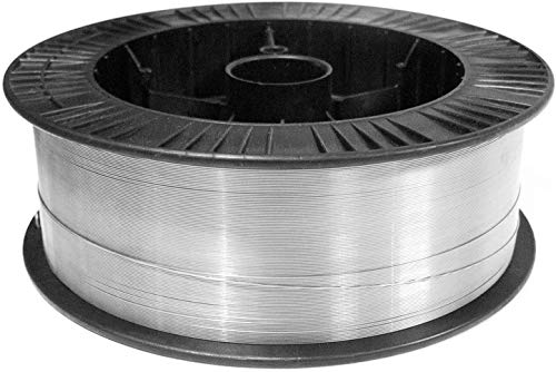
Stainless steel can lose corrosion resistance after welding when the weld area is overheated, not cleaned properly, or matched with the wrong filler. The base metal may still be stainless, but the weld zone can become more vulnerable to rust staining, pitting, and premature attack.
Stainless steel depends on a passive chromium oxide layer for corrosion resistance. Welding disrupts that layer. If the weld overheats, oxygen reacts with the surface and creates heat tint. That discoloration indicates oxide formation and possible chromium depletion near the surface.
When chromium is tied up in oxide scale, the surface cannot protect itself as effectively. In corrosive service, that area can fail before the surrounding base metal.
Heat tint should be treated as a corrosion-control issue. Removing it helps restore surface performance, but removal method matters. Use only cleaning methods approved for the material and the job. Aggressive grinding can damage the surface and create more contamination.
If the application requires higher corrosion resistance, pickling and passivation may be specified. Exact chemistry and process requirements are application-dependent. Unknown (Verify).
For stainless support work, filler selection must be checked before the weld is made. A mismatch may not show immediately, but it can affect long-term performance in service.
For general stainless MIG work, the listed ArcWeld product is:
Discover the premier choice in welding materials with Washington Alloy 33 lb. Spool MIG Wire. This high-quality stainless steel MIG wire is designed specifically for exceptional performance in various welding applications. With a diameter of .035 inches, this 308L stainless steel wire offers the perfect balance of strength and versatility. Crafted for professional welders and DIY enthusiasts alike, Washington Allo…
View at Arc Weld StoreUse the filler only when it matches the job specification and base metal requirements. If the stainless grade or service condition is not confirmed, stop and verify before production welding.
If a weld already shows rust staining or early corrosion, check these points in order:
When corrosion resistance matters, buy and stage stainless wire by verified alloy family, not by wire diameter alone. Keep stainless consumables separated from carbon steel consumables. Label storage clearly. Cross-contamination is a common shop-floor failure mode.
For repeat jobs, document the base metal grade, filler, shielding gas, cleaning method, and post-weld treatment so the same defect does not repeat.
No. But it does indicate oxidation and reduced corrosion margin. The service environment decides how serious it is.
Sometimes. If the damage is only surface oxidation, cleaning and passivation may help. If the weld metal or base metal has already been attacked, repair may be required. Unknown (Verify).
No. ER308L is common for some austenitic stainless applications, but filler choice depends on base metal grade and service conditions. Verify the specification before use.
The weld zone sees heat tint, dilution, and possible contamination. That area often has the weakest passive layer and is the first place corrosion appears.
