• Miller Spoolmatic 30A Parts Diagram: How to Identify Replacement Parts

    Miller Spoolmatic Spool Guns Parts Breakdown

    If you are trying to match a Miller Spoolmatic 30A parts diagram to an actual replacement need, the main task is not just naming a part. It is confirming the exact wear item, the item number on the breakdown, and the condition that caused the failure. On spool guns, small parts can create feeding problems, intermittent arc stability, burnback, or wire damage when they are worn, loose, or installed incorrectly.

    This guide is for welders, maintenance buyers, and support teams who need a practical way to identify replacement parts without guessing. It complements the parts lookup on Weld Support Parts and helps you verify what you are seeing before you order anything.

    Key Takeaways

    • Use the parts diagram to match item numbers first, not just visual shape.
    • Check the gun body, cable ends, trigger, gun tube, drive path, liner path, and consumable end for wear.
    • Do not assume two parts are interchangeable because they look similar. Verify by the diagram and the lookup page.
    • For uncertain details, treat them as Unknown (Verify) until confirmed on the supported lookup page or by direct inspection.

    How to Read the Parts Diagram Correctly

    A parts diagram is a reference map. It shows how the gun is broken into assemblies and item numbers, but it does not replace physical verification. Start by locating the section that matches the problem area:

    • Front end: nozzle, tip, retaining parts, and any front insulator components.
    • Feed path: liner, drive roll-related components, wire guide parts, and inlet/outlet paths.
    • Handle and trigger area: trigger, switch, fasteners, strain relief, and housing pieces.
    • Cable and gun body: power cable, control leads, and connectors.

    Then check the item number on the diagram against the breakdown list. If the page uses a part description that is close but not exact, stop there and verify the actual item number, assembly position, and revision before replacing anything.

    Inspection Steps Before You Replace a Part

    Use these checks before you remove the gun from service:

    1. Inspect the feed path: remove wire and check for shavings, liner damage, tight bends, or contamination.
    2. Inspect the front end: verify the tip, nozzle, and any retaining parts are not burned, worn, or physically loose.
    3. Inspect the trigger action: confirm the trigger returns freely and does not stick.
    4. Inspect cable strain relief: look for cuts, flattening, heat damage, or broken support near the handle and power connection.
    5. Inspect connections: confirm all fittings are secure and there is no movement where there should be none.

    If the symptom is wire feeding failure, do not replace the gun body first. Verify the consumables, liner path, and spool drag condition before moving to larger components.

    Troubleshooting Support: Check, Inspect, Verify

    Check: wire feed speed consistency, trigger response, and whether the wire stops cleanly when the trigger is released.

    Inspect: the nozzle, tip, liner, cable routing, and any points where the wire may catch or birdnest.

    Verify: the exact item number on the parts diagram and match it to the WSP lookup page before ordering a replacement.

    If the gun feeds erratically, the problem may be in more than one place. For example, a worn tip can mimic a liner problem, and a liner problem can mimic spool drag. Replace only the part you have verified as worn, damaged, or out of position.

    WSP Lookup Section

    Use the Weld Support Parts breakdown page here: Miller Spoolmatic Spool Guns Parts Breakdown.

    This lookup page is the starting point for item-number matching, diagram review, and replacement notes. Use it to confirm the support task, not to assume fitment beyond what the page and your own inspection verify. If a detail is not clearly identified, mark it as Unknown (Verify).

    What Usually Matters on a Spool Gun Replacement Job

    Most replacement work on a spool gun comes down to a few practical questions:

    • Is the problem in the consumable end, the feed path, or the cable/trigger assembly?
    • Is the part physically damaged, worn, or simply dirty?
    • Does the diagram item number match the failed component exactly?
    • Do you need one part, or a small set of related parts to solve the issue?

    Do not use a general description alone. A front-end wear item, a liner-related item, and a housing fastener can all appear similar in a quick photo. Verify the location and function before ordering.

    Safety Notes

    • Disconnect welding power before opening the gun or removing parts.
    • Let hot parts cool before handling the nozzle, tip, or front-end hardware.
    • Use eye protection when cutting wire, removing a liner, or cleaning debris from the feed path.
    • Do not force fittings or connectors. If a part does not seat correctly, stop and verify the part number and orientation.
    • Keep the wire secured so it does not unspool unexpectedly during service.

    FAQ

    How do I know which part from the diagram I need?
    Start with the symptom, then inspect the matching section of the gun. Confirm the item number on the diagram and compare it to the WSP lookup page before you order.

    Can I use a similar-looking part if the original is unavailable?
    Do not assume interchangeability. If the page does not clearly confirm fitment, treat the match as Unknown (Verify).

    What should I replace first when wire feeding becomes inconsistent?
    Check the consumable end, liner path, wire condition, and spool drag before replacing larger assemblies. Many feed issues come from wear or contamination in one of those areas.

    Does the diagram tell me how to repair the gun?
    It tells you how the parts are identified and organized. Repair procedure still depends on the actual fault, safe disassembly, and confirmed part condition.

    Sources Checked

    Internal links checked for supporting troubleshooting context:

    Technical details not clearly confirmed on the provided lookup page should be treated as Unknown (Verify).

    Disclosure: As an Amazon Associate, Weld Support Parts may earn from qualifying purchases.

    Related Weld Support Guides

  • TC 70S-2 063 Washington Alloy .030, 33 Lb. 70S-2 MIG Wire, Pack of (1): Application and Buying Checks

    “>TC 70S-2 063 Washington Alloy .030, 33 Lb. 70S-2 MIG Wire, Pack of (1)

    TC 70S-2 063 Washington Alloy .030, 33 Lb. 70S-2 MIG Wire, Pack of (1) is a solid MIG wire intended for gas metal arc welding on mild and low-alloy steel. For buyers and maintenance teams, the main question is not only whether the wire will weld, but whether it matches the joint condition, wire feeder setup, and procedure requirements in your shop. This guide focuses on application checks, fitment checks, and practical verification steps before you commit to a spool.

    Key Takeaways

    • ER70S-2 class solid wire is commonly selected for mild and low-alloy steels where stable feeding and weld quality matter.
    • Wire diameter, spool size, drive-roll setup, liner condition, and contact tip size all need verification before use.
    • Do not assume the wire will overcome poor prep; clean base metal still gives better results.
    • If procedure approval matters, verify the WPS and any filler metal listing before release to production.

    What this wire is for

    Based on the available product information, this is a .030 in (0.8 mm) solid MIG wire in the ER70S-2 family, supplied on a 33 lb spool. That makes it a common size for general fabrication, repair work, and light-to-medium production welding on carbon steel. The added deoxidizers associated with ER70S-2 chemistry can help in situations with light mill scale or minor surface contamination, but they do not replace cleaning, fit-up control, or procedure compliance. Best results still come from clean base metal.

    Use this wire as a candidate when you need a general-purpose carbon steel MIG wire and your equipment is configured for .030 in solid wire. If your job is governed by a written WPS, the WPS controls. If the wire is being selected for maintenance repair without a formal WPS, verify the joint type, shielding gas, deposition target, and feeder setup before purchase or installation. Unknown (Verify) for any application outside mild and low-alloy steel service.

    Buying checks before you order or load the spool

    Check wire diameter. Confirm the feeder, gun, and contact tip are set up for .030 in wire. A mismatch can cause erratic feeding, burnback, or inconsistent arc starting.

    Inspect spool compatibility. Confirm that your feeder accepts the spool format and weight. The product listing indicates a 33 lb spool, but always verify your machine’s maximum spool size and hub capacity. Unknown (Verify) if your feeder has a narrow spool compartment or light-duty hub.

    Verify shielding gas. ER70S-2 solid wire normally runs with shielding gas, but the exact mix depends on your procedure and base metal. Do not assume a gas type from the wire class alone. Check the WPS or internal process sheet.

    Check drive-roll and liner setup. Solid wire generally feeds best with the correct groove profile, proper tension, and a clean liner. If the feeder was last used with flux-cored wire, inspect drive-roll selection and liner wear before loading this spool.

    Inspect contact tip wear. A worn tip can look like a wire problem. Replace tips that are ovaled, burned, or loose.

    Application and process checks

    Check base metal condition. ER70S-2 can be more forgiving than basic wire on slightly imperfect surfaces, but do not use that as a substitute for cleaning. Remove oil, rust, heavy mill scale, paint, moisture, and weld residue wherever practical.

    Verify joint access and polarity. Confirm the gun can maintain a stable arc length and that the machine polarity matches the process setup required by your WPS or equipment instructions. If you do not have that documentation, verify it before starting production.

    Inspect fit-up. Poor gap control can hide under a good-looking bead. Check root opening, alignment, and tack quality before blaming the wire.

    Confirm feed consistency. Test feed the wire through the gun cable with the machine cold. Look for drag, birdnesting, or intermittent push. If the wire does not feed smoothly on setup, fix the feeder first.

    Verify arc behavior on coupon. Run a short test on scrap from the same material family. Inspect bead shape, spatter level, wetting, and tie-in. If results are inconsistent, compare gas flow, tip condition, liner wear, and feed speed before changing wire class.

    Troubleshooting support: check, inspect, verify

    If the arc is unstable: check gas flow, inspect for leaks or loose fittings, and verify tip-to-work distance and stickout against your procedure.

    If feeding is rough: check drive-roll tension, inspect the liner for wear or contamination, and verify the correct tip size for .030 in wire.

    If spatter is excessive: check voltage and wire feed settings, inspect ground connection quality, and verify the shielding gas setup before changing product.

    If weld appearance is inconsistent: inspect base metal cleanliness, verify travel speed, and check joint fit-up. Do not assume the spool is at fault until the machine and preparation are reviewed.

    WSP lookup and filler metal finder

    For procedure-controlled work, use the Weld Support Parts lookup tools as starting points, then verify against the approved WPS or engineering release. These pages help with selection and comparison, but they are not a substitute for procedure approval.

    If your job requires documented filler approval, use those pages to narrow the candidate list, then confirm the final selection against your internal welding documentation. Treat the result as a starting point, not a guaranteed procedure match.

    Safety notes

    Handle wire spools carefully. Edges can be sharp, and loose wire ends can whip back during loading. Wear gloves when opening packaging, setting a spool, or trimming wire. Keep the feeder powered down during installation. Verify ventilation and fume control before welding. Follow your site’s hot-work controls, especially on painted or contaminated material.

    FAQ

    Is this wire only for mild steel?
    The provided product information supports use on mild and low-alloy steel. Unknown (Verify) for other base metals or special applications.

    Can I use it on lightly scaled material?
    ER70S-2 chemistry may help tolerate light mill scale or minor contamination, but that is not a license to skip cleaning. Inspect the surface and clean it as much as the job allows.

    Do I need a specific gas or procedure?
    Verify your shielding gas and procedure from the WPS or internal welding instructions. Do not select gas solely from the wire class.

    How do I know if the spool will fit my feeder?
    Check the feeder’s spool diameter, hub design, and maximum weight rating. If the machine documentation is unavailable, measure and verify before purchase or install.

    Sources Checked

    • Provided ArcWeld product reference for TC 70S-2 063 Washington Alloy .030, 33 Lb. 70S-2 MIG Wire, Pack of (1)
    • WSP lookup page
    • WSP filler metal finder
    • Allowed internal links provided in the task

    Final verification should always come from the active WPS, machine manual, and shop qualification records.

    Related Arc Weld Part

    TC 70S-2 063 Washington Alloy .030, 33 Lb. 70S-2 MIG Wire, Pack of (1)

    TC 70S-2 063 Washington Alloy .030, 33 Lb. 70S-2 MIG Wire, Pack of (1)

    Washington Alloy TC 70S-2 04 is an ER70S-2 solid MIG (GMAW) wire for welding mild and low-alloy steels where consistent feeding and sound weld quality matter; ER70S-2 chemistry includes added deoxidizers that can help tolerate light mill scale and minor surface contamination versus standard ER70S-6 (best results still come from clean base metal). This item is one (1) spool of .030 in (0.8 mm) wire, 33 lb (0.91 kg)…

    View at Arc Weld Store

    Related Weld Support Guides

  • ERNiFeCr-2 TIG / GTAW Filler Metal: Selection and Compatibility Checks

    ERNiFeCr-2 TIG / GTAW Filler Metal

    ERNiFeCr-2 is a TIG/GTAW filler metal classification used for certain nickel-iron-chromium alloy applications. It is not a universal replacement for other nickel filler metals, and it should not be selected by alloy family alone. Before ordering rod or striking an arc, verify the welding procedure specification, base metal grade, service conditions, and the filler metal manufacturer’s data sheet.

    Key Takeaways

    • Use ERNiFeCr-2 only when the WPS and base metal call for it.
    • Do not assume equivalency with ERNiCr-3, ERNiCrMo-3, or other nickel fillers without procedure approval.
    • Confirm heat resistance, corrosion exposure, and post-weld service requirements before selecting a rod.
    • Check diameter, tungsten setup, shielding gas, and joint access before release to production.
    • When uncertain, treat the catalog page as a starting point and verify against the governing code or engineering document.

    What ERNiFeCr-2 Is Used For

    ERNiFeCr-2 is associated with TIG/GTAW filler selection for compatible high-temperature nickel alloys, including Incoloy and nickel-iron-chromium alloys. That description is broad on purpose. In actual fabrication and repair work, the correct filler depends on the base metal chemistry, operating temperature, corrosion environment, and whether the work is new construction, repair, or overlay.

    Do not use a label like “nickel alloy filler” as the only selection criterion. Nickel systems vary widely in iron, chromium, molybdenum, and other alloy content. A filler that works for one alloy may be wrong for another, even when the parts look similar.

    Compatibility Checks Before You Weld

    Use the following check, inspect, and verify sequence before release.

    1) Check the WPS first

    Check the WPS for the exact filler classification, process, base material group, joint design, shielding gas, and preheat or interpass limits. Verify whether the procedure allows ERNiFeCr-2 specifically or whether it lists another classification. If the WPS is missing, outdated, or written for another job, stop and get engineering or quality approval.

    2) Inspect the base metal identification

    Inspect the part markings, heat numbers, mill test documentation, or repair records. Verify the actual base metal grade, not just the alloy family. For nickel alloys, small differences in chemistry can change weldability and service performance. If the metal cannot be positively identified, mark it Unknown (Verify) until confirmed.

    3) Verify service conditions

    Verify whether the component will see elevated temperature, thermal cycling, corrosive media, or cyclic loading. A filler chosen for general compatibility may still fail in service if the weld must resist oxidation, carburization, chloride exposure, or repeated thermal shock. If the service environment is not documented, treat it as Unknown (Verify).

    4) Inspect joint condition and prep

    Inspect the joint for oil, oxide, paint, scale, and contamination. Nickel alloys are sensitive to surface condition. Clean with approved methods only. Verify edge preparation, fit-up, root opening, and access for torch angle and filler feed. Poor prep often shows up later as lack of fusion, inclusions, or unstable arc starts.

    5) Verify wire diameter and handling

    Verify the rod diameter against the joint thickness and deposition rate target. The provided product data does not state a guaranteed size range here, so any exact diameter selection is Unknown (Verify) unless the WPS or data sheet confirms it. Store filler rods clean and dry. Do not assume a rod left open on the floor is acceptable for critical work.

    Filler Selection Pitfalls

    One common mistake is substituting by similarity. Maintenance teams often see “nickel” on the drawing and choose the nearest available rod. That approach can create dilution problems, mismatch in thermal expansion, or inadequate corrosion resistance. Another mistake is ignoring code requirements. Some jobs require a specific filler under a construction code, repair standard, or OEM instruction. If the document calls for another filler, ERNiFeCr-2 is not automatically acceptable.

    If you are comparing options, use the filler metal finder as a starting point only, not as final approval. The finder can narrow the search, but it does not replace the WPS, code, or manufacturer data sheet.

    WSP Lookup and Selection Reference

    For the product reference and selection context, review the ERNiFeCr-2 page here: ERNiFeCr-2 TIG / GTAW Filler Metal.

    For broader comparison and selection support, use the filler metal finder here: Weld Support Parts Filler Metal Finder.

    Use both pages as starting points only. They help with classification-level selection, but they do not guarantee procedure approval, code compliance, or service suitability.

    Practical Shop and Field Checks

    • Check polarity and machine setup: Verify the GTAW power source is set to the procedure requirements.
    • Inspect shielding gas delivery: Verify flow, leaks, hose condition, and cup coverage.
    • Check tungsten condition: A contaminated or improperly ground tungsten can destabilize the arc.
    • Verify cleanliness: Remove oxidation and surface contamination before welding.
    • Inspect the first bead: Confirm wetting, bead shape, and fusion at the toes.
    • Verify interpass condition: Clean each pass and confirm temperature stays within procedure limits.

    If arc behavior is erratic, compare your setup with the internal TIG support articles on tungsten contamination, arc wandering, and cup size selection. These references are useful when the filler is correct but the weld still performs poorly due to torch setup or shielding issues.

    Safety Notes

    • Use approved ventilation and fume control for all nickel-alloy welding.
    • Wear eye, face, hand, and body protection appropriate for TIG/GTAW.
    • Do not weld on an unidentified alloy without verification.
    • Allow hot parts to cool before handling; nickel alloys can retain heat.
    • Follow the site’s lockout, hot work, and confined-space rules where applicable.

    FAQ

    Is ERNiFeCr-2 the same as other nickel TIG fillers?

    No. It is a specific classification, and substitution is not automatic. Verify the WPS and the base metal before using it.

    Can I use ERNiFeCr-2 on any Incoloy part?

    No. “Incoloy” is a family term, not a single grade. Verify the exact alloy grade, service conditions, and required filler on the WPS or engineering document.

    Do the product pages guarantee compatibility?

    No. The product page and finder are selection starting points only. Final compatibility comes from procedure approval, base metal identification, and manufacturer documentation.

    What if the base metal is not clearly identified?

    Treat it as Unknown (Verify). Do not weld until the material is confirmed by records, testing, or authorized engineering review.

    Sources Checked

    Disclosure: As an Amazon Associate, Weld Support Parts may earn from qualifying purchases.

    Related Weld Support Guides

  • Lincoln Viking 3350 Battery Replacement: Parts and Fit Checks

    Lincoln Viking 3350 Helmet Parts Breakdown

    If you are searching for lincoln viking 3350 battery, the first step is to confirm which part actually needs replacement. On a welding helmet, battery-related complaints can come from the battery itself, the auto-darkening filter (ADF) power system, the cartridge, wiring contacts, or a simple fit issue that prevents proper power transfer. For the Lincoln Viking 3350, the correct path is to verify the helmet model, inspect the battery compartment or power source area, and compare the replacement part against the helmet you have in hand before ordering.

    Key Takeaways

    • Do not assume every darkening problem is a battery failure.
    • Check the helmet model number and revision before buying parts.
    • Inspect contacts, cartridge fit, and battery access points for damage or contamination.
    • Use the WSP lookup page as the main starting point for Lincoln Viking 3350 support parts.
    • If a detail is not visible on the helmet or listed on the support page, treat it as Unknown (Verify).

    Start With the Helmet Model

    Before replacing anything, confirm that the helmet is actually a Lincoln Viking 3350. The Viking line has multiple versions and related accessories, and similar-looking parts may not fit across models. Check the outside label, inside shell markings, or documentation that came with the helmet. If the identification is unclear, treat the exact revision as Unknown (Verify).

    This matters because battery access, ADF cartridge design, and headgear hardware can vary by helmet family. A part that looks close enough may still fail to seat correctly or may not make electrical contact.

    What to Inspect Before You Replace the Battery

    Use a simple check-inspect-verify routine:

    • Check the lens for low-power symptoms, delayed darkening, or intermittent operation.
    • Inspect the battery area, cartridge face, and contact points for dirt, spatter, corrosion, or moisture.
    • Verify whether the battery is replaceable as a separate part or whether the ADF assembly is the serviceable unit. If the service path is not clear, mark it Unknown (Verify).

    Also inspect the helmet shell for heat damage around the front cartridge opening. Excess heat or impact can distort the fit and create symptoms that look like battery failure. If the shell is warped, a fresh battery may not solve the issue.

    Fit Checks for a Replacement Battery or Power Component

    When a replacement battery or internal power component is available for the helmet, fit checks should happen before installation is considered complete:

    1. Match the physical form of the replacement to the original component. Compare size, tab location, contact placement, and mounting style.
    2. Check polarity and seating. The component should install without forcing, bending, or shaving material.
    3. Inspect contact pressure. Loose contacts can create intermittent power loss and false failure reports.
    4. Confirm cover alignment. Any battery door, retaining frame, or cartridge cover should close fully and stay secure.
    5. Test function after install. Verify that the helmet powers on and responds under normal working conditions.

    If the battery is not clearly shown as a standalone replacement on the support page, do not guess. A battery-like symptom may point to another ADF component, and the correct replacement may be the lens cartridge or another support part rather than a loose cell.

    WSP Lookup: Lincoln Viking 3350 Support Page

    Use the Weld Support Parts lookup page here: Lincoln Viking 3350 Helmet Parts Breakdown.

    This page is the best starting point for replacement support because it is built around the Viking 3350 helmet and its common support items, including lens, ADF cartridge, and headgear-related parts. Use it to compare what you need against the helmet you have. Do not rely on assumptions from a similar helmet or a forum photo if the fit detail is not confirmed.

    Common Failure Symptoms That Are Not Always a Battery Problem

    Welding support teams see the same symptom reported as “battery dead” when the real issue is elsewhere. Check these areas first:

    • Intermittent darkening may point to dirty sensors, a damaged cartridge, or poor contact.
    • No response may be a drained battery, but it can also be a failed cartridge or broken wiring path.
    • Delayed switching can come from low power, blocked sensors, or contamination on the lens surface.
    • Power loss after impact often suggests internal damage or a loose fit rather than battery age alone.

    Verify sensor windows are clean and unobstructed. Check the front cover lens and grind shield for damage that could block light sensing. If cleaning restores operation, the battery may not have been the cause.

    Replacement Procedure: Practical Order of Work

    For maintenance buyers and technicians, the safest order is simple:

    1. Identify the exact helmet model.
    2. Inspect the battery area and ADF face.
    3. Confirm whether the suspected part is listed on the WSP support page.
    4. Compare the old part to the replacement for size, mounting, and contact layout.
    5. Install without forcing fit.
    6. Test the helmet through a normal welding check.

    If any step does not match, stop and verify the part number or service path. Unknown fit information should stay Unknown (Verify) until confirmed through the support listing or the removed part itself.

    Safety Notes

    • Remove the helmet from service if it will not darken reliably.
    • Do not weld with a helmet that has loose internal parts or a damaged cartridge.
    • Do not force battery covers, cartridge frames, or retaining clips into place.
    • Keep moisture, grinding dust, and spatter out of the electronics area.
    • If the helmet has visible shell damage, inspect the full assembly before returning it to service.

    FAQ

    How do I know if the Lincoln Viking 3350 battery is actually bad?
    Check for repeatable low-power symptoms after cleaning the contacts and verifying the cartridge fit. If the problem persists, compare the removed part to the support page and the helmet hardware. If the battery type or service method is not confirmed, it is Unknown (Verify).

    Can I use a similar battery from another Viking helmet?
    Do not assume interchangeability. Similar appearance does not guarantee fit, contact layout, or proper operation. Verify against the exact Viking 3350 support listing before ordering or installing anything.

    What if the helmet still does not work after battery replacement?
    Inspect the ADF cartridge, sensors, cover lenses, and contact points. A bad battery is only one possible cause. If the power path is unclear, the issue may be in a different helmet component.

    Where should I start when looking for Lincoln Viking 3350 support parts?
    Start with the WSP lookup page for the Lincoln Viking 3350 and compare the helmet in hand to the listed parts breakdown before deciding what to replace.

    Sources Checked

    Use the support page first, verify the helmet in hand, and replace only the part that matches the failure mode. That approach prevents wrong-part orders and reduces downtime.

    Disclosure: As an Amazon Associate, Weld Support Parts may earn from qualifying purchases.

    Related Weld Support Guides

  • The Booth Next Door: What Welding Students Teach Each Other

    A welding booth gives one student a place to practice. A good lab also teaches a room full of future welders how to watch out for the work—and for one another.

    In a welding lab, the lesson rarely stays inside one booth. An arc goes quiet. A hood comes up. Someone studies a coupon, turns it toward the light and walks two stalls over to ask, “What are you seeing?”

    That small exchange is part of learning the trade. An instructor sets the standard and keeps the room safe, but students also learn from the work happening beside them: how another person lays out a practice piece, reacts to a bad start, organizes a lead or cleans a station before the next group arrives.

    The best peer learning is not a shortcut around instruction. It is practice in becoming the kind of shopmate other people can work beside.

    A booth looks individual. The work is shared.

    The curtain suggests solitude. The ventilation, traffic and pace of the room say otherwise.

    OSHA’s general welding requirements call for adjacent workers to be protected from arc rays by appropriate screens, shields or eye protection. The same standard says booth screens must not seriously restrict ventilation. Those are employer responsibilities, not a student rulebook, but they show why a training lab is a shared system. One person’s open curtain, misplaced screen or blocked aisle can affect somebody who never touches that person’s work.

    New students begin to understand the room through repeated, ordinary habits. Close the screen. Route leads so they do not become a surprise underfoot. Keep hot material where another person will not grab it by mistake. Return shared tools. Leave the booth ready for the next welder instead of leaving a small excavation project on the table.

    None of those habits will make a beautiful social-media clip. Every one of them makes a lab—and later a shop—easier to trust.

    Useful feedback has a shape

    “Looks good” is encouragement. It is not much of a diagnosis.

    A useful classmate points to something observable: where the arc started, how the joint was fit, what changed halfway down the coupon or which part of the finished piece deserves a closer look. The goal is not to perform expertise. It is to help the other person form a better question for the instructor.

    That distinction matters because similar-looking problems can have different causes. Copying the settings from the booth next door may change the evidence without explaining it. A student who says, “Your second half looks different from your first—what changed?” is often more helpful than one who reaches for the machine controls.

    Good peer feedback also knows where it stops. Anything involving safety, equipment condition, procedure requirements or an unfamiliar material belongs with the instructor or the person responsible for the lab. The confident move is not guessing faster. It is knowing when another set of qualified eyes is needed.

    The curriculum is bigger than the bead

    The American Welding Society describes SENSE as a framework of minimum standards and guidelines that schools can use to build welding programs. At the entry level, its subjects include welder safety and health, drawing and welding-symbol interpretation, thermal cutting and the major arc-welding processes. That list makes a quiet point: learning to weld was never only about making the face of a practice bead look right.

    Students are learning a working language. They begin connecting a drawing to a joint, a process to its hazards, and a finished coupon to an honest evaluation. The person in the next booth can help build that language by asking a clean question, comparing notes without turning the lab into a contest and accepting correction without making the correction personal.

    This is where class culture starts to matter. A room that treats every mistake as entertainment teaches people to hide evidence. A room that treats a mistake as information gives people a chance to correct it. Welding will supply enough frustration on its own; classmates do not need to add theater.

    School ends. Training does not.

    The Bureau of Labor Statistics says welders commonly enter the occupation through a combination of technical and on-the-job training. It also notes that some workers come through employer-based apprenticeships and that even people with formal technical training receive additional training after they are hired.

    In other words, the first job does not erase the student role. It changes the room.

    The booth next door becomes the fitter at the other end of the table, the senior welder on the next station, the inspector reading the same joint from another angle or the new hire watching how the crew handles a restart. The habits formed in school travel well: ask what someone sees, describe the evidence, respect the procedure and hand safety questions to the right person.

    So does the habit of leaving a place ready for whoever follows. A labeled coupon, a cleared table and a returned tool say something simple: another person’s time counts too.

    The classmate people remember

    Years later, few welders will remember every practice plate from school. They may remember the student who could explain something without showing off. The one who called an instructor over when a situation felt wrong. The one who did not laugh when somebody struggled with a process that had come easily to everyone else.

    That person is already practicing a trade skill. Not a welding process, exactly, but the human part of production: being clear, steady and useful when another worker needs a second set of eyes.

    Community question: Who helped you most when you were learning to weld—and what did they do that made the lesson stick?

    Arc Life tells the human side of the trade, from the first practice booth to the crews that keep learning on the job. Read what Arc Life is building, then visit the Arc Life collection.

  • The Small Part That Stops the Shift: A Better Way to Track Welding Consumables

    The part that stops a welding shift is not always expensive. Sometimes it is a contact tip, a plasma electrode, a grinding wheel, a tungsten size nobody checked, or the last pair of the correct gloves. The dollar value may be small. The interruption is not.

    That is what makes shop consumables easy to underestimate. Individually, they look like minor purchases. Together, they form the daily operating layer between a stocked shop and a stalled one. When no one has a dependable count, ordering becomes a cycle of emergency runs, overbuying familiar items, and discovering shortages only after the job is already set up.

    A useful inventory system does not need to behave like a warehouse platform. For many welding and fabrication shops, it needs to do a few basic things consistently: identify the item, record what is physically on hand, define when attention is required, show what should be reviewed for reorder, and preserve enough usage history to spot a pattern.

    The physical count remains the truth

    Usage logs are helpful, but welding shops are messy places for perfect transaction data. A contact tip gets handed to another booth. A sleeve of electrodes moves to a field truck. Abrasives are pulled during second shift and entered later—or not at all. If every missed entry automatically changes the official count, the spreadsheet becomes confidently wrong.

    A better small-shop approach is to keep the physical count authoritative. Use logged usage to understand velocity and forecast pressure, then reconcile the master quantity through an actual count. That separation makes the forecast useful without pretending the log captured every movement.

    A reorder point is a decision trigger

    A reorder point is not the same as an automatic purchase order. It is the quantity that tells someone to stop and review the item. The right threshold depends on usage, supplier lead time, package quantity, job requirements, storage limits, and the cost of being wrong.

    For a steady-use item with a dependable supplier, the threshold may be simple. A specialized torch component or PPE item with a long lead time deserves more margin. A useful reorder list should bring those decisions together: current count, reorder point, suggested quantity, estimated cost, preferred supplier, and the person responsible for approving the purchase.

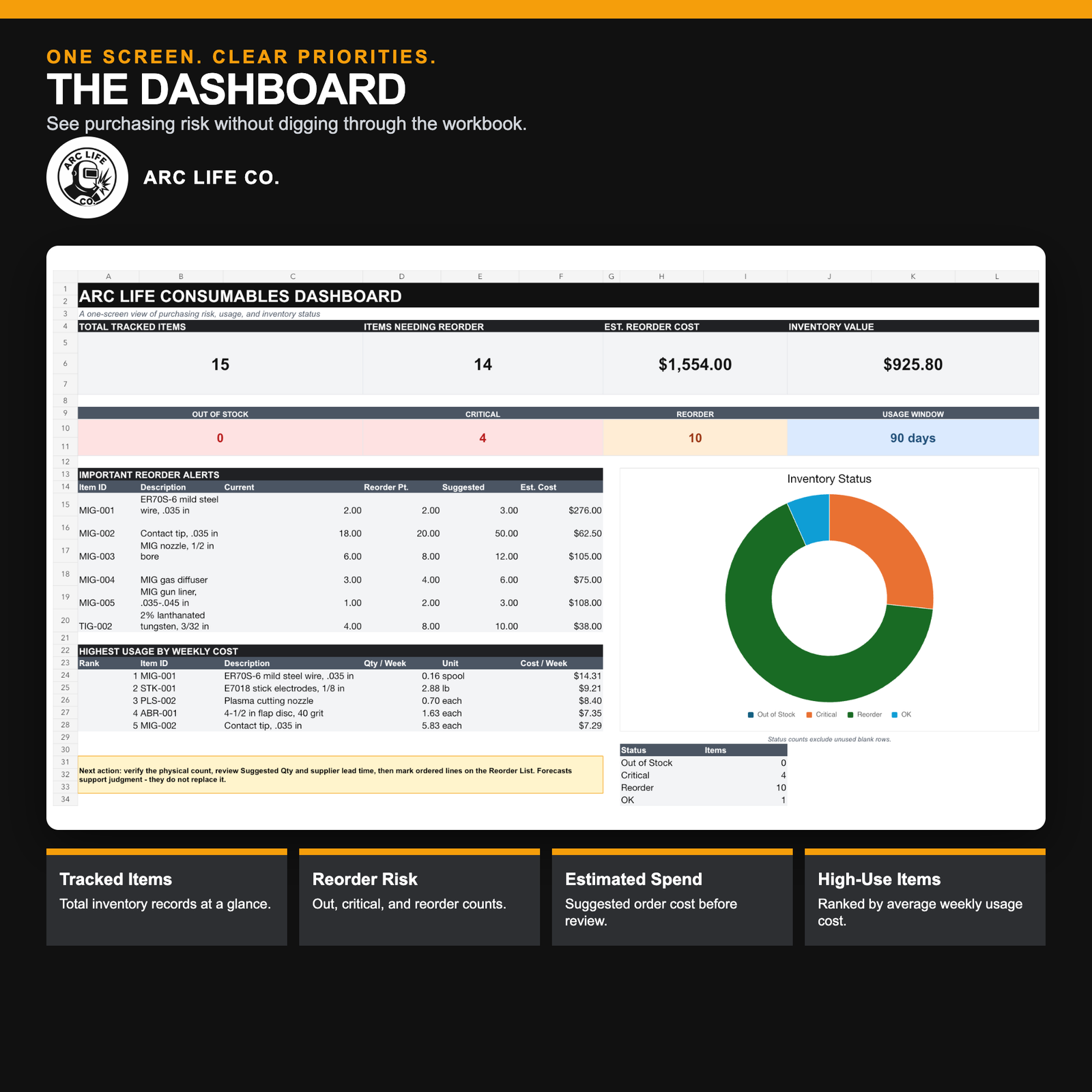
    Arc Life welding shop consumables dashboard showing reorder alerts, estimated spend, inventory status, and high-use items
    The dashboard turns count and usage records into a short purchasing-risk review; it does not place or approve an order.

    Burn rate is useful when it stays humble

    Average weekly usage can help identify items that deserve closer attention. It can also estimate how many days of stock may remain. Those numbers are planning signals, not promises. A rush job, a new operator, a process change, scrap, or an incomplete log can shift the result quickly.

    The same restraint applies to downtime estimates. Multiplying labor and production exposure by the hours lost can make a cheap stockout visible to management. It does not turn the estimate into an accounting entry. The point is to compare the cost of reasonable stock with the operational consequence of having none.

    One review beats five emergency messages

    The process works best when it has a cadence. Count the critical items, review anything at or below its reorder point, verify suggested quantities and supplier details, mark what has been ordered, and check high-use items for unusual movement. A ten-minute review on a fixed day is more dependable than waiting for five people to report shortages in five different ways.

    That review should include more than filler metal and torch parts. Plasma consumables, abrasives, PPE, gas-handling accessories, shop chemicals, saw blades, and other recurring items all compete for attention. The useful categories are the ones that match the way the shop actually buys, stores, and uses material—not the categories that look neat in a template.

    A practical starting system

    The Arc Life Welding Shop Consumables Manager is an Excel-based system designed around that small-shop workflow. It includes a master inventory, reorder list, usage log, burn-rate analysis, downtime cost calculator, dashboard, setup lists, a quick-start guide, and five printable forms. It uses standard formulas and contains no macros. The current workbook supports up to 200 recurring consumables.

    It deliberately does not subtract every logged use from the official count, connect to suppliers, create purchase orders, or place orders. Those limits matter. The physical count remains authoritative, and a person still verifies the unit, quantity, price, supplier, and purchasing decision before acting. Excel 2019 or later is recommended because other spreadsheet applications may alter formulas, charts, validation, or print settings.

    The value is not that the workbook “knows” what to buy. It gives the shop one place to see what is low, what is moving, and what deserves a decision before the next shift starts looking for a part that should have been on the shelf.

    Shop question: Which low-cost consumable has caused the most expensive interruption in your shop?

    See both shop-management systems in the Arc Life Digital Tools collection.

  • ERNiCu-7 TIG / GTAW Filler Metal: Filler Metal Finder Notes

    ERNiCu-7 TIG / GTAW Filler Metal

    ERNiCu-7 TIG / GTAW filler metal is used as a starting point for nickel-copper alloy work, including Monel-type applications. The label tells you the filler family, but it does not confirm the weld procedure, the base metal grade, the service condition, or the final code requirement. Before you order rod or strike an arc, verify the WPS, the drawing notes, the alloy identification, and the manufacturer data sheet.

    Key Takeaways

    • Use ERNiCu-7 as a selection starting point, not as automatic approval for production welding.
    • Confirm base metal grade first. Monel-type alloys are not all the same.
    • Verify service conditions, especially corrosion exposure and temperature limits, against the job requirements.
    • Check the WPS and code references before you commit to a filler metal lot or diameter.
    • If the purchase order or print is unclear, stop and verify with the responsible engineer or welding coordinator.

    What ERNiCu-7 Covers at a Practical Level

    The WSP filler metal finder page lists ERNiCu-7 under TIG / GTAW filler metal support, with AWS A5.14 as the referenced specification and Monel and nickel-copper alloys as the base material group. That is useful for narrowing the search, but it is still only a starting point. The page also shows related search terms such as ERNi-1 and common rod diameters, but you still need to confirm what your job actually requires.

    Use the ERNiCu-7 TIG / GTAW filler metal page as the product reference point. Use the WSP filler metal finder to compare other filler families when the base metal, joint design, or service environment changes.

    Troubleshooting and Support Checks

    If you are trying to match a filler to an old repair job, a maintenance shutdown, or a mixed-material assembly, work through the problem in order.

    Check the base metal

    • Inspect the material tag, mill cert, drawing, or PMI record.
    • Verify whether the base metal is actually Monel-type or another nickel alloy.
    • Do not assume a visually similar alloy is acceptable.

    Inspect the code and WPS requirements

    • Check whether the job is governed by a code, internal procedure, or customer specification.
    • Verify the accepted filler classification on the WPS.
    • If the filler classification is not listed, stop and request clarification.

    Verify the service environment

    • Confirm whether the part sees seawater, chemical exposure, elevated temperature, or cyclic loading.
    • Check whether corrosion resistance or crack resistance is the primary requirement.
    • Where service conditions are unclear, mark them as Unknown (Verify) and escalate before welding.

    Inspect the filler rod details before use

    • Verify the classification on the package: ERNiCu-7.
    • Confirm the diameter required by the procedure. The WSP page references common sizes, but the correct size for your job is Unknown (Verify) unless the WPS states it.
    • Check the manufacturer data sheet for handling, storage, and any limitations.

    Selection Guidance for Buyers and Weld Support Teams

    For buyers, the main risk is ordering filler by name only. For welders, the main risk is starting with a rod that looks right but does not match the WPS or service environment. For maintenance teams, the main risk is assuming a field repair can follow the same filler choice as the original fabrication.

    Use this workflow:

    1. Identify the base metal grade.
    2. Review the WPS or repair instruction.
    3. Check the environment and service duty.
    4. Confirm the filler classification.
    5. Verify the rod diameter, packaging, and storage condition.
    6. Only then release the purchase or begin welding.

    Common Support Questions

    Is ERNiCu-7 the correct choice for every Monel repair? No. Monel-type alloys vary, and the correct filler depends on the exact base metal grade, the procedure, and the service environment.

    Can I use the filler finder page as approval for welding? No. The finder page is a selection aid. It does not replace code review, WPS approval, or manufacturer data.

    Do rod diameters on the page guarantee stock availability? No. Availability is Unknown (Verify) unless confirmed by the supplier or current listing.

    Safety Notes

    • Follow the active WPS, PPE requirements, and ventilation practices for nickel alloy welding.
    • Do not weld on unidentified material without verification.
    • Keep filler metal clean, dry, and segregated from unverified stock.
    • When in doubt, pause and verify before work continues.

    FAQ

    What is ERNiCu-7 used for?

    It is a TIG / GTAW nickel-copper filler metal used as a starting point for Monel and nickel-copper alloy applications. Final use still depends on the WPS and service requirements.

    Is the WSP filler metal finder a final approval tool?

    No. It is a support tool for narrowing filler selection. It does not replace procedure approval, code review, or manufacturer documentation.

    What should I verify before ordering ERNiCu-7 rod?

    Verify the base metal grade, the WPS, the applicable code, the service environment, the required rod diameter, and the manufacturer data sheet. If any item is unclear, treat it as Unknown (Verify).

    Can I substitute another nickel alloy filler without review?

    No. Substitution requires technical review. Different nickel alloy fillers can behave differently in corrosion service, strength, and crack resistance.

    Sources Checked

    Use these pages as reference points only. Confirm the WPS, code requirements, base metal grade, service conditions, and manufacturer data sheet before ordering or welding.

    Disclosure: As an Amazon Associate, Weld Support Parts may earn from qualifying purchases.

  • Norton 61463624566 1 x 1 in. 1/4 Spindle Gemini Mounted Point W220: Replacement Part Breakdown

    The Norton 61463624566 1 x 1 in. 1/4 Spindle Gemini Mounted Point W220 is a small abrasive component used in grinding and finishing work where controlled contact is needed. For buyers and maintenance teams, the main question is not only what the product is, but whether it matches the tool, spindle, and job requirements already in service. This breakdown keeps the focus on fit, inspection, and replacement logic, not guesswork.

    Product-specific technical details beyond the name provided are Unknown (Verify). That includes exact abrasive composition, bond type, maximum operating speed, and application limits. Verify those points against the manufacturer listing and the tool manual before use.

    Key Takeaways

    • Confirm the spindle size and mounting method before ordering or installing.
    • Do not assume a mounted point is interchangeable with other Gemini shapes or grit structures.
    • Inspect for damage before first run and after any impact or drop.
    • Use the tool maker’s speed and guard requirements, not assumptions from the part name.
    • If technical data is missing, treat it as Unknown (Verify) until confirmed from the source page or packaging.

    What This Part Is Used For

    A mounted point is a bonded abrasive on a small shank or spindle-style mount. In maintenance and fabrication work, these parts are commonly used for deburring, blending, edge cleanup, and limited-access grinding. The exact use depends on the abrasive grade, shape, and spindle support system. For this Norton item, the available identification is limited to the product name and ASIN reference. Anything further should be verified before the part is placed in service.

    Replacement Part Breakdown

    When a mounted point is treated as a replacement part, break the decision into four checks:

    1) Tool interface

    Verify the spindle diameter, collet, or holder requirement. The title references a 1/4 spindle, but the actual fit should be confirmed on the tool and on the listing. Do not force a shank into a holder that is undersized or worn.

    2) Shape and working envelope

    The mounted point size is listed as 1 x 1 in. Confirm that the physical profile clears guards, housings, and adjacent work surfaces. In cramped repair work, a part that fits the holder may still be too large for the access window.

    3) Abrasive behavior

    W220 appears in the title, but the meaning of that designation should be verified against the product source. Do not use the code alone to decide aggressiveness, finish level, or material removal rate.

    4) Wear and replacement threshold

    Replace the point when the shape is no longer usable for controlled contact, when the bond is cracked, or when balance is affected. Mounted points that are chipped, glazed, or visibly out of round should be removed from service and inspected before reuse.

    Check, Inspect, Verify Before Use

    Check the part number on the package and the shank or spindle dimensions on the tool. Confirm the part is intended for the mounted point holder in use.

    Inspect the abrasive for cracks, edge chips, glazing, contamination, and storage damage. Check that the shank is straight and that the body is not visibly eccentric.

    Verify the operating speed limit, allowed work materials, and guard requirements from the manufacturer and tool documentation. If those details are missing, treat them as Unknown (Verify) and stop until confirmed.

    Troubleshooting Support

    If the mounted point runs poorly, the issue is often fit, damage, or operating method rather than the part name itself.

    • Vibration at startup: Check for a bent spindle, damaged holder, or out-of-round abrasive body.
    • Poor finish: Inspect for glazing, loading, or using the wrong abrasive grade for the material.
    • Fast wear: Verify contact pressure and dwell time. Excess force shortens life and can overheat the work.
    • Grinding chatter: Confirm the holder is tight and the tool bearings are in good condition.
    • Visible cracking: Remove from service immediately. Do not attempt to dress or repair a cracked mounted point.

    If a replacement is being sourced for a production or maintenance program, keep the old sample until the new part is checked against it. A direct side-by-side comparison is often the fastest way to catch dimension mismatches.

    Product and Parts Notes

    This page covers the single identified product: Norton 61463624566 1 X 1 In. 1/4 Spindle Gemini Mounted Point W220. The verified Amazon registry reference provided for this draft is ASIN B01M1CIBDL. No additional product specs are being inferred here.

    For related abrasive support reading, see our internal review of a Norton Gemini grinding wheel here: Norton Gemini Fast Cut Grinding Wheel Review (4-1/2″ × 1/4″ × 7/8″, Pack of 25). That article is a separate product category, but it is useful for comparing how Norton abrasive naming and support decisions are handled across grinding products.

    Safety Notes

    • Wear eye protection and appropriate face protection for grinding work.
    • Use the tool guard and follow the tool manufacturer’s installation instructions.
    • Do not exceed the rated speed. If the speed rating is Unknown (Verify), do not run the part until the value is confirmed.
    • Keep hands clear of the rotation path and do not touch the point immediately after use.
    • Remove damaged or dropped abrasives from service.

    FAQ

    Is the Norton 61463624566 mounted point interchangeable with other 1/4 spindle products?

    Not by assumption. Verify the holder, diameter, length, and tool clearance. Similar names do not guarantee interchangeability.

    Can I use the W220 designation to choose the exact finish or material removal rate?

    Not without confirmation from the source data. The meaning of W220 is Unknown (Verify) from the information provided here, so treat it as a starting point, not a final process decision.

    What should I inspect if the mounted point vibrates?

    Check the spindle, collet, holder tightness, and the abrasive body for cracks or imbalance. If the issue remains, remove the part and verify the tool condition.

    How do I know when to replace the mounted point?

    Replace it when cracks, chips, glazing, excessive wear, or runout make controlled grinding unreliable. If the point has been dropped, inspect it before reuse.

    Sources Checked

    • Provided product identification: Norton 61463624566 1 X 1 In. 1/4 Spindle Gemini Mounted Point W220
    • Provided Amazon registry reference: B01M1CIBDL
    • Provided internal link: Norton Gemini Fast Cut Grinding Wheel Review

    All technical details not confirmed from the provided source set are marked Unknown (Verify).

    Matched Replacement Option

    No products found.

    Disclosure: As an Amazon Associate, Weld Support Parts may earn from qualifying purchases.

    Related Weld Support Guides

  • TC 70S-2 08 Washington Alloy .035, 11 Lb. 70S-2 MIG Wire, Pack of (1): Product Breakdown

    Product not found.
    “>TC 70S-2 08 Washington Alloy .035, 11 Lb. 70S-2 MIG Wire, Pack of (1)

    TC 70S-2 08 Washington Alloy .035, 11 Lb. 70S-2 MIG Wire, Pack of (1) is an ER70S-2 solid GMAW wire for mild and low-alloy steel work where stable feeding and weld soundness matter. For buyers and support teams, the main value is straightforward: this is a general-purpose solid wire with deoxidizers, supplied as one 11 lb spool in .035 in (0.9 mm). Use it only after you verify the job requirements, base metal condition, shielding gas, and equipment setup.

    Key Takeaways

    • ER70S-2 is a solid MIG wire used on mild and low-alloy steels.
    • Added deoxidizers help when base metal has light surface contamination, but they do not replace proper cleaning.
    • .035 in wire is a common size for general fabrication and repair, but the correct choice still depends on the machine, transfer mode, and joint details.
    • Pack size is one spool, 11 lb. Verify spool dimensions and machine fit before purchase.
    • Use a verified procedure from the machine, WPS, or qualified welding engineer when code work is involved.

    What this wire is for

    This product is intended for GMAW on steels where a dependable general-purpose wire is needed. ER70S-2 is commonly selected for shop fabrication, maintenance repair, and production work on carbon steel or low-alloy steel. The exact application still depends on joint design, shielding gas, base metal condition, and the procedure being used. If your job calls for aluminum, stainless, flux-cored, or hardfacing wire, this is not the correct filler metal.

    Product and parts review

    The available product information identifies this item as one spool of Washington Alloy TC 70S-2 08 in .035 in diameter, 11 lb, pack of one. Beyond that, confirm the following before it is placed into service:

    • Wire type: solid MIG/GMAW wire, ER70S-2.
    • Diameter: .035 in (0.9 mm).
    • Net weight: 11 lb.
    • Package quantity: one spool.
    • Machine fit: Unknown (Verify) spool hub, spool diameter, and drive-roll compatibility.
    • Shielding gas: Unknown (Verify) based on procedure and application.

    If you are stocking wire for a maintenance crib, record the spool size, wire diameter, and machine compatibility on the shelf label. Do not assume every .035 solid wire fits every feeder without changes to drive rolls, liners, and contact tips.

    Setup checks: inspect before feeding

    • Check the spool label. Verify diameter, classification, and lot identification if your quality system requires traceability.
    • Inspect wire condition. Look for rust, kinks, or contamination. If the wire is damaged, do not install it.
    • Verify feeder setup. Confirm the drive rolls are the correct groove type for solid wire and that liner condition is acceptable.
    • Check contact tip size. The tip should match the wire diameter. If not, verify the correct replacement before welding.
    • Inspect shielding gas flow. Make sure the gas hose, regulator, and connections are leak-free and set according to the approved procedure.
    • Verify polarity. Confirm the machine is set for the wire and transfer mode being used.

    Troubleshooting and support

    When a MIG wire does not run correctly, start with the feeder and the work setup before blaming the wire itself.

    If the wire bird-nests or feeds inconsistently

    • Check: Drive-roll tension. Too much tension can deform the wire; too little can slip.
    • Inspect: Liner, contact tip, and gun cable routing for blockage or sharp bends.
    • Verify: Spool brake setting and feeder alignment.

    If the arc is unstable or spatter is high

    • Check: Voltage, wire feed speed, and shielding gas flow.
    • Inspect: Work clamp placement and base metal surface condition.
    • Verify: That the wire classification, polarity, and gas blend match the approved procedure.

    If porosity appears in the weld

    • Check: Shielding gas coverage and leaks at the torch, hose, and fittings.
    • Inspect: Rust, oil, paint, mill scale, and moisture on the joint.
    • Verify: Whether the selected wire and gas are suitable for the job and whether the joint prep meets requirements.

    How to use filler metal pages as a starting point

    When you are selecting wire for a job, use approved filler metal references as a starting point, not as automatic procedure approval. The available internal reference pages on the Weld Support Parts blog can help you compare product categories and related wire types. If a job is outside your normal range, confirm the final selection against the WPS, the machine manual, or a qualified welding authority. Do not rely on product pages alone for code or critical work.

    Related internal reference articles:

    Buyer guidance for maintenance teams

    For maintenance and fabrication buyers, the main checks are not marketing claims. They are feedability, repeatability, and fit with the shop process. Before ordering, verify the following:

    • Diameter matches the feeder setup used on the machine.
    • Spool size fits the wire feeder or spool gun arrangement. Unknown (Verify).
    • Wire classification matches the material and procedure. Unknown (Verify) if the job is not plain carbon or low-alloy steel.
    • Shielding gas and transfer mode are approved for the weld being made.
    • Your inventory system can identify the spool as ER70S-2, .035 in, 11 lb.

    If a team routinely changes between wire sizes or wire classes, label the cabinet and gun setup clearly. That reduces downtime and avoids wrong-wire installation.

    Safety notes

    • Use approved PPE, including helmet, gloves, jacket, and safety footwear.
    • Keep the work area clear of flammables before striking an arc.
    • Do not weld on unknown coatings, sealed containers, or contaminated material without proper hazard review.
    • Handle the spool carefully. Cut wire ends can cause injury.
    • Follow the machine manual and shop procedure for setup, lockout, and maintenance.

    FAQ

    Is TC 70S-2 08 Washington Alloy .035, 11 Lb. 70S-2 MIG Wire, Pack of (1) the same as ER70S-2?

    The product description identifies it as ER70S-2 solid MIG wire. Verify the label on the spool and the supplier listing before use.

    Can this wire be used on dirty or rusty steel?

    ER70S-2 includes deoxidizers, but that does not replace cleaning. Best practice is still to remove rust, oil, paint, and scale as required by the job.

    What shielding gas should be used?

    Unknown (Verify). Gas choice depends on the approved procedure, base metal, transfer mode, and weld requirements. Check the WPS or machine documentation.

    Will .035 in wire work in every MIG machine?

    No. Machine feedability depends on the feeder, liner, drive rolls, gun, and tip size. Verify compatibility before loading the spool.

    Sources Checked

    • ArcWeld product reference for TC 70S-2 08 Washington Alloy .035, 11 Lb. 70S-2 MIG Wire, Pack of (1)
    • Provided internal Weld Support Parts blog links
    • No WSP lookup page was provided for this task
    • No filler metal finder page was provided for this task

    Related Arc Weld Part

    TC 70S-2 08 Washington Alloy .035, 11 Lb. 70S-2 MIG Wire, Pack of (1)

    TC 70S-2 08 Washington Alloy .035, 11 Lb. 70S-2 MIG Wire, Pack of (1)

    TC 70S-2 08 Washington Alloy is an ER70S-2 solid MIG (GMAW) wire for welding mild and low-alloy steels where consistent feeding and sound weld quality matter; ER70S-2 chemistry includes added deoxidizers and is commonly selected for general fabrication and repair work (best results come from properly prepared base metal). This item is one (1) spool of .035 in (0.9 mm) wire, 11 lb, packaged as a pack of (1). Set up…

    View at Arc Weld Store

    Related Weld Support Guides

  • The Ships That Taught an Industry to Weld

    Before welded ship sections became normal, a vessel grew plate by plate on the ways. The Liberty-ship program changed the scale of the work—and left lessons the trade still carries.

    Picture the sound before the arc: thousands of hammers driving rivets into a hull that seems to rise one plate at a time. That was the familiar rhythm of shipbuilding. Then American yards faced a demand that familiar methods could not meet. Ships had to be built faster, by a workforce that was expanding almost as quickly as the yards themselves.

    The answer was not one miracle machine or one heroic welder. It was a new production system: standardized designs, prefabricated sections, large cranes, focused training and a tremendous amount of welding. The Liberty ships of World War II made that system visible on a national scale. They also exposed weaknesses that forced engineers to think harder about steel, cracks and cold-weather service.

    A ship becomes a set of jobs

    The U.S. Maritime Commission chose a simple cargo-ship design because speed mattered more than elegance. According to the Maritime Administration’s history of the Emergency Shipbuilding Program, American yards built more than 2,600 Liberty ships as part of a much larger expansion that produced over 6,000 vessels by 1945.

    The real shift was in how the work moved. MARAD’s record of the SS Patrick Henry explains that yards built entire sections in workshops, then welded those sections together on the slipway. Instead of requiring every worker to know the whole craft of ship construction, the yard could divide a ship into repeatable operations. A new hire might learn one weld, one joint or one position and become productive there before mastering the larger trade.

    That approach sounds ordinary now. Fabrication shops still break large work into fit-up, subassemblies, positioners, fixtures, welding, inspection and final assembly. In the early 1940s, doing it to an ocean-going cargo vessel—and repeating it by the thousands—was a different kind of industrial thinking. Welding was not replacing skill. It was redistributing skill across a much larger crew.

    The workforce did not look like the old yard

    Shipyard hiring expanded beyond the people who had traditionally been allowed into the better-paid trades. The National Park Service records that Mary Carroll became the first woman hired as a welder at Portland’s Swan Island Shipyard in April 1942. By 1944, the Kaiser yard in Vancouver employed 10,600 women as shipbuilders.

    The familiar “Rosie the Riveter” image can flatten that history. The yards also had Wendy the Welders, pipefitters, burners, electricians, crane crews and inspectors. A Library of Congress photograph of welder-trainee Josie Lucille Owens shows one worker helping build the Liberty ship George Washington Carver at Richmond in 1943. The picture matters because it gives the workforce a name and a job, not just a poster pose.

    It is not a clean story of doors opening and staying open. National Park Service research documents discrimination in training, assignments and union protections, particularly for Black women, along with harassment and dangerous conditions throughout the yards. Many women were treated as temporary labor even after proving they could do the work. Remembering the accomplishment means remembering who was asked to carry risk without being offered equal opportunity.

    Speed revealed what strength tests missed

    All-welded construction brought another lesson. Some wartime ships developed long, sudden cracks, especially in cold conditions. The steel could pass the tensile tests used at the time and still lack the toughness to resist a crack once it started. Discontinuities and sharp geometric transitions could create stress concentrations; once moving, a crack could run through low-toughness plate with startling speed.

    The failures were not proof that welding was a mistake. They were evidence that a welded structure had to be understood as a system. NIST traces part of its modern metal-toughness work to those ship failures. Its history of the Charpy impact test explains why ordinary strength measurements could not tell the whole story of how a steel would behave around a flaw and at lower temperatures.

    That distinction still lives on the shop floor. A sound weld is not judged by appearance alone. Material grade, joint geometry, restraint, temperature, procedure, inspection and service conditions all belong to the same conversation. The lesson is less dramatic than a ship breaking in two, but more useful: production speed never cancels the physics.

    The inheritance is a way of working

    Liberty ships are often remembered through production records and launch-day photographs. Welders may recognize a different legacy. The yards proved that a massive structure could be divided into sections, built by coordinated crews and joined with repeatable processes. Then the failures forced the industry to improve the materials, details and tests surrounding those processes.

    That is the part worth carrying forward. The trade advances when a new method is treated neither as magic nor as a threat, but as a tool that has to earn trust through good fit-up, disciplined procedure and honest inspection. The arc changed shipbuilding. The people who organized the work—and learned from what went wrong—made the change last.

    Community question: Did shipyard work or wartime welding touch your family, your town or the shop where you learned? What story has been passed down?

    Arc Life tells the human side of the trade: the crews, objects and turning points behind the work. Read what Arc Life is building, then visit the Arc Life collection.

  • Stream with Amazon Music