• Metabo W11-125 Quick 9.6-Amp 5-Inch Angle Grinder: Replacement Part Breakdown

    The Metabo W11-125 Quick 9.6-Amp 5-Inch Angle Grinder is a common shop tool, but any grinder that sees regular cutting, grinding, and cleanup work will eventually need service. Bearings wear, brushes shorten, switches fail, cords get damaged, and guards or flanges get misplaced. For maintenance buyers and shop support teams, the useful question is not just what the grinder is called, but what can be checked, what can be replaced, and what must be verified before returning it to service.

    This guide is a practical replacement part breakdown for the Metabo W11-125 Quick B001CS9U5A. It does not assume a specific parts diagram or service kit unless verified by the manufacturer or seller documentation. Where technical details are not confirmed, they are listed as Unknown (Verify).

    Key Takeaways

    • Start with inspection, not part ordering. Many grinder failures look electrical but begin with mechanical wear.
    • Verify the exact model and serial information before ordering replacement parts.
    • Do not assume cross-compatibility with other 5-inch grinders.
    • Use original documentation or a verified parts breakdown when possible.
    • When a part detail is unclear, mark it Unknown (Verify) instead of guessing.

    What to Check First

    Before removing covers or ordering parts, confirm the symptom. This saves time and reduces the chance of replacing the wrong component.

    Check

    • Does the grinder start intermittently, not at all, or only under load?
    • Is there unusual vibration, noise, sparking, or heat?
    • Does the spindle turn freely by hand with the tool unplugged?
    • Are the guard, flange, wheel, and spindle lock operating correctly?

    Inspect

    • Power cord: cuts, crushed sections, exposed conductors, loose strain relief.
    • Switch: stiffness, arcing smell, intermittent contact.
    • Brushes and brush caps: wear length, spring pressure, carbon dust buildup. Exact brush dimensions: Unknown (Verify).
    • Bearings and gears: rough rotation, noise, side play, grease leakage.
    • Spindle and flange threads: damage, galling, or contamination.

    Verify

    • Tool model designation matches the service part source.
    • Voltage, amperage, and electrical configuration are verified from the nameplate or documentation before any electrical repair.
    • Any replacement guard, switch, brushes, bearings, or cord set is confirmed for this exact model or confirmed by the manufacturer as compatible.

    Replacement Part Breakdown: Typical Service Areas

    A grinder of this class usually has several serviceable areas. The exact part list for the Metabo W11-125 Quick should be taken from a verified parts diagram or service manual. The categories below are the parts most often inspected during maintenance.

    1. Power cord and strain relief

    The cord is one of the first wear points. Repeated bending near the entry point can break conductors inside the jacket before damage is visible outside.

    • Check for soft spots, cuts, flattened sections, or warm spots after brief operation.
    • Inspect the strain relief where the cord enters the housing.
    • Verify continuity and conductor integrity before reuse.

    2. On/off switch

    A failed switch often shows up as intermittent operation, delayed start, or no start. Dust and heat can shorten switch life in abrasive work.

    • Check for positive actuation and full return.
    • Inspect for discoloration, melted plastic, or loose terminals.
    • Verify switch replacement by exact model reference, not only by physical appearance.

    3. Carbon brushes

    Brush wear is routine on brushed motors. Short brushes can cause loss of power, excessive sparking, or stop-start behavior.

    • Inspect brush length and spring pressure.
    • Check the commutator area for heavy scoring or carbon dust.
    • Verify brush part number and dimensions from the correct parts source. Brush size for this model: Unknown (Verify).

    4. Bearings

    Worn bearings usually present as noise, rough rotation, or shaft play. If a bearing failure is ignored, the motor and gear train can be damaged further.

    • Rotate the shaft by hand with the tool unplugged.
    • Listen for grinding, rumbling, or scraping.
    • Verify bearing numbers from the service diagram or after teardown. Bearing numbers: Unknown (Verify).

    5. Gear set and spindle assembly

    Grinding work loads the gear train heavily. Impact loading, wheel pinch, and poor lubrication can damage gears or the spindle.

    • Inspect for chipped teeth, abnormal backlash, or metal debris in the housing.
    • Check spindle lock engagement and release.
    • Verify whether the spindle, flange, and lock components are sold separately or only as assemblies through the verified parts source.

    6. Guard, flange, and wheel hardware

    These are not wear items in the same way as brushes or bearings, but they are critical to safe operation.

    • Inspect the guard for cracks, deformation, and secure clamping.
    • Check backing flange and locking nut for damage or thread wear.
    • Verify wheel size and speed rating from the wheel label before installation. Wheel compatibility for this tool: Unknown (Verify) unless confirmed by the manufacturer documentation.

    Troubleshooting Support Flow

    Use this sequence when the grinder is out of service.

    1. Unplug the tool. Confirm zero power before any inspection.
    2. Check the cord and plug first. Many no-start complaints come from cord damage rather than internal failure.
    3. Inspect the switch. If the cord checks out, move to the switch and terminal connections.
    4. Spin the shaft by hand. Rough rotation points toward bearings or gear damage.
    5. Inspect brushes. If the motor runs but performs poorly, brush wear is a common cause.
    6. Verify the parts source. Do not order based on photos alone.

    If the problem is heat, smell, or sparking, stop use and inspect before applying power again. If the problem is mechanical binding, do not force the spindle lock or wheel hardware.

    How to Order the Right Replacement Part

    For a buyer guide, the most important control is identification. Do not rely on a generic “fits 5-inch grinder” claim.

    • Check the nameplate and record the exact model designation.
    • Use the verified parts breakdown or manufacturer service information if available.
    • Match the electrical and mechanical details before purchase.
    • If a part number cannot be confirmed, hold the order and verify with the seller or manufacturer.

    Product reference for this article:

    No products found.

    Safety Notes

    • Disconnect power before inspection, service, or part removal.
    • Do not defeat the guard, spindle lock, or switch mechanisms.
    • Use only wheels and accessories rated for the operating speed and application.
    • After replacement, perform a no-load test in a controlled area before returning the tool to production use.
    • If there is evidence of insulation damage, burned wiring, or internal arcing, remove the tool from service until repaired by a qualified technician.

    FAQ

    What parts wear out first on a grinder like this?

    Common wear items are the cord, switch, carbon brushes, bearings, and spindle hardware. Actual wear depends on duty cycle and the type of abrasive work.

    Can I order parts by appearance only?

    No. Appearance is not enough for safe ordering. Verify the exact model, part number, and source documentation before purchase.

    Is every 5-inch grinder part interchangeable?

    No. Size alone does not confirm compatibility. Switches, brushes, bearings, guards, and spindle parts may differ even between similar tools.

    What should I do if the tool runs but sounds rough?

    Unplug it and inspect the bearings, gears, wheel hardware, and spindle for wear or debris. Do not continue running a grinder that sounds rough under no-load conditions.

    Sources Checked

    • Provided Amazon product reference for Metabo W11-125 Quick B001CS9U5A
    • Task instructions and allowed-source constraints

    Note: No WSP lookup page, filler metal finder page, internal links, or additional verified product links were provided for this draft. No compatibility claims were made beyond what could be verified from the supplied source data.

    Disclosure: As an Amazon Associate, Weld Support Parts may earn from qualifying purchases.

  • Lincoln Viking 1740 Auto-Darkening Welding Helmet – K3282-3: Product Breakdown

    Product not found.
    “>Lincoln Viking 1740 Auto-Darkening Welding Helmet - K3282-3

    The Lincoln Viking 1740 Auto-Darkening Welding Helmet – K3282-3 is a welding PPE item intended for day-to-day fabrication and repair work where a stable view of the weld zone matters. For buyers and support teams, the main question is not whether the helmet is “advanced,” but whether it fits the job, the user, and the maintenance routine. On a shop floor, consistent lens response, proper fit, and basic inspection discipline matter more than marketing terms.

    Key Takeaways

    • Auto-darkening helmets are support items for visibility and eye protection, not a substitute for correct process setup.
    • Inspect the shell, lens area, headgear, and sensors before each shift.
    • Verify that the user can see the joint clearly in the bright state and that the helmet stays positioned during work.
    • Replace damaged components early. Small issues in lens cover condition or headgear fit can become reliability problems.
    • If a detail is not confirmed in the source material, treat it as Unknown (Verify).

    What this helmet is for

    Based on the product description provided, this helmet is aimed at general fabrication and repair, shop work, field welding, and common arc processes such as MIG, TIG, and stick. The practical value of an auto-darkening helmet is simple: it lets the welder see the work area clearly before the arc starts, then darkens when the arc is struck. That reduces the need to repeatedly nod the hood up and down and can help reduce eye strain during repetitive work.

    For maintenance buyers, the priority is not just the helmet model name. It is whether the unit supports the welders’ actual tasks, how often consumable parts are checked, and whether the team has a repeatable inspection routine. If the application includes grinding, overhead welds, tight access work, or frequent start-stop cycles, the helmet must stay comfortable and reliable enough to avoid operator workarounds.

    Product / parts notes

    This article is limited to the product listing provided. Specific technical specs, lens sizes, shade ranges, sensor counts, and certification details were not supplied here, so they are Unknown (Verify). Do not assume compatibility with aftermarket headgear, cover lenses, or cartridge-style replacements unless the manufacturer documentation confirms it.

    For shop support, verify the following before issue or deployment:

    • Shell condition: inspect for heat damage, cracks, warping, and spatter buildup.
    • Lens area: check the outer and inner cover surfaces for pitting, clouding, scratches, and contamination.
    • Auto-darkening function: confirm the lens transitions properly during arc exposure in a controlled test.
    • Headgear: verify adjustment range, locking action, and that the helmet stays in position during head movement.
    • Seal and fit: confirm proper coverage around the face and neck area when used with other PPE.

    Troubleshooting and support checks

    1) Lens does not darken consistently

    • Check: confirm the helmet has power, if applicable. Power source details are Unknown (Verify) from the provided source.
    • Inspect: the sensors, cover lenses, and front face for dirt, spatter, or obstruction.
    • Verify: the arc is within normal working position and the helmet is aimed correctly at the weld zone.
    • Action: clean the lens surfaces and retest. If response remains inconsistent, remove the helmet from service until the fault is confirmed.

    2) Helmet feels loose or shifts during work

    • Check: the headgear adjustment points and tension settings.
    • Inspect: worn straps, cracked pivots, or damaged lock points.
    • Verify: the operator can tilt, lower, and raise the hood without it drifting out of position.
    • Action: replace worn support parts before the next shift. A loose helmet is a job-quality and safety problem.

    3) Visibility is poor even when the hood is up

    • Check: outer and inner covers for haze, slag impact, smoke film, or grinding dust.
    • Inspect: whether the lens is damaged or blocked by residue.
    • Verify: the user is not using the helmet in a way that exceeds its intended visibility setup.
    • Action: replace scratched cover lenses and clean the shell regularly. If the internal lens is degraded, escalate for replacement or service review.

    How to inspect before use

    1. Visual check: look over the shell for cracks, heat damage, and spatter.
    2. Lens check: inspect both cover surfaces for scratches, haze, or debris.
    3. Fit check: put the helmet on and verify secure headgear contact without pressure points that force the user to loosen the hood.
    4. Function check: perform a controlled arc-response test if shop procedure allows it.
    5. Record check: note any recurring issue, especially if the same helmet is being reassigned between shifts.

    Related support references

    If you are comparing this model to adjacent Lincoln helmet support content, these internal pages may help with broader helmet selection and setup context:

    Safety notes

    • Do not use a damaged helmet in production.
    • Do not rely on a visual appearance alone to confirm auto-darkening performance.
    • Inspect the helmet before every shift and after any impact, drop, or spatter event.
    • Confirm the helmet is used with the correct companion PPE for the task, including gloves, jacket, and respiratory protection when required.
    • If lens response, fit, or shell condition is uncertain, remove the unit from service until verified.

    FAQ

    Is the Lincoln Viking 1740 K3282-3 suitable for MIG, TIG, and stick welding?

    The provided product description says it is intended for daily MIG, TIG, and stick work. Specific duty limits, settings, and procedure approvals are Unknown (Verify).

    Can I use this helmet as a direct replacement for other Lincoln Viking models?

    Not without verification. Compatibility with other models, covers, headgear parts, or accessories is Unknown (Verify) unless the manufacturer documentation confirms it.

    What should I inspect first if the helmet starts acting up?

    Start with the basics: lens cleanliness, cover condition, sensor obstruction, headgear fit, and shell damage. In many cases, the issue is a contaminated cover lens or a loosened adjustment point.

    How often should the helmet be checked?

    At minimum, check it before each use. For shared helmets or high-volume shops, add shift-start and post-incident checks after drops, spatter strikes, or heavy grinding exposure.

    Sources Checked

    • ArcWeld product listing: Lincoln Viking 1740 Auto-Darkening Welding Helmet – K3282-3
    • Internal Weld Support Parts articles linked above

    For procurement or support decisions, keep the focus on fit, function, and inspection discipline. If a technical detail is not documented in the available source material, treat it as Unknown (Verify) before buying or issuing the helmet to the floor.

    Related Arc Weld Part

    Lincoln Viking 1740 Auto-Darkening Welding Helmet - K3282-3

    Lincoln Viking 1740 Auto-Darkening Welding Helmet – K3282-3

    Lincoln Viking 1740 Auto-Darkening Welding Helmet (K3282-3) is a professional-grade auto-darkening hood built for daily MIG, TIG, and stick work where clear visibility and consistent shade response matter. It’s designed to reduce eye strain by giving you a bright, high-clarity view of the puddle and joint before and during the arc. What it’s for General fabrication and repair Shop and field welding Processes with…

    View at Arc Weld Store

    Related Weld Support Guides

  • Hobart Handler 125 MIG Welder Support: Parts Lookup and Buying Checks

    Hobart Handler 125 MIG Welder Support

    If you are supporting a Hobart Handler 125 in the shop, the goal is simple: confirm the machine configuration, match the wear items to the existing setup, and verify the part details before ordering. The Handler 125 is commonly serviced through a small set of support items: MIG gun, gas hose, regulator, drive roll, liners, tips, and related consumables. This guide is built as a buying and inspection checklist for maintenance teams and welders who need to keep the machine running without guessing.

    Key Takeaways

    • Start with the machine support page and verify the exact model before ordering parts.
    • Do not assume the gun, liner, or drive roll is correct based on appearance alone.
    • Check hose routing, gas delivery, tip size, and wire feed condition before replacing major parts.
    • Use filler metal pages as selection starting points only; they do not replace procedure approval.
    • When a detail is unclear, mark it as Unknown (Verify) and confirm against the machine, manual, or supplier support.

    Initial Support Check: What to Inspect First

    Before buying anything, inspect the welder as it sits in service. The most common mistake is replacing parts based on symptoms without checking the source of the fault.

    • Inspect the gun cable: look for kinks, damaged strain relief, or heat damage.
    • Inspect the contact tip: check for burnback, egged-out openings, or inconsistent wire stickout.
    • Inspect the drive roll: look for slippage, wire shaving, or incorrect groove profile.
    • Inspect the gas hose: check for cracks, loose fittings, or poor flow at the gun end.
    • Inspect the regulator and flow path: verify the gauge response and look for leaks.

    If the machine feeds erratically, separate the problem into three buckets: wire feed, gas delivery, and gun condition. That keeps you from replacing consumables when the drive system is actually at fault.

    Buying Checks for the Hobart Handler 125

    Use the Hobart Handler 125 support page as the first reference point for parts lookup and machine-specific checks:

    Hobart Handler 125 MIG Welder Support page

    That page references machine support items including the H-9D MIG gun, gas hose, regulator, drive roll, and consumable part links. Before you order, verify each item against the machine and any existing replacement parts already installed.

    • Check the gun model: verify whether the installed gun is the H-9D or another setup. Do not assume based on the handle or connector style.
    • Check the wire size used in service: confirm the wire diameter from the spool label or production record.
    • Check the drive roll groove: match the drive roll to the wire type and diameter. Exact groove details are Unknown (Verify) unless confirmed from the machine or parts listing.
    • Check regulator needs: confirm the gas type in use and verify whether the existing regulator is stable and leak-free.
    • Check gas hose length and fittings: confirm the installed hose routing and connection points before ordering a replacement.

    Troubleshooting Support by Symptom

    Wire feeds inconsistently

    • Check: drive roll tension, spool drag, and liner condition.
    • Inspect: the contact tip for wear and the gun cable for sharp bends.
    • Verify: the wire diameter and drive roll match the current setup.

    Arc starts poorly or tip burns back

    • Check: contact tip size and condition.
    • Inspect: the gun neck and internal wire path for debris or damage.
    • Verify: the wire feed speed and polarity settings for the application; settings are application-specific and may be Unknown (Verify) without the procedure sheet.

    Shielding gas coverage is unstable

    • Check: cylinder valve, regulator adjustment, and hose fittings.
    • Inspect: the hose for cuts, loose clamps, or leaks.
    • Verify: gas flow at the torch end using shop procedure and leak-check practice.

    Parts Lookup Workflow

    For maintenance buyers, the best workflow is to document the machine condition before the order is placed.

    1. Record the welder model and serial information from the machine plate.
    2. Identify the installed gun, hose, and regulator by visual inspection and any existing labels.
    3. Measure or confirm wire diameter from the active spool or production spec.
    4. Check the drive roll and tip for wear patterns that indicate the failure mode.
    5. Use the support page to compare the needed items with the machine-specific listing.
    6. Flag anything uncertain as Unknown (Verify) before purchase approval.

    This process reduces return orders and avoids downtime caused by ordering the wrong gun parts or consumables.

    Filler Metal Selection Starting Point

    When the job requires a new wire choice, use filler metal pages only as a starting point for selection, not as a guaranteed procedure approval. If you are matching stainless or aluminum wire to a job, confirm the base metal, shielding gas, and procedure requirements first.

    These pages help with wire selection logic, but they do not confirm weld procedure compliance, code acceptance, or application approval.

    Safety Notes

    • Lock out power before opening the machine or changing internal parts.
    • Bleed pressure safely before disconnecting any gas hose or regulator connection.
    • Use proper PPE when inspecting worn tips, wire ends, or damaged cable insulation.
    • Do not run a damaged gun cable or leaking gas system in production.
    • If a part fit is uncertain, stop and verify the part number or configuration first.

    FAQ

    How do I confirm the right replacement gun for a Hobart Handler 125?

    Check the machine support page, then compare the installed gun, cable connection, and visible labels. If the existing gun is not clearly identified, mark it Unknown (Verify) and confirm against the machine record or supplier support before ordering.

    What should I inspect before replacing the drive roll?

    Inspect the wire path, spool drag, liner condition, and contact tip. A worn tip or damaged liner can cause feed problems that look like a drive roll issue.

    Can I use the filler metal pages as procedure approval?

    No. Use them as selection starting points only. Final approval depends on the job requirements, base metal, shielding gas, and any applicable procedure or code requirements.

    What if I cannot confirm the hose or regulator details?

    Do not guess. Record the existing component information, take photos, and verify the exact configuration before purchase. Unknown (Verify) is the correct status until confirmed.

    Sources Checked

    Use the machine support page as the primary lookup reference, then verify the installed parts against the actual welder before placing an order.

    Disclosure: As an Amazon Associate, Weld Support Parts may earn from qualifying purchases.

    Related Weld Support Guides

  • ER309L MIG / GMAW Filler Metal: Filler Metal Finder Notes

    ER309L MIG / GMAW Filler Metal

    ER309L MIG / GMAW filler metal is commonly used as a starting point for dissimilar-metal welding, especially when joining stainless steel to carbon steel. The value of the wire depends on the actual base metals, joint design, service conditions, and the approved welding procedure. Do not treat the filler designation alone as procedure approval. Verify the WPS, code requirements, and manufacturer data sheet before welding.

    Key Takeaways

    • ER309L is a common starting point for stainless-to-carbon steel MIG / GMAW work.
    • Selection is not complete until you check the WPS, base metal grades, and service conditions.
    • Wire diameter, shielding gas, and transfer mode are application-dependent. Unknown (Verify).
    • For procedure compliance, the filler metal designation is only one part of the setup.

    Where ER309L Fits in the Shop

    Fabricators often use ER309L when joining stainless to mild steel or when building a transition weld between dissimilar alloys. It is also seen in repair work where the base metal mix is not the same on both sides of the joint. That does not mean it is the correct choice for every stainless job. A grade match, corrosion requirement, temperature requirement, or code rule may point elsewhere.

    If you are working from a drawing or weld map, inspect the specification first. Check whether the joint is stainless-to-carbon steel, stainless-to-stainless, or a repair condition with unknown parent material. If the base metal is not confirmed, stop and verify the grade before setting up the wire.

    WSP Filler Metal Finder Notes

    The WSP filler metal finder should be used as a selection starting point, not a guaranteed procedure approval. It can help narrow down the wire family when you already know the joint materials and process. It does not replace a WPS, a code requirement, or the manufacturer data sheet.

    Use the finder this way:

    1. Identify the process as MIG / GMAW.
    2. Confirm the base metal pair on both sides of the joint.
    3. Check whether the service environment includes heat, corrosion exposure, or post-weld cleaning requirements.
    4. Compare the recommended filler family with the approved procedure.
    5. Verify diameter, shielding gas, and polarity before loading wire. Unknown (Verify).

    If the recommended result differs from the WPS, follow the WPS. If there is no WPS, do not assume the finder result is enough for production welding.

    Practical Check / Inspect / Verify Steps

    Check: Confirm the job is actually dissimilar-metal welding. Read the print, repair note, or job traveler. Identify the stainless grade and the carbon steel grade if both are known.

    Inspect: Review the joint edges for contamination, coating, rust, oil, and chloride residue. Stainless wire will not correct poor surface condition. Remove contaminants before fit-up.

    Verify: Confirm the approved filler metal classification on the WPS. ER309L is listed as AWS A5.9 on the source page, but procedure approval still depends on the governing document and the application.

    Check: Inspect wire diameter against the contact tip, drive rolls, feeder setup, and amperage range. Common diameters may include .023 in, .030 in, .035 in, and .045 in based on the source keywords, but actual suitability is Unknown (Verify).

    Verify: Confirm shielding gas selection and flow rate with the procedure or manufacturer data sheet. Do not assume a gas mix based on wire type alone.

    Troubleshooting Support

    Problem: Excessive spatter.
    Check voltage, wire feed speed, CTWD, and shielding gas. Inspect for poor transfer stability. Verify that the wire diameter matches the setup and that the feed path is clean.

    Problem: Poor wetting on one base metal.
    Check fit-up, joint prep, and torch angle. Inspect whether the joint has heavy oxidation or coating. Verify the actual base metal grade and whether ER309L is acceptable for that condition.

    Problem: Crack concern after welding.
    Check restraint, dilution, and cooling rate. Inspect the procedure for preheat or interpass control requirements. Verify whether the service condition requires a different filler or a different welding plan.

    Problem: Uneven bead profile.
    Check work angle, travel speed, and stickout. Inspect the transfer mode and arc stability. Verify that the machine settings match the approved procedure.

    Product and Parts Notes

    The source page identifies ER309L MIG / GMAW filler metal as the selected item page. Use that page as the reference for the specific filler metal family, then confirm the exact part details with the listing and data sheet before ordering. Any manufacturer, size, or package detail not shown on the source page is Unknown (Verify).

    Do not substitute ER309L for ER312, E309L, or another stainless filler without checking the WPS and service requirement. Even within the stainless family, the wrong wire can change cracking resistance, ferrite content, or corrosion performance. Those properties are application-specific and must be verified.

    Safety Notes

    • Use ventilation appropriate for stainless welding fume control.
    • Wear eye, hand, and skin protection suitable for arc welding.
    • Confirm the work area is clear of flammables before striking an arc.
    • Do not weld on unknown base metal until it is identified.
    • Follow lockout, hot work, and confined space rules where applicable.

    Stainless welding fumes require attention even in short production runs. Follow site ventilation rules and local safety requirements. If the joint or service condition is critical, stop and verify the procedure before continuing.

    FAQ

    Is ER309L MIG / GMAW filler metal only for stainless-to-carbon steel joints?
    No. That is a common use, but the correct application depends on the actual base metals and the approved WPS. Verify the job before selecting the wire.

    Can I use the filler metal finder as final approval?
    No. The finder is a selection starting point. It does not replace code requirements, procedure approval, or the manufacturer data sheet.

    What wire diameter should I buy?
    Unknown (Verify). The source keywords list .023 in, .030 in, .035 in, and .045 in, but the correct diameter depends on the machine, joint, and WPS.

    Do I need to match the filler to the base metal exactly?
    Not always. Dissimilar-metal welding often uses a different filler family than either base metal. Verify the intended filler with the WPS and the service environment.

    Sources Checked

    Use the listed pages as selection references only. Verify the WPS, base metal grades, service conditions, and manufacturer data sheet before welding or ordering.

    Disclosure: As an Amazon Associate, Weld Support Parts may earn from qualifying purchases.

  • Tillman 1477 TrueFit Cut Resistant Premium Goatskin Performance Gloves, X-Large, Pack of (1 Pair): Replacement Part Breakdown

    The Tillman 1477 TrueFit Cut Resistant Premium Goatskin Performance Gloves are positioned as a hand protection option for welding support, fabrication handling, and general shop work where grip, dexterity, and abrasion resistance matter. For buyers and support teams, the practical question is not only whether the glove is comfortable, but whether the size, task match, and wear pattern fit the actual job.

    This guide breaks the product down from a maintenance and purchasing standpoint. It focuses on what to inspect, what to verify before use, and how to handle common fit and wear problems without guessing at specs that are not confirmed here.

    Key Takeaways

    • Use the glove for task fit, not only for brand name or material label.
    • Verify size on hand, thumb placement, and finger reach before assigning it to regular work.
    • Inspect seams, palm wear, fingertip wear, and closure condition before each shift.
    • Do not assume cut resistance equals cut proof. Treat the glove as a risk reduction layer, not a complete barrier.
    • If the glove is used around welding, grinding, or material handling, match it to the specific hazard profile of the job.

    What this product is for

    Based on the product listing, this is a premium goatskin performance glove with cut resistant positioning. That makes it relevant for work where the user needs better dexterity than a bulky rigging glove, but still needs hand protection from routine handling hazards. Exact performance ratings, construction details, and certification status are not confirmed here, so those points should be treated as Unknown (Verify).

    For buyers, the important part is application control. A glove like this can be appropriate for shop handling, light fabrication support, part movement, and general maintenance work. It may or may not be suitable for heat exposure, sharp edge contact, or process-specific welding tasks depending on the actual construction and ratings. Verify before issuing it to a crew.

    Fit and selection checks

    Because this listing is for X-Large, the first check is simple: make sure the size matches the worker’s hand dimensions and task needs.

    Check: Place the glove on the hand and close the fingers fully. The glove should not pull hard across the knuckles or pinch at the base of the fingers.

    Inspect: Finger length, thumb rotation, and palm width. If the fingertips crowd the ends or if the palm material bunches, dexterity will suffer.

    Verify: The user can grasp tools, parts, and filler materials without excess bunching or slippage. If grip control is inconsistent, size or glove style is wrong for the job.

    For replacement planning, one pair is a short-run supply item, not a bulk fleet solution. Maintenance buyers should verify whether the glove is being used as a primary work glove, a secondary backup pair, or a task-specific option for one operator.

    Inspection points before use

    Use a simple pre-use inspection routine. Do not skip it because the glove is “new.” Damage can happen in storage, shipping, or prior handling.

    Check seam lines: Look at the finger seams, thumb joins, and palm stitching. Any opening, fray, or loose thread should be treated as a wear indicator.

    Inspect the palm and fingertips: These are the first areas to fail in normal shop use. Thin spots, glazing, surface cuts, or hard abrasion marks mean the glove should be downgraded or removed from service.

    Verify closure and cuff condition: If the wrist area does not seat cleanly, the glove may shift during tool use. A shifting glove increases snag and pinch risk.

    Check dexterity after donning: Have the worker pick up a small part, turn a fastener, and open and close the hand several times. If the glove interferes with basic control, do not assign it to precision work.

    Troubleshooting common issues

    Issue: glove feels tight in the fingers.
    Check whether the size is wrong or the hand shape is not compatible with the pattern. Verify whether the user can fully close the fist without pressure points. If not, move up a size or change glove style.

    Issue: poor grip on smooth parts.
    Inspect for surface contamination such as oil, coolant, or dust. Verify whether the glove is clean and dry. If grip still falls off, the task may require a different palm finish or a dedicated handling glove.

    Issue: seam wear appears early.
    Check the work process. Repeated sharp-edge contact, dragging parts, or incorrect storage can shorten life. Verify whether the glove is being used for a more aggressive task than intended.

    Issue: fingertips wear faster than the rest of the glove.
    Inspect the part handling method. Pinching, sliding sheet edges, and repetitive pickup can create localized wear. Reassign the glove to lighter work or replace it if fingertip integrity is reduced.

    Replacement part breakdown for buyers

    For support teams, “replacement part breakdown” means identifying what can be monitored, what can be replaced by stock rotation, and what signals end of service.

    Wear items to monitor: palm surface, fingertips, thumb crotch, stitching, and cuff opening.

    Replace at first loss of integrity: if the glove develops holes, seam separation, torn fingertips, or a compromised grip surface.

    Stock control: keep spare pairs in the correct size range. Do not issue mismatched sizes and expect users to adapt.

    Usage control: keep this glove dedicated to the same hazard class when possible. Cross-use between grinding, welding support, and oily maintenance work can make wear harder to track.

    Related reference

    If you are comparing glove styles for shop use, see this related internal review: Tillman 48 MIG Gloves Review: Goatskin Fleece Comfort. Use it as a comparison point for fit and task assignment, not as a substitute for checking this specific listing.

    Safety notes

    • Do not treat any glove as complete protection against cuts, heat, sparks, or pinch points.
    • Verify task suitability before using the glove near welding arc exposure, hot metal, or rotating equipment.
    • Remove damaged gloves from service immediately.
    • Do not use a glove that reduces dexterity to the point that safe tool control is lost.
    • Keep gloves dry and clean where possible. Contaminants can reduce grip and hide damage.

    FAQ

    Is this glove automatically approved for welding work?
    No. The listing alone does not confirm process-specific approval. Verify task use, heat exposure, and any required protection level before assigning it to welding duties.

    Can I use this as a general shop glove?
    Possibly, if the fit is correct and the work hazard profile matches. Check grip, dexterity, and wear resistance in the actual task before standardizing it.

    What should I inspect first on a new pair?
    Inspect seams, fingertips, palm surface, and the cuff area. Then verify that the glove does not interfere with tool control.

    How do I know when to replace it?
    Replace it when you find holes, seam failure, torn fingertips, loss of grip control, or a fit problem that affects safe handling.

    Sources Checked

    • Provided Amazon product reference for Tillman 1477 TrueFit Cut Resistant Premium Goatskin Performance Gloves, X-Large, Pack of (1 Pair), ASIN B08BS68DH1.
    • Provided internal link: Tillman 48 MIG Gloves Review: Goatskin Fleece Comfort.

    Note: Product specifications not confirmed in the provided source set are marked Unknown (Verify).

    Matched Replacement Option

    No products found.

    Disclosure: As an Amazon Associate, Weld Support Parts may earn from qualifying purchases.
    Related Weld Support Guides

  • Lincoln Electric K2951-1 Magnum PRO Curve 300 MIG Welding Gun, Semi-Automatic, 10 ft Cable: Product Breakdown

    Product not found.
    “>Lincoln Electric K2951-1 Magnum PRO Curve 300 MIG Welding Gun, Semi-Automatic, 10 ft Cable

    The Lincoln Electric K2951-1 Magnum PRO Curve 300 MIG Welding Gun is a shop-use welding gun for semi-automatic MIG applications. For buyers and maintenance teams, the main question is not just what the gun is, but whether it matches the feeder, connection style, consumables, and duty cycle expectations of the job. This breakdown focuses on practical verification steps before installation and during service.

    The listed configuration includes a 10 ft cable. That length is common for controlled handling in fabrication and maintenance work, but fit and reach still need to be checked against the actual work area and feeder placement. If the gun is being ordered as a replacement or backup, verify the end connections and the wire feed setup before relying on it in production.

    Key Takeaways

    • Verify the gun connection style before ordering. Unknown (Verify) if your feeder uses a different interface.
    • The 10 ft cable supports general shop handling, but cable routing and feeder location affect practical reach.
    • Use this as a support-part decision, not a stand-alone welding procedure decision.
    • Check consumables, liners, and drive-roll compatibility with the wire you actually run.
    • Inspect the cable, neck, trigger, and pin interfaces before first use and after any impact or overheating event.

    What to Check Before Installation

    Do not assume a MIG gun fits because it is from the same brand or product family. Confirm the setup by inspection.

    • Check the feeder connection: inspect the gun end and the feeder-side interface. If the connector type is not confirmed by the machine manual or parts list, mark it Unknown (Verify).
    • Inspect cable condition: look for cuts, crushed sections, blistering, or stiffness that indicates heat damage or internal wear.
    • Verify trigger action: the trigger should move smoothly and return consistently. Any sticking or intermittent response should be corrected before use.
    • Inspect the neck and nozzle area: confirm the neck is not bent and the nozzle threads or retaining features are intact.
    • Confirm wire size and liner match: the wire size you plan to run must match the liner and contact tip setup. If not confirmed, treat it as Unknown (Verify).

    Practical Troubleshooting and Support

    If the gun is installed but feed quality is poor, start with the simplest checks. Most complaints are related to setup, wear, or contamination rather than the gun body alone.

    Wire feed is inconsistent

    • Check: drive rolls, liner condition, and contact tip wear.
    • Inspect: cable routing for tight bends, pinches, or loops that increase drag.
    • Verify: the wire diameter and wire type match the consumable stack-up. Unknown (Verify) if documentation is not available.

    Arc starts poorly or sputters at the gun

    • Check: contact tip fit, nozzle cleanliness, and wire stickout.
    • Inspect: for spatter buildup around the nozzle and front-end components.
    • Verify: shielding gas delivery, hose integrity, and machine settings at the feeder. Do not assume the gun is the only issue.

    Trigger or control response is intermittent

    • Check: the gun lead and connector pins for looseness or contamination.
    • Inspect: the trigger housing for damage, heat exposure, or liquid intrusion.
    • Verify: continuity and machine-side input functions if the gun appears mechanically sound.

    Product and Parts Considerations

    This product page is for the Lincoln Electric K2951-1 Magnum PRO Curve 300 MIG Welding Gun, Semi-Automatic, 10 ft Cable. Use the product page as the starting point for the exact item, then confirm related parts in your own machine and consumable records.

    Common support-part questions include the liner, contact tip series, nozzle style, diffuser, and connection hardware. Those details must be verified against the actual equipment and existing consumables. If a part number is not listed in your machine documentation or the product source, it should remain Unknown (Verify).

    For product reference and ordering context, use the ArcWeld product page here: Product not found.

    “>Lincoln Electric K2951-1 Magnum PRO Curve 300 MIG Welding Gun, Semi-Automatic, 10 ft Cable.

    How to Use This Gun in a Maintenance Workflow

    In maintenance environments, a MIG gun is often moved between jobs, machines, and operators. That makes inspection more important than initial purchase. Build a short pre-use routine:

    1. Inspect the cable jacket from feeder to gun neck.
    2. Check the trigger for full travel and return.
    3. Confirm the nozzle is clean and the tip is appropriate for the wire in use.
    4. Verify the feeder connection is secure.
    5. Run a short test bead on scrap before releasing the gun to production.

    If problems appear after a move or drop, assume mechanical damage until inspection proves otherwise. Hidden damage in the lead can cause intermittent feed issues that are difficult to isolate later.

    Selection Starting Point for Filler Metal

    This gun is a support component. The filler metal decision still depends on base material, process settings, shielding gas, and procedure requirements. If you need a starting point for wire selection and related product references, use the WSP filler metal finder only as a selection starting point, not as a guaranteed procedure approval source.

    Filler metal selection page: Unknown (Verify)

    If your workflow includes a documented filler metal path, compare the wire family, diameter, and machine setup to your internal procedure sheets before welding. Do not assume a general product match is acceptable for every application.

    Safety Notes

    • De-energize equipment before installing, removing, or inspecting the gun.
    • Do not use a damaged lead, cracked housing, or overheated front-end assembly.
    • Hot nozzle and contact tip parts can burn skin immediately after welding.
    • Keep cable routing clear of sharp edges, moving parts, and pinch points.
    • Use the machine manual and shop procedure for final setup. This article does not replace them.

    FAQ

    Is the Lincoln Electric K2951-1 Magnum PRO Curve 300 MIG Welding Gun a direct replacement for every Lincoln feeder?

    No. Do not assume that. Verify the connection style, control interface, and gun compatibility against the feeder documentation. If the machine side is not confirmed, mark it Unknown (Verify).

    Does the 10 ft cable make it suitable for all shop layouts?

    No. The 10 ft cable is a usable starting point, but actual reach depends on feeder placement, cart layout, and the route the cable must follow. Measure the work path before installation.

    Can I choose consumables from a product page alone?

    No. Use the product page and your machine documentation together. Confirm nozzle style, contact tip series, liner size, and wire diameter before ordering parts.

    Should filler metal pages be treated as final procedure approval?

    No. Treat filler metal pages as selection starting points only. Final approval still depends on your WPS, base material, shielding gas, and procedure requirements.

    Sources Checked

    • ArcWeld product page: Lincoln Electric K2951-1 Magnum PRO Curve 300 MIG Welding Gun, Semi-Automatic, 10 ft Cable
    • Provided internal product reference in the task prompt

    For buyers, the value of this gun is not a list of marketing features. It is whether the unit fits the feeder, supports the wire you actually run, and holds up to the handling pattern in your shop. Verify the interface, inspect the cable, and confirm the consumable stack before putting it into service.

    Related Arc Weld Part

    Lincoln Electric K2951-1 Magnum PRO Curve 300 MIG Welding Gun, Semi-Automatic, 10 ft Cable

    Lincoln Electric K2951-1 Magnum PRO Curve 300 MIG Welding Gun, Semi-Automatic, 10 ft Cable

    Lincoln Electric K2951-1 Magnum PRO Curve 300 MIG welding gun is built for semi-automatic MIG welding applications and includes a 10 ft cable for controlled handling and day-to-day shop use; the Curve 300 design is intended to support consistent feeding and operator comfort for fabrication and maintenance work—please confirm your welder/feeder and gun connection style match the Magnum PRO Curve 300 configuration b…

    View at Arc Weld Store

    Related Weld Support Guides

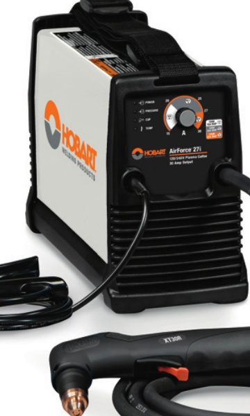
  • Hobart AirForce 27i Plasma Cutter Support: Parts Lookup and Buying Checks

    Hobart AirForce 27i Plasma Cutter Support

    If you maintain a Hobart AirForce 27i, the fastest way to avoid wrong-parts orders is to verify the machine identifier, torch family, power input, and air-side support items before you buy. The AirForce 27i support page from Weld Support Parts is set up as a lookup starting point for those checks. It lists the unit support page, the stock reference 500575, 120/240 V information, an XT30R replacement torch reference, consumables, MVP adapters, an air filter kit, cutting guides, and plasma support links.

    Key Takeaways

    • Use the support page to confirm the AirForce 27i parts path before ordering.
    • Verify torch model, consumable style, and power input at the machine nameplate and on the existing torch.
    • Air quality matters. Inspect the air filter path before troubleshooting arc problems.
    • Do not assume adapter or torch compatibility from appearance alone.
    • When details are unclear, mark them as Unknown (Verify) and confirm against the machine and torch labels.

    What the Support Page Is Useful For

    The Weld Support Parts AirForce 27i page is a parts lookup and support reference, not a substitute for the machine manual. It is useful when you need to match the cutter to support items such as the replacement torch, consumables, and air-side accessories. For this model, the page references stock 500575 and indicates 120/240 V support information. Treat those details as lookup cues and verify them on the machine before purchasing or installing parts.

    Open the Hobart AirForce 27i support page

    Buying Checks Before You Order Parts

    Before a maintenance buyer releases an order, do these checks in order:

    1. Check the machine data plate. Verify the exact model is Hobart AirForce 27i and confirm input power requirements. If the plate is unclear, record Unknown (Verify).
    2. Inspect the torch neck and handle label. Confirm whether the installed torch matches the XT30R family reference shown on the support page. Do not assume the torch is original.
    3. Pull the consumable set and compare wear patterns. Look at the nozzle, electrode, swirl ring, shield, and retaining parts. Replace only with the correct style for the torch in use.
    4. Check the air delivery path. Inspect filters, fittings, hoses, and water or oil contamination. A plasma cutter with poor air quality will often show unstable arc behavior.
    5. Confirm adapter needs. If the shop uses an alternate power plug or input arrangement, check whether the MVP adapter reference is relevant to your setup. Compatibility details not shown on the support page should stay Unknown (Verify).

    Troubleshooting and Support Checks

    Use these checks when the cutter starts to misbehave or when you are deciding which support part to buy.

    1) Torch and Consumable Check

    • Inspect: Look for heat damage, cracked cups, eroded electrodes, and loose retaining parts.
    • Verify: Match the torch consumables to the actual torch family on the machine. If the torch label is unreadable, mark the torch type Unknown (Verify) until confirmed.
    • Replace: Only the parts that are visibly worn or listed for the identified torch family.

    2) Air Supply Check

    • Inspect: Air filter kit condition, bowl contamination, hose leaks, and regulator settings.
    • Verify: The shop air is dry and clean enough for plasma use. If you see oil, water, or heavy debris, correct that before blaming the torch.
    • Check: Flow remains stable during trigger pull. A pressure drop can mimic a bad torch or bad consumable.

    3) Power and Input Check

    • Inspect: Input cord, plugs, adapters, and receptacle condition.
    • Verify: The machine is connected to the correct input class shown for the AirForce 27i support reference. If the exact electrical setup is not confirmed, note it Unknown (Verify).
    • Check: Any adapter or extension is rated and approved for the actual jobsite setup. Do not use an adapter just because the plug shape fits.

    4) Cut Quality Check

    • Inspect: Edge squareness, dross, and arc consistency.
    • Verify: The torch is held at a consistent standoff and travel speed.
    • Check: The cut guide or drag shield is appropriate for the work method you are using.

    WSP Lookup Page Notes

    The AirForce 27i support page is the correct first stop when you need a parts and support overview for this machine. It identifies the machine support page, stock 500575, the XT30R replacement torch reference, consumables, MVP adapters, air filter kit, cutting guides, and other plasma support links. Use those references to narrow the search, then confirm exact fitment against the machine and torch markings.

    Important: This page is a selection aid, not a blanket approval for every installed torch or accessory. If the part family is not confirmed from labels or existing component markings, the correct status is Unknown (Verify).

    Go to the Hobart AirForce 27i support page

    Practical Inspection Routine for Shops

    For routine maintenance, use a short inspection routine before each parts order or service ticket:

    • Record the machine model and serial tag information.
    • Compare torch markings to the support page reference.
    • Pull the last installed consumables and note wear pattern.
    • Inspect air filters and moisture traps.
    • Check the power plug, adapters, and cord strain relief.
    • Confirm any cutting guides or accessories are intended for the actual torch setup.

    Safety Notes

    • De-energize the machine before inspecting internal or electrical components.
    • Bleed pressure from the air system before opening filters or fittings.
    • Do not touch hot consumables immediately after cutting.
    • Use eye, hand, and body protection suitable for plasma cutting and grinding cleanup.
    • Do not bypass safety devices or use unverified adapters in an attempt to make a part fit.

    FAQ

    Is the XT30R replacement torch definitely the correct torch for every AirForce 27i?

    No. The support page references XT30R as a replacement torch reference, but you should still verify the torch family on the machine and existing torch. If the installed torch is not confirmed, mark it Unknown (Verify).

    Can I order consumables just by machine model?

    Not safely. Consumables must match the actual torch family and installed setup. Start with the AirForce 27i support page, then verify the torch label and worn parts before ordering.

    What should I check first if the cutter will not make a stable arc?

    Start with the consumables and the air supply. Inspect electrode and nozzle wear, then verify that air is clean, dry, and steady. If those checks are inconclusive, move to power input and torch condition.

    Are the MVP adapters universal?

    Do not assume that. The support page lists MVP adapters as a support reference, but any actual compatibility must be confirmed against the machine and power setup. If it is not confirmed, use Unknown (Verify).

    Sources Checked

    For maintenance teams, the key is simple: verify the machine, verify the torch, verify the air, then buy the parts that match what is actually installed. That is the cleanest way to support a Hobart AirForce 27i without creating avoidable returns or downtime.

    Disclosure: As an Amazon Associate, Weld Support Parts may earn from qualifying purchases.

    Related Weld Support Guides

  • ER308L MIG / GMAW Filler Metal: Filler Metal Finder Notes

    ER308L MIG / GMAW Filler Metal

    ER308L MIG / GMAW filler metal is a common starting point for welding 304-family stainless steel in fabrication and repair work. It is used widely, but it is not a default answer for every stainless joint. Selection still depends on the WPS, base metal grade, service conditions, joint design, corrosion exposure, and the manufacturer data sheet.

    Use the information below as a support guide only. Before ordering wire or welding production parts, verify the applicable procedure, code requirements, and base material identification.

    Key Takeaways

    • ER308L is commonly associated with 304 and 304L stainless applications.
    • It is a selection starting point, not proof of procedure approval.
    • Verify base metal, service environment, and required dilution control before use.
    • Check wire diameter, shielding gas, and feeder setup against the WPS and manufacturer sheet.
    • If the material is not confirmed, treat the selection as Unknown (Verify).

    Where ER308L Fits

    ER308L MIG / GMAW filler metal is generally discussed for stainless fabrication and repair where the base material is in the 304 family. That does not mean it is suitable for every stainless-to-stainless or stainless-to-carbon transition. Mixed-material joints, elevated corrosion duty, and code work can change the filler selection.

    For maintenance buyers and welders, the practical question is not “Is ER308L common?” The question is “Does the WPS and base metal confirm ER308L for this joint?” If that answer is not documented, stop and verify before welding.

    Troubleshooting and Support Checks

    1) Confirm the base metal

    • Check: Material tags, mill certs, heat numbers, and job documents.
    • Inspect: Whether the part is 304, 304L, or another stainless grade.
    • Verify: If the grade is not confirmed, mark it Unknown (Verify) and do not assume ER308L is correct.

    2) Check the WPS

    • Check: Procedure number, filler classification, wire diameter, transfer mode, shielding gas, and pass sequence.
    • Inspect: Whether the procedure allows ER308L for the joint and position.
    • Verify: Code jobs may require a specific filler or additional controls beyond what is typical in general fabrication.

    3) Match service conditions

    • Check: Exposure to chemicals, moisture, heat, washdown, or food-contact requirements.
    • Inspect: Whether the service environment changes corrosion performance expectations.
    • Verify: If service conditions are unclear, treat them as Unknown (Verify) and review the design documents.

    4) Inspect the wire and feed path

    • Check: Spool condition, storage condition, and packaging integrity.
    • Inspect: Drive rolls, liner, contact tip, and torch cable for contamination or excess drag.
    • Verify: Feed issues are often mechanical, not filler-related. Correct the feeder setup before changing wire type.

    5) Review shielding gas and parameters

    • Check: Gas mix, flow rate, voltage, and wire feed speed against the procedure.
    • Inspect: For signs of excessive spatter, lack of fusion, or poor wetting.
    • Verify: Parameter windows vary by wire diameter and transfer mode. Do not guess settings.

    Filler Metal Finder Notes

    Use the ER308L filler metal page as a selection starting point, not as a guaranteed procedure approval. It is intended to help narrow the filler choice for stainless MIG / GMAW work, but the final decision still belongs to the WPS, code requirements, and base metal identification.

    Review the provided page here: ER308L MIG / GMAW Filler Metal

    Use the filler metal finder here when you need to compare support options before ordering: Filler Metal Finder

    What to confirm while using the page:

    • Classification: ER308L
    • Process: MIG / GMAW
    • Base material: 304 and 304L stainless
    • Required wire diameter: Unknown (Verify)
    • Shielding gas: Unknown (Verify)
    • Manufacturer availability: Unknown (Verify)

    If the job calls for ER308LSi, ER309L, or another stainless filler, do not substitute based only on similarity. Confirm the procedure and the engineering requirement first.

    Practical Ordering Notes

    Before purchase, verify the exact wire diameter needed for the gun setup and deposition rate. Common diameter options may be listed by suppliers, but the acceptable size for your job is determined by the procedure and equipment setup. If the diameter is not stated in your documents, treat it as Unknown (Verify).

    Also confirm spool size, packaging, and storage plan before placing the order. Stainless wire contamination from poor handling can create problems during feeding and weld quality. Keep wire sealed until use and store it in a clean, dry area.

    Safety Notes

    • Use required PPE for stainless welding, including eye, face, hand, and skin protection.
    • Provide ventilation or fume extraction appropriate for the work area.
    • Do not weld on unidentified material without a documented verification step.
    • Follow site hot-work rules, purge requirements, and contamination control procedures.
    • For regulated work, follow the approved WPS and the responsible engineer’s instructions.

    FAQ

    Is ER308L always correct for 304 stainless?

    No. It is commonly used for 304-family stainless, but you still need to verify the WPS, joint design, and service conditions. If the grade is not confirmed, the answer is Unknown (Verify).

    Can ER308L be used without checking the procedure?

    No. Do not treat common use as approval. The WPS or governing document controls the filler selection.

    What should I check first before ordering ER308L wire?

    Check the base metal grade, required wire diameter, shielding gas, and the procedure approval. If any item is missing, verify it before ordering.

    Is the filler metal finder a guarantee that ER308L will work?

    No. The finder is a support tool and selection starting point. It does not replace the WPS, code requirements, or manufacturer data sheet.

    Sources Checked

    Final note: confirm the WPS, code requirements, base metal grade, service conditions, and manufacturer data sheet before welding or placing a production order.

    Disclosure: As an Amazon Associate, Weld Support Parts may earn from qualifying purchases.

  • 000-069 Miller Style M-Series Contact Tip .045 – Arc Weld by Masterweld Pack of (25): Replacement Part Breakdown

    Choosing the right contact tip is basic maintenance, but it affects wire feed stability, arc consistency, and how often you have to stop and correct a problem. This guide covers the 000-069 Miller Style M-Series Contact Tip .045 – Arc Weld by Masterweld Pack of (25) as a replacement part item for MIG welding support workflows. The key point is simple: treat this as a consumable fitment decision, not a guess. If the gun, neck, diffuser, or thread pattern is not verified, do not assume interchangeability.

    Key Takeaways

    • A .045 contact tip must match the wire size you are actually running.
    • “Miller Style M-Series” is a fitment description, not a guarantee for every Miller gun or every third-party gun labeled similar.
    • Contact tips wear from heat, spatter, and wire friction. A worn tip can look minor and still cause feed issues.
    • If fit, thread, or gun series is uncertain, mark it Unknown (Verify) and inspect before installation.

    What this part is used for

    A contact tip transfers welding current to the wire and helps guide that wire into the puddle. In practical terms, it is a wear part that sits at the front of the gun and takes abuse from heat and spatter. When it is correct and clean, wire feed is smoother. When it is damaged or the bore is oversized, undersized, or contaminated, you may see erratic feed, burnback, or a wandering arc.

    The product name indicates .045 diameter and a Miller style M-Series fitment. That is the starting point for selection only. Verify the gun model, tip threading, diffuser style, and wire diameter before using it in production.

    Check, inspect, verify before installation

    1. Check the wire size. Confirm the wire being used is .045. Do not install a .045 tip on a different wire size without a documented procedure.
    2. Inspect the thread and shoulder. Compare the new tip to the removed tip. Verify thread pattern, length, and seat profile. If anything does not match, stop and label it Unknown (Verify).
    3. Verify gun compatibility. Confirm the gun and front-end parts are truly Miller M-Series style. “Style” language can be broad. Do not assume cross-compatibility.
    4. Check for spatter damage. If the old tip has heavy spatter buildup, inspect the diffuser and nozzle as well. A bad tip is often only one part of a larger front-end issue.
    5. Clean the mounting surface. Wipe the diffuser threads and seating area before installing the replacement tip.

    Troubleshooting and support

    If the wire feed becomes inconsistent after a tip change, work through the front-end items in order.

    • Check: Is the wire size actually .045? Mixed wire and tip sizes create drag or chatter.
    • Inspect: Is the tip bore worn, burned, or partially blocked with spatter?
    • Verify: Is the tip fully seated and tightened correctly without over-torquing?
    • Check: Is the liner condition acceptable, or is the problem upstream in the gun cable?
    • Inspect: Are the drive rolls set correctly for the wire type and diameter?
    • Verify: Is the nozzle clear enough that spatter is not overheating the tip?

    Common symptoms tied to a contact tip problem include burnback, intermittent arc starts, birdnesting caused by feed resistance, and a rough or unstable arc. Do not replace one front-end part and assume the rest of the system is good. Support teams should inspect the tip, diffuser, nozzle, liner, drive rolls, and gun cable as a set.

    Product and parts notes

    This item is listed as an Arc Weld by Masterweld replacement part pack of 25 under ASIN B07Y41NL57. That tells you the part is being marketed as a consumable replacement item, but it does not replace verification of fit. Use the product listing only as the source of the provided item name. Do not assume the part is approved for every Miller or Miller-style setup.

    For purchasing workflows, the important questions are practical:

    • Does the gun front end take a Miller-style M-Series tip?
    • Is the current wire diameter .045?
    • Is the replacement tip shape and thread the same as the removed tip?
    • Has the surrounding front-end hardware been inspected for wear?

    If any answer is uncertain, classify the fit as Unknown (Verify) and confirm against the actual gun and front-end parts in the shop.

    How maintenance buyers should evaluate the part

    Maintenance buyers usually need consistency, not just a part number. This means confirming the existing gun fleet, wire sizes in use, and whether a single front-end standard is being held across multiple machines. If the shop runs mixed guns or mixed consumables, keep replacement tips separated by verified fitment, not by appearance alone.

    When a tip pack is received, log the following before issuing it:

    • Gun model verified against shop equipment
    • Wire diameter verified as .045
    • Thread/seat style matched to the removed part
    • Front-end wear condition recorded

    This reduces false troubleshooting. Many feed complaints are not caused by the tip alone. They are caused by a worn liner, wrong drive roll groove, poor cable routing, or a dirty gun neck.

    Safety notes

    • Lock out the welding power source before handling front-end consumables during maintenance.
    • Allow the gun and tip to cool before removal. Contact tips can retain heat long after welding stops.
    • Wear gloves when removing spatter-damaged parts. Sharp slag and hot metal can cut or burn.
    • Do not force a tip onto a mismatched diffuser or thread pattern.
    • Use only verified consumables in production work. If fitment is uncertain, stop and inspect.

    FAQ

    Q1: Is this contact tip automatically correct for every Miller MIG gun?
    No. The listing says Miller style M-Series, but that is not a blanket compatibility claim. Verify the actual gun model and front-end parts.

    Q2: Why does a worn contact tip cause wire feed trouble?
    Wear enlarges the bore and changes wire guidance. That can produce unstable current transfer, burnback, or erratic feed.

    Q3: Can I use this tip if my wire is not .045?
    No. The listed size is .045. Using another wire size without verification can create feed problems and poor arc performance.

    Q4: What should I check if a new tip does not seat correctly?
    Check the thread pattern, diffuser fit, seating surface, and the removed tip as a reference. If the match is uncertain, mark it Unknown (Verify).

    Sources Checked

    Note: No WSP lookup page or filler metal finder page was provided for this draft, so no selection-link section was included.

    Matched Replacement Option

    No products found.

    Disclosure: As an Amazon Associate, Weld Support Parts may earn from qualifying purchases.

    Related Weld Support Guides

  • Washington Alloy 9018-M 10lbs Welding Stick Electrode (3/32″): Product Breakdown

    Washington Alloy 9018-M 10lbs Welding Stick Electrode (3/32")
    “>Washington Alloy 9018-M 10lbs Welding Stick Electrode (3/32")

    Washington Alloy 9018-M 10lbs Welding Stick Electrode (3/32″) is a low-hydrogen stick electrode intended for demanding structural and repair work where weld quality and toughness matter. The product description identifies it as an all-position, iron-powder electrode with manganese, molybdenum, and nickel, and notes it is aimed at low alloy, high tensile, quenched, and tempered steels such as T1, HY80, and HY90. That puts it in a class of consumables that buyers often choose for stronger base metals, but the final selection still depends on the job procedure, material condition, and code requirements.

    This article breaks down what the product description tells you, what you should verify before use, and how to support the electrode in the shop. It is a buyer guide, not a procedure approval. If the job is code work, match the electrode to the WPS, base metal, joint design, and preheat/postheat requirements.

    Key Takeaways

    What the Product Breakdown Means

    The term low-hydrogen matters because hydrogen control is a common concern on higher-strength steels and restrained joints. In practical terms, the electrode should be stored and handled to limit moisture pickup. The listing also calls it iron-powder. That usually signals higher deposition efficiency than a plain general-purpose rod, but exact deposition behavior for this specific product is Unknown (Verify) unless you are working from the manufacturer data sheet or a qualified procedure.

    The alloy content listed in the product summary suggests the rod is intended to support strength and toughness requirements. That does not mean it is the correct filler for every high-strength steel. Verify the base metal specification, thickness, restraint, service temperature, and any code or customer requirements before issuing it to production.

    Practical Check / Inspect / Verify Steps

    Troubleshooting Support for Shop Use

    If the arc is unstable, the first checks should be basic. Inspect the electrode for moisture damage, verify the machine output, and confirm the work lead and stinger connections. If slag is difficult to remove, check travel speed and bead shape against the procedure. If cracking appears, stop and verify preheat, interpass control, restraint, and hydrogen management before continuing.

    For operators using a stinger and holder, support gear matters. A worn holder jaw, loose cable connection, or poor ground can create heat loss and inconsistent arc behavior. If you need a refresher on holder setup and stick welding handling, see Welding Electrode Holder: Stinger Guide & Stick Welding Tips and Welding Electrode Holder: Choose the Best for Stick Welding.

    Product / Parts Section

    The product referenced here is Washington Alloy 9018-M 10lbs Welding Stick Electrode (3/32″). The provided source description indicates the rod is designed for low alloy, high tensile, quenched, and tempered steels and highlights impact performance and X-ray quality deposits. No further technical specifications were provided in the source set, so current diameter, length, current range, recovery rate, and storage limits are Unknown (Verify).

    Use this product as a support item when your procedure and material call for this family of electrode. It is not a universal replacement for general-purpose rods. If you need a different structural stick option for comparison, a related support article on a 7014 electrode is available here: Washington Alloy 7014 Stick Electrode – Smooth Welding with High Deposition. That article is a selection reference, not a procedure approval.

    Support Buying Notes

    For maintenance buyers, the key question is not only whether the electrode is available, but whether it matches the weld requirement. Before buying, verify the joint type, service condition, and whether the job uses a qualified WPS. If purchasing for stock, label it by electrode family and keep usage notes by job type so the next shift does not have to guess. If the work mixes general fabrication and high-strength repair, separate the stock clearly to avoid mix-ups.

    If you are also reviewing related equipment, the stinger and holder should be matched to expected duty and cable condition. A good electrode will not compensate for poor current transfer or damaged leads.

    Safety Notes

    FAQ

    Is Washington Alloy 9018-M the same as every other 9018 rod?
    No. The designation suggests a similar electrode family, but you should not assume identical performance, polarity, or settings. Verify against the manufacturer data and the job procedure.

    Can this rod be used on any high-strength steel?
    No. The listing names certain high-strength and quenched-and-tempered steels, but actual suitability depends on the base metal, service conditions, and procedure approval. Verify before use.

    Does the listing guarantee X-ray quality welds?
    No guarantee can be assumed from a product summary alone. The source says the deposits are X-ray quality, but the final result depends on fit-up, technique, cleanliness, parameters, and inspection requirements.

    What should I verify before putting it into production?
    Check the WPS, base metal spec, preheat needs, storage condition, and current settings. Also verify that the joint prep and operator qualifications match the task.

    Sources Checked

    Note: No WSP lookup page or filler metal finder page was provided for this draft. Technical details not present in the supplied sources are marked Unknown (Verify).

    Related Arc Weld Part

    Washington Alloy 9018-M 10lbs Welding Stick Electrode (3/32")

    Washington Alloy 9018-M 10lbs Welding Stick Electrode (3/32")

    9018M is an all-position, low-hydrogen, iron-powder electrode containing manganese, molybdenum, and nickel. 9018M is designed for welding low alloy, high tensile, quenched, and tempered steels such as T1, HY80, and HY90. Weld deposits have excellent impact properties and are X-ray quality. PREHEATING AND POSTHEATING Depending upon the thickness and hardening characteristics of the workpiece, preheating at a temper…

    View at Arc Weld Store

    Related Weld Support Guides

  • Listen with Audible