Category: Gas Apparatus Support
Cutting Torches, Regulators, parts breakdowns, and accessories
-
Miller 296102, Field Kit, Regulator Board Ground Tb Gas: Product Breakdown
“>
Miller 296102 is a genuine field kit for the regulator board and ground-related assembly used on Trailblazer gas units. For maintenance buyers and welding support teams, the main value of this part is straightforward: it is an OEM replacement intended to correct electrical or grounding issues without guessing at fitment. When the original regulator board/ground assembly is failing, a correct replacement helps restore stable generator output and weld performance.
This is not a generic repair item. It is a manufacturer-issued replacement that supersedes Miller part 273988. That matters because field repairs on engine-driven welders often fail when the replacement is close but not exact. If you are working from a unit serial number, service record, or teardown note, verify the current OEM part callout before ordering.
Key Takeaways
- Miller 296102 is an OEM field kit for a Trailblazer gas regulator board/ground application.
- It supersedes Miller part 273988.
- Use it when the original regulator board/ground assembly is suspected in unstable output, not as a guess-and-check part swap.
- Fitment must be verified against the machine model and parts breakdown before installation.
- If the fault is not electrical, the kit will not correct fuel, engine, or load-side problems.
What this part is used for
The available product information indicates this kit supports restoration of stable power generation and weld output on Trailblazer gas machines. In practice, the board and ground path are part of the machine’s electrical control and reference system. When either is compromised, symptoms can include erratic weld output, unstable generator behavior, or intermittent performance. Exact failure mode depends on the machine condition. Unknown (Verify) if your unit has additional damage, previous repairs, or modified wiring.
Check, inspect, verify before ordering
Use the following sequence before you commit to the part.
- Check the machine identity. Verify the Trailblazer gas model and record the serial number.
- Inspect the existing board/ground area. Look for heat damage, loose terminals, corrosion, vibration wear, or signs of a prior repair.
- Verify the parts breakdown. Confirm that Miller 296102 is the current OEM callout and that it supersedes 273988 for your exact unit.
- Test symptoms carefully. If output is unstable, rule out battery condition, cabling, grounding, engine speed issues, and damaged connectors before replacing the assembly.
- Document before removal. Photograph wire routing, terminal positions, and ground locations so reassembly matches the original configuration.
Troubleshooting support path
If the machine is still producing inconsistent power, isolate the issue in layers.
- Power and charging checks: Verify battery condition and charging system status. A weak electrical supply can look like board failure.
- Ground path inspection: Inspect the machine ground path end to end. Clean contact surfaces if contamination is present, but do not remove material unless the service procedure allows it.
- Connector verification: Check for bent pins, loose spades, burned insulation, or evidence of arcing.
- Load-side review: Confirm the reported problem is not caused by accessories, cables, or connected equipment.
- Board replacement decision: Replace the regulator board/ground assembly only after the surrounding circuit checks do not explain the fault.
If you do not have a current parts listing for the exact unit, Unknown (Verify) whether a serial-specific revision applies. Do not assume that a Trailblazer gas machine uses the same board across all builds.
Product and parts notes
Miller 296102 is listed as a field kit, which signals a repair-oriented package rather than a broad service assembly. For buyers, that means the part should be treated as a targeted OEM solution for the board/ground area. The source information does not provide full kit contents. Unknown (Verify) what hardware, leads, or instructions are included. Confirm packaging against your receiving inspection before sending the job to the floor.
Because this is an electrical repair component, do not mix it with non-OEM substitutes unless the service documentation specifically allows it. Incorrect grounding or board substitution can create repeat failures that are harder to diagnose than the original problem.
How to verify correct fitment on the job
- Match the machine model name and type first.
- Match the serial number to the parts breakdown if available.
- Confirm the old number 273988 is actually the superseded reference for your machine.
- Inspect the mounting points and harness layout before removing the old assembly.
- After installation, test weld output and generator behavior under normal operating conditions.
If the machine still behaves unpredictably after replacement, revisit the wiring harness, connectors, and engine-side controls. A board can be correct and still not solve a system-level fault.
Safety notes
- Lock out the machine before opening electrical compartments.
- Discharge stored energy according to the service procedure.
- Use insulated tools when working around live circuits.
- Do not bypass protective devices to force a test run.
- If you find burned insulation, melted connectors, or repeated arcing, stop and investigate the root cause before installing a new part.
FAQ
Is Miller 296102 an OEM replacement?
Yes. The provided product description identifies it as a genuine manufacturer-issued replacement.What does it replace?
It supersedes Miller part 273988, based on the source information provided.Will this part fix any Trailblazer gas output problem?
No. It addresses the regulator board/ground area. Fuel, engine speed, wiring, or load problems can create similar symptoms and should be checked first.Do I need the exact serial number to order it?
You should verify model and serial-specific parts data before ordering. Unknown (Verify) if a specific revision applies to your machine.Sources Checked
- ArcWeld product page: Miller 296102, Field Kit, Regulator Board Ground Tb Gas
- Provided product short description and source idea
Related Arc Weld Part
Miller 296102, Field Kit, Regulator Board Ground Tb Gas
Miller 296102 is a genuine Trailblazer (gas) regulator board ground field kit designed to restore stable power generation and weld output when the original regulator board/ground assembly is failing. This kit is the manufacturer-issued replacement that supersedes Miller part 273988, making it the correct choice when you need an OEM-fit electrical repair instead of risking aftermarket fitment or incorrect electrica…
View at Arc Weld Store
GOSS HEF-6, Vapor Propane Gas Hose, 1/4 in Hose ID, 6 ft: Product Breakdown
“>
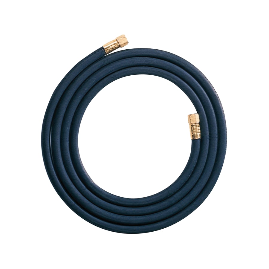
The GOSS HEF-6 is a vapor propane gas hose assembly for LP gas service. For buyers, maintenance teams, and field users, the main value is straightforward: a flexible connection between a regulator and a torch or appliance where vapor propane delivery is required. The listed hose size is 1/4 in. inside diameter and the length is 6 ft. That gives enough reach for common shop setups without adding much loose hose to manage.
This article focuses on practical use, inspection points, and support checks. It does not assume application approval beyond the product description. If your setup has a specific burner, torch, or appliance requirement, verify the hose rating against the equipment manual before use.
Key Takeaways
- Designed for vapor propane gas service.
- Hose size is 1/4 in. ID; length is 6 ft.
- Best treated as a connection component, not a universal hose for all LP tasks.
- Fit, pressure rating, fittings, and service limits must be verified against your system.
- Inspect for wear, cracking, loose ends, leaks, and heat damage before each use.
What the GOSS HEF-6 is used for
Based on the product listing, the GOSS HEF-6 is intended for vapor propane gas service. In practical terms, that means it is used where LP vapor needs to move from one part of a gas system to another through a flexible hose. Common use cases in shops and maintenance environments include torch setups and appliance connections, but the exact equipment match is not guaranteed by the listing. Verify the end connections, hose rating, and service requirements before installation.
When assessing this hose for purchasing or replacement, check four items first: gas type, connection type, hose length, and the physical routing path. A hose that is too long can create handling issues. A hose that is too short can stress fittings or force awkward bends. A 6 ft hose often fits compact setups, but your actual reach requirement depends on cylinder placement, regulator location, and work cell layout.
Check, inspect, verify
Check: Confirm the service is vapor propane gas, not another fuel or industrial gas. Confirm the hose length will reach without tension and without being left in a traffic path.
Inspect: Look along the full hose body for abrasion, cracking, hard spots, cuts, soft spots, discoloration from heat, or flattening. Inspect the ends for damaged threads, loose ferrules, bent fittings, or signs of seepage.
Verify: Match the hose ends to the regulator and torch or appliance connections. Verify any pressure, temperature, and hose construction requirements in the equipment documentation. If the exact pressure rating is not available from the listing, treat it as Unknown (Verify) until confirmed by the manufacturer or seller documentation.
Check: Make sure the hose path will not rest against sharp edges, hot surfaces, moving parts, or welding slag zones.
Inspect: Confirm the hose has not been twisted during installation. Twisting can shorten service life and make leaks harder to spot.
Verify: After connection, perform a leak check using the method approved for your site. If the site standard is not available, use the procedure required by your safety program. Do not use an open flame to check for leaks.
Troubleshooting and support points
If gas flow seems inconsistent, do not assume the hose is the only cause. Start with the system and work outward.
Issue: weak or unstable flame
Check the regulator setting, cylinder supply status, and downstream equipment first. Inspect the hose for kinks or internal collapse. Verify the hose is not undersized for the application. If hose size or internal condition is uncertain, treat it as Unknown (Verify) until inspected by a qualified person.
Issue: smell of gas or suspected leak
Stop work. Close the supply if it can be done safely. Inspect both ends of the hose and all threaded or connected interfaces. Verify that the hose is fully seated and secured per the equipment design. If the leak source is not obvious, remove the hose from service until the source is found.
Issue: hose damage near the ends
Check whether the hose is being bent too tightly near the fittings. Re-route the line to reduce strain. If the ends show damage, replace the hose rather than trying to repair it in the field unless the manufacturer specifically allows service repair.
Issue: hose routed through a work area
Inspect the route for pinch points, carts, doors, and foot traffic. Verify that the hose is protected from wear and does not create a trip hazard. Use supports or routing changes as needed.
Product and parts considerations
The available product information identifies the hose as a complete assembly, but it does not provide enough technical detail to confirm every fitting style, pressure class, or construction layer. Those details should be treated as Unknown (Verify) unless confirmed in the manufacturer documentation.
For buyers and maintenance teams, the practical decision points are:
- Does the hose connect to your regulator without adapters that create extra leak points?
- Does the hose length fit the actual installation path?
- Is the hose intended for vapor propane service in your use case?
- Is the physical routing protected from heat, abrasion, and crushing?
If you are replacing an existing hose, compare the old hose end fittings and marked service information against the new assembly before installation. If the old hose is unreadable or damaged, do not use it as the only reference.
Safety notes
- Use only in the service intended by the product listing.
- Keep the hose away from flame, hot metal, and sharp edges.
- Do not use a damaged, cracked, or leaking hose.
- Do not use open flame leak checks.
- Do not force incompatible fittings together.
- If the hose condition or rating cannot be confirmed, remove it from service and verify with the supplier or manufacturer.
FAQ
Is the GOSS HEF-6 a universal propane hose?
No. It is listed for vapor propane gas service, but universal use should not be assumed. Verify the hose ends, pressure needs, and equipment requirements before purchase or installation.
Can I use this hose for any torch setup?
Not without verification. Torch systems vary by fitting type, gas service, and required hose rating. Check the torch and regulator documentation first.
What should I inspect before each use?
Check the full hose length for abrasion, cracks, cuts, heat damage, kinks, and loose fittings. Verify that routing is clear of traffic and hot surfaces.
What if I cannot confirm the hose pressure rating?
Treat it as Unknown (Verify). Do not put it into service until the rating is confirmed from manufacturer or seller documentation.
Sources Checked
- ArcWeld product listing: GOSS HEF-6, Vapor Propane Gas Hose, 1/4 in Hose ID, 6 ft
- Provided product description and shop-use context in the task brief
For this draft, no WSP lookup page, filler metal finder page, internal links, or additional compatibility sources were provided. As a result, product-specific technical details beyond the listing should be treated as Unknown (Verify).
Related Arc Weld Part
GOSS HEF-6, Vapor Propane Gas Hose, 1/4 in Hose ID, 6 ft
Built for vapor propane gas service, the GOSS HEF-6 is a durable, flexible hose assembly designed for reliable connections between your regulator and torch or appliance. The 1/4 in. inside diameter supports consistent gas flow for common shop and field setups, while the 6 ft length gives you practical reach without excessive slack. Key Features Application: Vapor propane gas (LP) service Hose size: 1/4 in. ID Leng…
View at Arc Weld Store