If a Lincoln Magnum MIG gun trigger sticks, stays partly engaged, feeds wire after release, double-clicks, or only works when squeezed hard, do not assume the whole welder is bad. Most trigger problems are in the gun handle, trigger switch, trigger leads, strain relief, connector seating, or contamination inside the handle. The safe first step is to stop welding, disconnect input power, remove the gun from service, and verify whether the trigger is mechanically sticking or electrically staying closed.
A stuck trigger can keep the wire drive, output, or gas circuit active depending on the feeder and machine. Common causes include spatter dust in the handle, a cracked trigger lever, worn trigger return spring, failed microswitch, pinched trigger wires, damaged control leads at the cable strain relief, loose gun connector, incorrect trigger plug seating, or a feeder-side trigger/interlock problem. For related MIG gun identification and wire-feed symptoms, see how to identify your MIG gun, MIG wire feed slipping troubleshooting, and MIG burnback troubleshooting.
Common Symptoms
Trigger does not return fully after release.
Wire keeps feeding after the operator lets go of the trigger.
Gun works only when the trigger is pulled at a certain angle.
Trigger feels gritty, sticky, loose, or cracked.
Wire feed starts and stops when the cable is flexed near the handle.
Gas solenoid clicks inconsistently when the trigger is pulled.
Machine output or wire feed stays active until the gun is unplugged.
Trigger works cold but sticks after the handle gets hot.
Trigger lever moves normally, but the switch does not click consistently.
Likely Causes
Cause
What It Does
Quick Check
Spatter dust or shop debris inside handle
Prevents full trigger return
Trigger feels gritty or slow
Cracked trigger lever
Lever binds in the handle or fails to press switch squarely
Inspect pivot and trigger face
Weak or missing return spring
Trigger does not snap back
Release trigger and watch return travel
Failed trigger switch
Electrical contacts stay open, closed, or intermittent
Continuity test switch while actuating
Pinched trigger leads
Shorts trigger circuit or cuts out when handle moves
Inspect wires inside handle and strain relief
Broken control lead near cable strain relief
Trigger works only when cable is bent a certain way
Flex cable while testing continuity
Loose gun connector or trigger plug
Machine does not read trigger consistently
Reseat gun and trigger connector fully
Trigger interlock or feeder-side fault
Wire feeds without normal trigger command
Remove gun; if fault remains, inspect feeder/machine
Fast Safety Check
Stop welding immediately if the wire keeps feeding after trigger release.
Point the gun away from people and the work area.
Turn the welder off and disconnect input power before opening the gun handle.
Clip the wire at the contact tip so the gun cannot unexpectedly feed into a part or person.
Unplug the gun trigger connector or remove the gun from the feeder where applicable.
Do not continue welding with a sticking trigger. A stuck trigger is a control fault, not an adjustment issue.
Inspection Steps
Trigger lever: Look for cracks, melted edges, worn pivot points, missing spring action, or a lever rubbing the handle shell.
Handle shell: Check for crushed plastic, missing screws, stripped screw posts, or handle halves pinching the trigger.
Switch body: Verify the switch clicks cleanly and returns every time. A weak or inconsistent click usually means replacement.
Trigger leads: Inspect for broken insulation, splices, crushed wires, loose terminals, or wires routed under the trigger lever.
Strain relief: Flex the cable near the handle. If the trigger signal cuts in or out, suspect broken conductors inside the cable.
Gun connector: Confirm the gun is fully seated in the feeder and the trigger plug is fully engaged where the gun uses a separate trigger plug.
Feeder controls: Check for 2T/4T trigger mode, trigger interlock, spool gun selector, or machine-side control settings before condemning the gun.
Test Procedures
Mechanical return test: With the machine off, pull and release the trigger ten times. It should return sharply without dragging.
Handle-open inspection: Open the handle only after power is disconnected. Look for debris, melted plastic, pinched wires, and broken switch mounting tabs.
Continuity test: Test the trigger switch leads with a meter. The circuit should change state only when the trigger is pulled.
Cable-flex test: While watching the meter, flex the cable near the handle and rear connector. Continuity should not change unless the trigger is pulled.
Gun-removal test: If the machine feeds or stays energized with the gun removed, the problem is not the gun trigger. Move to feeder or machine troubleshooting.
Connector test: Reseat the gun and trigger plug, then test again. A loose connector can mimic a failing switch.
Root Cause Analysis
A Magnum gun trigger is a low-voltage control point that tells the feeder or machine to start the wire drive and related welding functions. When the trigger lever sticks mechanically, the switch may remain pressed. When the switch contacts fail electrically, the trigger can act stuck even if the lever moves freely. When trigger leads short together inside the handle or cable, the machine may see a constant trigger command.
Heat and contamination make the problem worse. A gun used around heavy spatter, grinding dust, anti-spatter residue, and overhead welding can collect debris inside the handle. If the cable has been pulled around sharp corners, the trigger conductors can break or short near the strain relief. Lincoln Magnum and Magnum PRO guns are repairable in many cases, but the correct trigger or handle assembly depends on the exact gun family.
Compatibility Notes
Do not order a Lincoln Magnum trigger switch by machine model alone. Verify the actual gun installed on the machine. POWER MIG, LN feeders, portable wire feeders, and replacement guns may use Magnum 100L, Magnum PRO 100L, Magnum 250L, Magnum PRO 250L, Magnum 300/400, Magnum PRO Curve, Magnum PRO HDE, spool guns, or older gun assemblies. Earlier machines may have shipped with different gun families than later replacements.
Also confirm whether the problem is the trigger lever, the switch, the housing assembly, the cable control leads, the rear connector, or the machine-side trigger circuit. Some trigger-related parts are switch-only repairs. Others are trigger-and-housing assemblies or locking trigger kits. If the exact gun name, gun part number, cable length, and connector style cannot be confirmed, mark the part as Unknown (Verify) before ordering.
What To Verify Before Ordering
Lincoln machine model and machine code number.
Installed gun name, not just the welder name.
Gun part number, cable length, and amperage class.
Whether the gun is Magnum, Magnum PRO, Magnum PRO Curve, Magnum PRO HDE, spool gun, or fume gun.
Trigger style: standard trigger, locking trigger, spool gun trigger, or trigger/housing assembly.
Trigger connector type at the machine or feeder.
Condition of handle shell, switch, trigger leads, and strain relief.
Whether the fault disappears when the gun is unplugged from the machine.
Common Wrong-Part Mistakes
Ordering a trigger switch for the welder model instead of identifying the gun.
Assuming Magnum 100L, Magnum PRO 100L, and Magnum PRO 250L use the same trigger repair part.
Replacing the switch when the real failure is a broken trigger lead at the strain relief.
Replacing the full gun when the handle switch assembly is serviceable.
Ignoring machine trigger interlock or 4T settings that can look like a stuck trigger.
Using cleaner or lubricant that attacks plastic handle parts or leaves conductive residue.
Field Fix vs Proper Fix
Problem
Field Fix
Proper Fix
Debris under trigger
Blow out handle area with dry air after power is disconnected
Open handle, clean, inspect trigger, and replace damaged parts
Trigger lever binds
Stop using the gun
Replace trigger lever or trigger/housing assembly
Switch contacts intermittent
Reseat connectors and test
Replace correct trigger switch or assembly
Wire feeds when cable is flexed
Keep cable still only long enough to diagnose
Repair or replace damaged control leads/cable assembly
Wire feeds with gun removed
Do not reconnect gun until isolated
Troubleshoot feeder, trigger interlock, relay, board, or machine-side circuit
Related Failure Paths
Wire feed will not start: Trigger switch open, broken trigger lead, loose plug, or machine-side trigger circuit fault.
Wire feed will not stop: Trigger switch stuck closed, shorted trigger leads, interlock setting, or feeder-side stuck control circuit.
Burnback: A trigger that cuts in and out can interrupt feed while the arc is still hot.
Gas flow issues: If the gas solenoid does not actuate when the trigger is pulled, the gun cable assembly or machine circuit must be separated by testing.
Arc instability: Intermittent trigger signal can look like a wire-feed or contact-tip problem.
Safety Notes
Disconnect input power before opening the gun handle or testing trigger wiring.
Do not weld with a trigger that sticks closed or feeds wire after release.
Keep hands away from drive rolls and the contact tip during trigger testing.
Do not bypass the trigger switch to keep working. That removes operator control.
Use dry gloves and eye protection when handling the gun and clipped wire.
If the fault remains with the gun unplugged, use a qualified Lincoln service facility or technician.
Sources Checked
Sources checked include Lincoln Magnum and Magnum PRO gun manuals, Lincoln POWER MIG troubleshooting references, the Lincoln 2024 expendable parts guide, and related Weld Support Parts MIG gun troubleshooting articles. Final trigger replacement must be verified by exact gun family, gun part number, handle style, trigger connector, cable condition, and machine-side trigger behavior.
MIG nozzle spatter buildup is not just a cleaning issue. When spatter packs inside the nozzle, bridges toward the contact tip, or blocks the diffuser ports, shielding gas flow becomes restricted or turbulent. The weld can then show porosity, black soot, erratic arc starts, excess spatter, contact tip overheating, and repeated burnback even when the gas cylinder and regulator look normal.
The fast fix is to shut the machine off, let the gun cool, remove the nozzle, clean or replace the nozzle, inspect the diffuser holes, and replace the contact tip if it is worn, arc-marked, or spatter-packed. Do not compensate for a blocked nozzle by raising gas flow first. High gas flow can also create turbulence. Clean the front end, verify nozzle bore and tip recess, then test weld on clean material. For related front-end failures, see MIG diffuser clogging symptoms, MIG porosity troubleshooting, and MIG wire burnback into the contact tip.
Common Symptoms
Pinholes, wormholes, or scattered porosity appear after several welds.
Nozzle bore is packed with BB-like spatter or slag-colored deposits.
Gas sounds normal at the regulator, but the weld acts unshielded.
Arc starts rough, pops, or wanders before stabilizing.
Spatter increases even though settings have not changed.
Contact tip turns blue, burns back, or fuses wire more often.
Nozzle sticks to the work or fills faster in corners and short stickout work.
Weld bead has black soot or an oxidized surface around the toes.
Likely Causes
Cause
What It Does
Quick Check
Spatter-packed nozzle
Restricts or redirects shielding gas
Remove nozzle and inspect bore with light
Blocked diffuser ports
Creates uneven gas flow around the tip
Look for plugged side holes behind the nozzle
Nozzle too small for application
Fills quickly and limits gas envelope
Compare bore size to wire size, amperage, and joint access
Tip recess or stickout wrong
Changes gas coverage and arc behavior
Verify contact tip position for the gun/nozzle style
Voltage/WFS imbalance
Creates excessive spatter at the arc
Adjust one variable at a time after cleaning front end
Too short stickout
Runs nozzle too close and overheats the front end
Hold a consistent contact-tip-to-work distance
Too much anti-spatter or nozzle dip
Can contaminate gas path or collect debris
Use a light coating only on approved areas
Damaged nozzle insulation
Can cause arcing to the nozzle
Replace nozzles with cracked or burned insulation
Inspection Steps
Turn off the welder and let the gun front end cool.
Remove the nozzle. Do not twist against a hot, seized nozzle with bare hands.
Look inside the nozzle bore. Replace it if spatter is fused, the bore is distorted, or the insulation is damaged.
Inspect the contact tip. Replace it if the bore is oval, rough, arc-marked, or partially plugged.
Inspect the diffuser. Gas holes must be open and threads must hold the tip square.
Check whether spatter is bridging between the nozzle, tip, and diffuser.
Confirm the nozzle bore and contact tip recess match the gun setup and weld access needs.
Reassemble with clean parts, then test on clean scrap before changing machine settings.
A nozzle that repeatedly packs with spatter may be a symptom of another problem. After the nozzle is clean, check work clamp contact, wire feed consistency, polarity, stickout, travel angle, voltage, wire-feed speed, shielding gas type, and base-metal cleanliness. If the wire feed is slipping or surging, use MIG wire feed slipping troubleshooting before blaming the nozzle alone.
Test Procedures
Clean-front-end test: Clean or replace the nozzle, tip, and diffuser, then run the same weld settings. If porosity and spatter drop immediately, the nozzle/diffuser area was the active failure.
Gas-flow path test: With the nozzle removed, inspect for blocked diffuser holes. Gas must flow evenly around the contact tip, not from one restricted side.
Nozzle comparison test: Install a clean correct-size nozzle. If the problem disappears, the previous nozzle was either blocked, damaged, undersized, or wrong for the job.
Stickout test: Run a short bead while keeping a consistent contact-tip-to-work distance. If buildup returns quickly when the nozzle is too close, operator distance is contributing.
Settings test: After front-end parts are clean, adjust voltage and wire-feed speed one variable at a time. Excessive spatter from poor settings will refill the nozzle fast.
Visual Wear Indicators
Spatter ring inside the nozzle bore.
Spatter bridge touching the contact tip or diffuser.
One side of the nozzle packed more heavily than the other.
Burned, cracked, loose, or missing nozzle insulation.
Nozzle bore out-of-round from pliers, impact, or overheating.
Contact tip blue, mushroomed, ovaled, or loose in the diffuser.
Diffuser ports plugged with spatter or wire shavings.
Root Cause Analysis
The nozzle’s job is to direct shielding gas around the wire and weld pool. When spatter narrows the bore, the gas stream can lose coverage or become turbulent. That exposes the molten weld pool to air and can create porosity even when the flowmeter still shows gas. A dirty nozzle can also trap heat around the contact tip, which increases burnback and can make the wire stick inside the tip.
Spatter buildup also feeds itself. A rough arc creates spatter, the spatter blocks gas, poor gas coverage makes the arc and weld puddle less stable, and the unstable arc throws more spatter into the nozzle. Break that loop by cleaning the front end first, then correcting the cause of excessive spatter.
Compatibility Notes
Do not order MIG nozzles by bore size alone. Verify gun brand, gun series, nozzle connection style, slip-on or threaded design, contact tip position, diffuser style, amperage range, wire size, shielding gas, and joint access. A bottleneck nozzle may help reach a tight joint, but a smaller bore can pack faster and may reduce gas coverage if used outside its intended range.
Also verify whether the job needs flush, recessed, or protruding contact tip position. Wrong tip recess can change stickout, arc stability, gas coverage, and spatter collection. If the nozzle, diffuser, and contact tip are from mixed consumable systems, replace them as a matched front-end set for the installed gun.
What To Verify Before Ordering
MIG gun manufacturer and exact gun series.
Nozzle style: slip-on, threaded, heavy-duty, tapered, bottleneck, or flush style.
Nozzle bore diameter and required joint access.
Contact tip position: flush, recessed, or extended.
Diffuser or retaining head style used by the gun.
Wire diameter, wire type, amperage range, and duty cycle.
Shielding gas and expected gas flow range.
Whether the nozzle insulation is separate or built into the nozzle.
Paint, galvanizing, or coating requirements if anti-spatter is used on workpieces.
Common Wrong-Part Mistakes
Using a small bottleneck nozzle for high-spatter welding because it improves visibility.
Replacing only the nozzle while leaving a plugged diffuser in place.
Mixing nozzles, tips, and diffusers from different consumable systems.
Using too much nozzle dip and contaminating the gas path.
Spraying anti-spatter into the contact tip bore or threaded electrical contact area.
Ignoring nozzle insulation damage that allows arcing between the nozzle and work.
Field Fix vs Proper Fix
Problem
Field Fix
Proper Fix
Light spatter in nozzle
Clean with MIG pliers
Add routine cleaning interval and correct settings
Spatter fused inside bore
Install spare nozzle
Replace nozzle and inspect diffuser/tip for heat damage
Porosity after several welds
Clean nozzle and check gas
Verify gas path, diffuser, nozzle size, drafts, and base-metal prep
Repeated burnback
Replace contact tip
Correct feed drag, stickout, diffuser blockage, and tip size
Nozzle packs fast in corners
Clean more often
Review joint access, gun angle, nozzle bore, and anti-spatter method
Anti-Spatter Use
Anti-spatter spray or nozzle gel can slow buildup, but it should not be used to hide bad settings, poor wire feed, or a blocked diffuser. Apply only a light amount and follow the product directions. Keep product out of the contact tip bore, electrical thread contact areas, and gas passages unless the manufacturer specifically allows that use. For paint-sensitive work, verify silicone-free or paint-compatible chemistry before spraying workpieces.
Ignored-Failure Consequences
Porosity and rejected welds from poor shielding gas coverage.
Burnback and downtime from overheated contact tips.
More spatter from unstable arc starts and poor gas flow.
Damaged diffuser threads or seized front-end consumables.
Premature gun neck heating and shorter consumable life.
False troubleshooting of regulators, gas cylinders, or machine output when the nozzle is the real restriction.
Safety Notes
Turn off the welder before removing nozzles, tips, or diffusers.
Hot nozzles can burn gloves and skin; allow cooling time before service.
Wear eye protection when chipping, brushing, or clipping wire.
Do not use flammable cleaners near the arc or on hot parts.
Use ventilation or local exhaust during welding and testing.
Read anti-spatter and cleaner safety data sheets before use.
Sources Checked
Sources checked include OEM MIG troubleshooting guidance, welding safety references, uploaded anti-spatter and accessory catalogs, and related Weld Support Parts troubleshooting articles. Nozzle replacement must still be verified by gun series, nozzle connection, diffuser style, contact tip position, wire size, amperage, shielding gas, and application access.
If an ESAB Rebel feeds wire unevenly, surges at the arc, slips at the drive rolls, burns back into the contact tip, or birdnests inside the feeder, start with the mechanical wire path before changing voltage or wire-feed speed. The most common causes are wrong feed roll size, incorrect drive roll pressure, spool brake drag, worn contact tip, bent or dirty liner, wrong liner type, tight torch lead bends, damaged wire, or an incorrect setup for aluminum.
On Rebel EMP and EM machines, inconsistent feed is usually not a failed power source. ESAB troubleshooting guidance points directly to spool brake adjustment, feed roller size and wear, feed roller pressure, contact tip condition, liner size/type, and liner bends. Verify the exact Rebel model, torch, wire size, wire type, contact tip, feed roll groove, liner, polarity, and shielding gas before ordering parts. For related MIG feed-path symptoms, see MIG birdnesting troubleshooting and MIG wire sticking in the contact tip.
Common Symptoms
Wire feed pulses, surges, or slows down while welding.
Arc starts clean, then stutters or pops.
Drive rolls turn but wire hesitates at the torch.
Wire slips at the feeder or shows deep roll marks.
Wire shaves copper or steel dust near the drive rolls.
Wire burns back into the contact tip after a few starts.
Wire birdnests between the feed rolls and torch inlet.
Problem gets worse when the torch lead is coiled or sharply bent.
Aluminum wire buckles, shaves, or feeds inconsistently through the standard torch setup.
Likely Causes
Cause
What It Does
Quick Check
Wrong feed roll groove
Wire slips, shaves, or deforms before entering the liner
Match roll groove to wire size and wire type
Feed pressure too low
Wire speed drops under arc load
Rolls slip before wire reaches the tip
Feed pressure too high
Wire is crushed and liner fills with shavings
Look for flat spots or heavy roll marks
Spool brake too tight
Feeder fights the spool and speed becomes uneven
Wire pulls hard from the spool by hand
Spool brake too loose
Spool overruns and causes loops or nests
Spool keeps spinning after trigger release
Worn contact tip
Wire drags, arcs inside the bore, or loses stable current transfer
Replace if oval, spatter-packed, or arc-marked
Wrong liner size or type
Wire drags or buckles inside the torch
Confirm liner range and material for wire type
Bent liner or tight torch lead
Creates friction that shows up as surging
Test feed with the torch lead straight
Wrong aluminum setup
Soft wire shaves or buckles in a standard steel setup
Verify U-groove roll and PTFE/Teflon liner where specified
Fast Diagnosis Before Replacing Parts
Turn the Rebel off before opening the feeder or removing torch consumables.
Confirm the wire diameter printed on the spool.
Confirm the installed feed roll groove matches the wire diameter.
Confirm the contact tip matches the wire diameter and is not worn or arc-marked.
Lay the torch lead as straight as possible.
Jog wire through the torch without welding.
Remove the contact tip and jog again. If feed improves, the tip or front-end restriction is the problem.
Open the pressure arm and inspect wire marks. Deep flattening means pressure is too high.
Check spool brake drag. The spool should stop without overrunning but should not fight the feeder.
If the issue remains, inspect or replace the liner instead of continuing to tighten the feed rolls.
Do not correct slipping wire by blindly tightening the tension knob. Excessive pressure can crush wire, create shavings, plug the liner, and make the Rebel feed worse. For a general feed-path sequence, see why MIG wire burns back into the contact tip.
Inspection Steps
Feed rolls: Check groove marking, groove wear, roll wobble, retaining screw, and drive key alignment. A loose or misaligned feed roll can feel like a random motor problem.
Pressure arm: Confirm the pressure roller closes squarely and does not bind.
Inlet and outlet guides: Look for grooves, sharp edges, packed dust, or misalignment.
Spool hub: Check that the wire spool turns smoothly and stops without backlash.
Wire condition: Rust, cast issues, dirt, or kinked wire can make a good feeder act defective.
Contact tip: Replace tips with arc marks, oval bores, spatter inside the bore, or poor thread seating.
Liner: Check for wrong size range, wrong liner material, kinked torch cable, or metal dust blown from the liner.
Torch lead: Avoid tight loops during testing. A coiled lead can create a false liner problem.
Work lead: A poor work clamp connection can make the arc unstable even if the wire is feeding correctly.
Test Procedures
Tip-off test: Remove the contact tip and jog wire. Smooth feed with the tip removed points to the contact tip, diffuser/nozzle area, or wrong tip size.
Straight-lead test: Feed wire with the torch lead straight, then repeat with a normal working bend. A big change points to liner drag or cable damage.
Pressure test: Feed wire against an insulated block. The rolls should slip when the torch is held close, and the wire should feed and bend when held farther away.
Spool brake test: Trigger and release. If the spool coasts, tighten slightly. If the feeder struggles to pull wire, loosen slightly.
Drive roll slip test: Watch the rolls while feeding. If the motor turns and the wire does not move, verify groove, pressure, spool drag, and contact tip restriction.
Liner contamination test: Remove wire and blow low-pressure clean air through the liner from the machine end. Heavy dust or drag usually means replacement is faster than cleaning.
Compatibility Notes
Do not order ESAB Rebel feed parts by “Rebel” name only. Verify the exact model, serial number, torch model, torch connection, wire size, and wire type. Rebel EMP 215ic, EM 215ic, EMP 205ic AC/DC, and other Rebel-family machines may not share every wear part, torch setup, or regional part number.
For EMP 215ic and EM 215ic references, ESAB documentation identifies wire-feed checks around correct spool brake adjustment, feed roller size and wear, feed roller pressure, correct contact tip, liner size/type, and liner bends. It also identifies separate feed-roll and guide options by wire type and size. Aluminum setup requires more caution than steel because soft wire usually needs the specified U-groove roll and low-friction liner arrangement. Unknown Rebel variants must be verified before replacement parts are selected.
Visual Wear Indicators
Deep grooves or flat spots on the wire after it passes through the drive rolls.
Copper or steel dust collecting under the feed mechanism.
Feed roll groove polished smooth, chipped, or filled with debris.
Contact tip bore oval, blackened, spatter-packed, or arc-marked.
Wire curls hard when exiting the tip with no arc load.
Liner end crushed, burned, or cut too short.
Wire spool dragging, wobbling, or paying off unevenly.
What To Verify Before Ordering
Exact ESAB Rebel model and serial number.
Installed torch model and torch connector style.
Wire diameter and wire type: solid steel, stainless, flux-cored, or aluminum.
Correct contact tip series and size.
Correct feed roll groove: V-groove, U-groove, or other specified roll type.
Correct inlet guide and outlet guide for the wire size range.
Correct liner size, length, and liner material.
Correct polarity for the selected wire.
Shielding gas type and flow for the wire process.
Common Wrong-Part Mistakes
Using the right wire diameter but the wrong feed roll groove type.
Installing a steel liner when the wire requires a low-friction aluminum liner setup.
Replacing the torch before checking the contact tip and liner.
Buying tips by wire diameter only and ignoring torch series.
Using flux-cored polarity or steel polarity without checking the wire manufacturer’s requirement.
Assuming all Rebel models use the same wear parts.
Field Fix vs Proper Fix
Problem
Field Fix
Proper Fix
Wire slips at rolls
Reset pressure lightly
Verify feed roll size, groove type, wear, and spool brake
Wire burns back
Replace contact tip and clip wire clean
Check liner drag, WFS, stickout, and work connection
Birdnesting
Cut out tangled wire and refeed
Correct roll pressure, tip restriction, liner drag, and spool brake
Aluminum shaving
Straighten lead and reduce pressure
Use specified aluminum roll/liner setup or spool-gun setup where applicable
Surging only when lead is bent
Run the lead straighter
Replace kinked liner or damaged torch cable
Related Failure Paths
Burnback: Wire slows or stops while the arc keeps burning.
Birdnesting: Feeder pushes wire into a restriction and the wire backs up at the drive rolls.
Porosity: Poor torch angle, nozzle distance, gas restriction, or gas setup may appear alongside feed problems.
Spatter increase: Unstable feed changes arc length and makes spatter worse.
Tip overheating: Worn tips, short stickout, and wire drag add heat at the front end.
Safety Notes
Disconnect input power before cleaning the feeder, removing the torch, or servicing the liner.
Keep the torch pointed away from the face, hands, and body when jogging wire.
Watch pinch points around feed rolls and spool changes.
Wear eye protection when clipping wire or blowing debris from the feeder.
Use ventilation and welding PPE during weld testing.
If the motor does not turn, the display faults, or internal electrical repair is needed, stop and use an authorized ESAB service technician.
Sources Checked
Sources checked include ESAB Rebel operating and troubleshooting documents, ESAB Rebel product information, and related Weld Support Parts MIG wire-feed troubleshooting articles. Final replacement selection must be verified against the exact Rebel model, installed torch, wire size, wire type, liner, feed roll, and regional parts list.
If a Lincoln POWER MIG keeps burning the wire back into the contact tip, treat it as a wire-feed problem first, not just a voltage problem. Burnback happens when the arc melts the wire faster than the feeder can deliver it, or when the wire hesitates in the gun and the arc climbs back into the tip. The fast repair is to shut the machine down, remove the burned tip, clear the wire path, install the correct contact tip, then test feed with the gun lead straight before changing weld settings.
On POWER MIG machines, the most common causes are a worn or undersized contact tip, wrong tip for the wire diameter, liner drag, tight bends in the gun cable, incorrect drive roll groove, excessive drive roll pressure, loose tip seating, clogged nozzle/diffuser area, spool brake drag, or wire-feed speed set too low for the voltage. If the wire repeatedly welds itself to the tip after a fresh tip is installed, move upstream through the liner, drive rolls, spool, and work-lead circuit. For a general burnback flow, see MIG wire burnback fix and MIG contact tip burnback.
Common Symptoms
Wire fuses inside the contact tip during the weld or immediately at arc start.
Arc pops, sputters, then stops feeding.
Drive rolls keep turning but wire does not exit the gun.
Wire birdnests at the feeder after the tip plugs.
Burnback gets worse when the gun cable is bent or looped.
New tips fail quickly even when voltage and wire speed look close.
Tip end is blue, pitted, spatter-packed, or threaded loosely into the diffuser.
Likely Causes
Cause
What It Does
Quick Check
Wrong contact tip size
Wire drags, heats, and welds to the copper tip
Match tip marking to wire diameter
Worn or spatter-packed tip
Creates resistance and mechanical restriction
Replace the tip; do not tune around it
Dirty or kinked liner
Slows feed and causes arc-length surging
Feed wire with the gun straight, then bent
Drive roll groove mismatch
Wire slips, shaves, or flattens before the liner
Verify groove size and type for solid or flux-cored wire
Too much drive roll pressure
Deforms wire and can cause birdnesting
Back off pressure and reset only tight enough to feed
Spool brake too tight
Feeder fights the spool and wire speed falls
Spool should stop without coasting but not drag heavily
Wire speed too low
Arc consumes wire faster than it is delivered
Increase WFS slightly after feed path is confirmed
Stickout too short
Tip overheats from being held too close to puddle
Hold consistent contact-tip-to-work distance
Loose ground or gun connection
Creates unstable arc and heat at poor connections
Tighten work clamp, work lead, gun, and tip/diffuser
First Repair: Clear the Burnback Correctly
Stop welding and turn the POWER MIG off before handling the gun front end.
Clip the wire close to the burned contact tip.
Remove the nozzle and unscrew the contact tip.
Pull the wire back enough to remove the fused section.
Inspect the diffuser threads and nozzle bore for spatter buildup.
Install a new contact tip that matches the wire diameter and gun series.
Reinstall the nozzle only after the tip is tight and seated correctly.
Jog wire through the gun with the lead straight. The wire should feed smoothly without pulsing.
A burned contact tip is not a good reusable part. Filing or drilling it may get wire through for a few minutes, but the bore is already damaged. That rough bore grabs the wire again under heat. Replace the tip, then find out why it overheated. If the diffuser or nozzle is packed with spatter, review MIG diffuser clogging symptoms before blaming the machine output.
Inspection Steps
Contact tip: Confirm wire diameter, thread style, length, and gun family. A .035 wire needs a .035 tip unless the gun manufacturer specifies otherwise for aluminum or high-heat service.
Nozzle and diffuser: Remove spatter that blocks gas flow or traps heat around the tip.
Gun lead: Lay it straight. Tight loops and sharp bends raise liner friction.
Liner: Check for dirty liner, wrong size range, trimmed-too-short liner, crushed front end, or kinked cable.
Drive rolls: Verify groove size and groove style. V-groove is typical for solid wire; knurled rolls are commonly used for flux-cored wire where specified.
Drive pressure: Set the lightest pressure that feeds reliably. Over-tightening can flatten wire and make the liner problem worse.
Spool brake: The spool should not coast after trigger release, but it should not require the feeder to pull hard.
Work circuit: Clean the clamp area and tighten the work lead. A poor return path can make the arc unstable and encourage sticking starts.
Test Procedures
Use one-variable testing. Do not replace every part at once unless the gun is already known to be neglected.
Tip-off feed test: Remove the contact tip and jog wire through the gun. If feed becomes smooth, the old tip or diffuser area was restricting wire.
Straight-lead test: Lay the gun cable straight and jog wire. Then add a normal working bend. If feed changes, suspect liner drag or cable damage.
Drive roll slip test: Watch the rolls while feeding. If the motor turns but wire hesitates, check drive pressure, groove size, wire shavings, and spool drag.
Spool brake test: Pull wire by hand from the spool with the drive rolls open. Heavy drag points to brake tension or spool mounting problems.
Short weld test: After feed is smooth, weld a short bead and adjust wire-feed speed only enough to stabilize arc length.
Lincoln POWER MIG Compatibility Notes
Do not order POWER MIG gun parts by machine name alone. Verify the exact POWER MIG model, code number, gun model, cable length, wire size, and connector style. Lincoln POWER MIG machines may be paired with different Magnum or Magnum PRO gun families depending on model, age, and previous repair history. The Lincoln parts guide lists POWER MIG Series and Power Wave C300 under Magnum PRO connector kit K466-6 for several Magnum PRO gun configurations, but that does not prove every used POWER MIG still has the original gun.
Before ordering, confirm the contact tip series, diffuser, liner size range, liner length, drive roll kit, and whether the machine is running solid wire, gas-shielded flux-cored wire, self-shielded flux-cored wire, stainless, or aluminum. For more general POWER MIG setup context, see Lincoln Electric MIG welder review.
What To Verify Before Ordering
Lincoln machine model and code number from the rating plate.
Existing MIG gun model stamped on the handle, neck, cable, or parts list.
Wire diameter: .023, .030, .035, .045, .052, 1/16, or other.
Buying a contact tip only by wire size and ignoring the gun series.
Installing a liner that matches the wire size but not the gun length or front-end system.
Using a knurled drive roll on solid wire when a smooth V-groove is required.
Using solid-wire drive rolls on flux-cored wire and then over-tightening pressure to compensate.
Assuming a replacement gun uses the same tips as the original Lincoln-supplied gun.
Ignoring code-number differences on older POWER MIG machines.
Field Fix vs Proper Fix
Situation
Temporary Field Fix
Proper Repair
Wire burned into tip once
Clip wire, replace tip, clean nozzle
Verify tip size, stickout, and WFS
Burnback repeats with new tip
Straighten gun lead and reduce bends
Replace dirty/kinked liner and verify drive rolls
Birdnesting at feeder
Cut out tangled wire and refeed
Reset drive pressure, spool brake, and guide alignment
Tip overheats fast
Clean spatter and install spare tip
Check diffuser seating, duty cycle, stickout, and ground path
Feed stalls only on aluminum
Use straighter lead and lighter pressure
Verify spool gun or proper aluminum feed setup
Related Failure Paths
Birdnesting: Usually follows a blocked tip, excessive pressure, wrong roll, or liner restriction.
Porosity: Can appear when a clogged nozzle or diffuser blocks shielding gas while burnback overheats the tip.
Spatter increase: Often caused by unstable feed, short stickout, wrong settings, or poor work connection.
Contact tip overheating: Usually tied to wire drag, loose tip seating, excessive duty cycle, or too-short stickout.
Drive roll wear: Copper dust, wire shaving, and flat spots indicate the feed system is damaging the wire before it reaches the liner.
Safety Notes
Turn off the welder before removing the nozzle, tip, liner, or gun connection.
Wear gloves and eye protection; the wire end and nozzle can be sharp and hot.
Do not pull the trigger while fingers are near the drive rolls or contact tip.
Keep the gun pointed away from people when jogging wire.
Use ventilation and proper PPE when welding, testing, or clearing spatter.
If the machine continues to fault, feed erratically, or shows electrical damage after normal consumable checks, stop and use a qualified Lincoln service facility.
Sources Checked
Sources checked include Lincoln Electric POWER MIG and MIG troubleshooting references, Lincoln expendable parts information, and related Weld Support Parts MIG troubleshooting articles. Model-specific replacement parts must still be verified by machine code number, installed gun series, wire size, and current front-end consumables.
A stick welding electrode holder that gets hot, slips rods, or makes the arc unstable is more than an annoyance. It can point to loose cable connections, worn jaws, undersized leads, damaged insulation, poor work return, or a holder being used beyond its rating. This guide focuses on 300-amp stick welding electrode holders such as the Tweco WeldSkill WS732 and similar medium-duty SMAW stingers.
A hot electrode holder is commonly caused by loose cable connections, worn jaws, over-amperage use, duty-cycle abuse, undersized welding cable, or poor work return.
The Tweco WeldSkill WS732 is listed as a 300-amp electrode holder with 7/32-inch electrode capacity, 10-inch length, brass alloy body, and up to 2/0 cable compatibility.
Do not keep welding with cracked insulation, exposed current-carrying parts, loose jaws, or a holder that becomes too hot to control safely.
OSHA requires manual electrode holders to be designed for arc welding and capable of safely handling the required current.
Before replacing the holder, inspect the full welding circuit: electrode holder, cable lug, welding lead, work clamp, machine terminals, and electrode size.
Problem / Context
The electrode holder is the hand-held connection between the welding lead and the stick electrode. When it works correctly, the jaws clamp the rod tightly, the handle stays manageable, and the arc responds consistently. When it starts failing, the operator may notice heat at the handle, intermittent arc starts, rod movement in the jaws, melted insulation near the cable connection, or a holder that feels weak after only a few rods.
This failure often gets blamed on the holder alone, but the full circuit matters. A loose work clamp, wrong cable size, corroded lug, or poorly seated cable inside the stinger can all create resistance. Resistance turns into heat, and heat makes the holder less reliable over time.
Root Causes
1. Loose cable connection inside the holder
A loose cable connection is one of the most common reasons an electrode holder overheats. The cable may look attached from the outside, but poor contact inside the handle can create resistance. That resistance can heat the holder, weaken the insulation, and make the arc feel inconsistent.
2. Worn or dirty jaws
If the jaws are worn, contaminated, or no longer spring tightly, the rod may move during welding. Poor jaw contact can make the arc flicker and can heat the contact area. This is especially noticeable when running larger electrodes or when the rod is clamped at an awkward angle.
3. Holder rating does not match the welding current
A 300-amp holder should not be treated as unlimited. Actual safe use depends on amperage, electrode size, cable size, duty cycle, connection quality, and working conditions. Running near the top of the rating for long periods can make a medium-duty holder heat faster than expected.
4. Welding cable is undersized or damaged
Undersized cable increases voltage drop and heat. Damaged cable, stiff insulation, exposed strands, or repaired sections near the holder can make the problem worse. For cable sizing and lead-length planning, see WSP’s welding cable guide for lead length and sizes.
5. Poor work return connection
A weak work clamp or dirty return path can make the whole welding circuit unstable. The arc may start poorly, rods may stick, and the operator may increase amperage to compensate. That extra current can add heat to the holder and cable system without fixing the real problem.
6. Electrode size is too large for the setup
Large electrodes require more current and place more load on the holder. The WS732 is listed with a 7/32-inch electrode capacity, but that does not mean every machine, cable, work clamp, and duty cycle combination is appropriate for extended use at the upper end. Verify the electrode manufacturer’s amperage chart and the welding machine duty cycle.
Solution
Disconnect power before inspecting the holder, cable, or work clamp.
Remove the electrode and inspect the jaws for looseness, carbon tracking, melted spots, and poor spring tension.
Open the cable connection area if the holder design allows service, then verify that the cable is seated correctly and tightened to the manufacturer’s instructions.
Check welding lead size against amperage, duty cycle, and lead length. Do not assume a short cable and a long cable can carry the same current without added voltage drop.
Clean the work clamp location to bare metal and confirm the clamp is rated for the current being used.
Match electrode diameter to the machine output and holder rating. Do not oversize the rod to compensate for poor starts.
Replace the holder if insulation is cracked, jaws are loose, the body is heat-damaged, or current-carrying parts can contact the operator.
For 7018-specific current questions, WSP’s guide on using AC or DC with 7018 and 7018AC electrodes is a useful adjacent reference. Rod selection and amperage mistakes can look like a bad holder when the real cause is an unstable arc setup.
Specs / Verification Notes
Item
Verified / Checkpoint
Notes
ASIN
B01M0QPTXK
Verified as Tweco WeldSkill 300-amp electrode holder on Amazon regional results.
Model
WS732
Listed by Airgas and other welding suppliers as Tweco WeldSkill WS732.
Amperage rating
300 A
Do not exceed the holder, cable, clamp, connector, or machine duty-cycle limits.
Maximum electrode capacity
7/32 in
Verify electrode amperage requirements before use.
Length
10 in
Supplier-listed dimension.
Body material
Brass alloy
Supplier-listed material.
Maximum cable size
2/0
Verify cable fit and connection method before installation.
Replacement insulator availability
Available for A-732 style holder
Arc Weld Store lists Tweco A-732-1P replacement insulators. Verify compatibility with the exact holder before ordering.
Machine compatibility
Unknown (Verify)
Confirm welding output, polarity, cable size, and duty cycle.
Product Section
The Tweco WeldSkill WS732 is a 300-amp stick welding electrode holder suited for SMAW setups where the machine output, cable size, and work clamp are matched to the holder rating. It is most relevant when the existing holder has worn jaws, damaged insulation, loose cable connection hardware, or recurring heat problems after the rest of the circuit has been checked.
Last update on 2026-06-04 / Affiliate links / Images from Amazon Product Advertising API
Comparison Table
Symptom
Likely Cause
Check First
Corrective Action
Holder gets hot near cable end
Loose or high-resistance cable connection
Cable seating, lug condition, set screw or connector hardware
Disconnect power, inspect connection, repair or replace damaged parts.
Rod slips in jaws
Worn jaws or weak spring tension
Jaw grip at several rod angles
Clean jaws if serviceable or replace the holder.
Arc flickers while welding
Poor jaw contact or weak work return
Rod grip and ground clamp contact
Clean contact points, tighten connections, replace worn clamp or holder.
Handle insulation is cracked
Heat damage, age, impact, or overload
Full handle and jaw insulation
Remove from service and replace damaged components.
Rods keep sticking
Low amperage, poor ground, damp rods, or worn holder
Machine setting, electrode condition, work clamp, holder jaws
Correct setup first, then replace holder if grip remains weak.
Related Failure Paths
Electrodes sticking at arc start: often caused by low amperage, poor ground, dirty base metal, damp rods, or worn holder jaws.
Arc blow or wandering arc: may relate to magnetic fields, cable routing, work clamp position, or DC polarity setup.
Work clamp overheating: usually points to poor contact, undersized clamp, corroded jaws, or current above the clamp rating.
7018 porosity or restart trouble: may be caused by damp electrodes, wrong current, dirty steel, or poor arc length control.
Safety Notes
Use only manual electrode holders designed for arc welding and rated for the current required by the electrode.
Current-carrying parts through the hand-grip area and the outer jaw surfaces must be insulated against the maximum voltage encountered to ground.
Use welding cables that are fully insulated, flexible, and capable of handling the maximum current required for the work and duty cycle.
Do not use an electrode holder with cracked insulation, exposed conductors, loose jaws, or heat damage.
Remove electrodes from the holder and place the holder safely when welding is paused for a substantial period.
Wear welding gloves, flame-resistant clothing, helmet filter shade appropriate to the process, and eye protection under the hood when required.
FAQ
Why does my stick welding holder get hot?
The most common causes are loose cable connection, worn jaws, undersized welding cable, poor work return, or using the holder beyond its current and duty-cycle limits.
Is a 300-amp electrode holder enough for 1/8-inch 7018?
Usually the holder rating is not the limiting factor for common 1/8-inch 7018 amperages, but the full setup still matters. Verify machine output, duty cycle, cable size, work clamp rating, and electrode manufacturer amperage recommendations.
Can worn jaws make rods stick?
Yes. Weak jaw contact can create unstable current transfer. That can cause flickering starts, rod movement, and more sticking, especially when the work clamp or amperage setting is already marginal.
Can the insulator be replaced instead of the whole holder?
Sometimes. Arc Weld Store lists Tweco A-732-1P replacement insulators, but compatibility must be verified against the exact holder model and condition. If jaws, internal conductors, or cable connection areas are damaged, replacing only the insulator may not solve the problem.
Should the electrode holder be warm during welding?
Some warmth can occur during normal welding, but it should not become too hot to hold through welding gloves, smell burnt, soften insulation, or discolor near the cable connection. Those signs require inspection before more welding.
Next Step
Inspect the holder and welding circuit in order: jaws, handle insulation, cable connection, cable size, work clamp, machine terminals, electrode size, and duty cycle. If the holder is worn or heat-damaged after those checks, the verified WS732 ASIN box above is a relevant replacement path, while the Arc Weld Store insulator listing may help only when the exact holder is compatible and otherwise serviceable.
Sources Checked
Amazon regional product result for ASIN B01M0QPTXK.
Washington Alloy THF-700HT-173 is a .045 in. hard face flux-cored MIG wire supplied on a 33 lb spool for rebuilding worn steel parts exposed to metal-to-metal abrasion. This article is built to help maintenance shops, repair departments, and industrial buyers verify whether this hardfacing wire matches the job before ordering.
For current availability, order verification, and shipping details,
Product: Washington Alloy THF-700HT-173 hard face flux-cored MIG wire.
Size: .045 in. wire on a 33 lb spool.
Primary use: high metal-to-metal abrasion applications.
Deposit structure: martensitic; designed to work harden in service.
Common applications include rollers, conveyor screws, crusher rolls, and mill hammers.
Verify machine capacity, drive rolls, liner size, polarity, shielding gas, and base metal condition before ordering.
Product Overview
Washington Alloy 700HT is a hardfacing flux-cored wire intended for wear-facing work where abrasion resistance is more important than general fabrication weld strength. The Arc Weld Store listing describes this product as primarily used for high metal-to-metal abrasion. The manufacturer technical data states that 700HT produces martensitic weld deposits that work harden in service and bond well with fatigued or older hard-faced deposits.
This is not a general-purpose ER70S-6 replacement. It should be selected when the repair objective is wear resistance on appropriate steel components, not when the job requires a mild steel structural filler wire.
Fitment for this product is less about torch model and more about whether your MIG or FCAW system can correctly feed and run .045 in. hardfacing flux-cored wire. Before ordering, verify that your feeder accepts 33 lb spools, your drive rolls match .045 in. flux-cored wire, your gun liner is sized correctly, and your power source can run the required amperage and voltage range.
Compatibility with a specific welding machine, feeder, gun, liner, drive roll, contact tip, shielding gas blend, or base metal is Unknown (Verify) unless confirmed against your equipment documentation and the manufacturer procedure data.
Before You Order
Machine model: Confirm your welder can run .045 in. FCAW hardfacing wire in the required output range.
Wire feeder: Verify 33 lb spool capacity and hub compatibility.
Drive rolls: Confirm the correct .045 in. flux-cored drive roll style. Compatibility: Unknown (Verify).
Gun liner: Confirm the liner supports .045 in. wire and is clean enough for consistent feed.
Contact tips: Use contact tips sized for .045 in. wire. Brand and series compatibility: Unknown (Verify).
Polarity: Manufacturer procedure data lists DCEP.
Shielding gas: Manufacturer procedure data lists CO2 ranges and notes lower voltage with mixed gas. Verify your exact procedure.
Base metal: Confirm the part is suitable for hardfacing and that previous deposits, cracking, or contamination are addressed.
Preheat/interpass: Manufacturer TDS notes that 300–500°F preheat/interpass may yield superior properties.
Application: Confirm the job is abrasion-focused rather than a structural joining weld.
Safety documentation: Review the SDS before use and confirm shop ventilation, PPE, and fume controls.
Accessories / Compatible Products
Because consumable fit depends on your exact MIG gun, feeder, and wire path, do not order tips, liners, nozzles, or drive rolls by wire diameter alone. Match the consumable series to your gun and confirm the .045 in. size before purchase.
No torch-specific parts breakdown is required to identify this wire because the product is a welding consumable, not a gun or torch assembly. For safety documentation, review the confirmed hardfacing flux-cored SDS before use.
If you are replacing contact tips, liners, nozzles, diffusers, or drive rolls at the same time, use the parts breakdown for your specific MIG gun or feeder before ordering those items.
Common Applications
Crusher roll repair.
Mill hammer hardfacing.
Conveyor screw rebuilding.
Roller wear-facing.
Industrial equipment repair where metal-to-metal abrasion is the primary failure mode.
Maintenance welding on older hard-faced deposits when procedure and base metal condition are verified.
Shipping / Returns Notes
The Arc Weld Store product page lists free ground shipping to the lower 48 on qualifying orders, shipment from Corydon, Indiana, typical 1–2 business day shipping unless noted, and returns accepted on unused items in original packaging. Confirm current shipping, pickup, and return details on the product page before purchasing.
FAQ
Is Washington Alloy THF-700HT-173 a general MIG wire?
No. It is a hardfacing flux-cored MIG wire intended for abrasion-resistant deposits. Use a general-purpose filler only when the application calls for it.
What wire size is this spool?
The Arc Weld Store listing identifies this product as .045 in. wire on a 33 lb spool.
What polarity does the manufacturer procedure list?
The Washington Alloy technical data sheet lists DCEP for the typical FCAW welding procedures.
Can I use my existing MIG gun consumables?
Compatibility is Unknown (Verify). Confirm your gun series, liner size, contact tip size, drive roll style, and feeder capacity before ordering replacement consumables.
Does this wire require shielding gas?
The manufacturer procedure table lists CO2 flow ranges and notes voltage adjustment when using mixed gas. Verify the exact gas recommendation for your procedure, position, machine, and base metal.
Where should I buy Washington Alloy THF-700HT-173?
For this product, use Arc Weld Store as the primary ordering source:
“>view Washington Alloy THF-700HT-173 at Arc Weld Store.
Safety Notes
Hardfacing flux-cored welding produces fumes, gases, arc radiation, sparks, heat, and electrical hazards. Review the SDS, follow your employer’s welding safety practices, use appropriate welding helmet, gloves, protective clothing, respiratory protection when required, and maintain adequate ventilation. The SDS references ANSI Z49.1 and OSHA Hazard Communication requirements. Always follow the manufacturer instructions and the safety program for your site.
Sources Checked
Arc Weld Store product page for Washington Alloy THF-700HT-173 .045 x 33 lb spool.
Washington Alloy 700HT technical data sheet.
Washington Alloy hardfacing flux-cored SDS supplied through Weld Support Parts blog media.
Weld Support Parts search for relevant support/breakdown reference.
End CTA: Ready to order the verified .045 in. 33 lb spool?
The Miller Multimatic 215 PRO is a 120/240 V multiprocess welder for MIG, flux-cored, DC TIG, and stick welding. The accessory side matters because the machine uses specific Miller gun, spool gun, TIG, drive roll, liner, and MDX consumable families. Do not order by “Miller MIG tip” alone.
Factory Package Contents
Power source
15 ft MDX-100 MIG gun
15 ft electrode holder lead with 25 mm Dinse-style connector
15 ft work cable with clamp
6.5 ft power cord with MVP 120 V and 240 V plugs
Flow gauge regulator and gas hose for argon or argon/CO2 mix
Two .030 in contact tips
Quick Select drive roll for .024, .030/.035 solid wire and .030/.035 flux-cored wire
Cord wraps and material thickness gauge
Accessory Compatibility Notes
Accessory
Miller part
What to verify
MDX-100 MIG gun
1770029
15 ft, 100 A, MDX consumables, .030–.035 wire
Spoolmate 100
300371
.030–.035 aluminum 4043 only; 135 A, 30% duty cycle
Spoolmate 150
301272
.030–.035 4000/5000 aluminum; 150 A, 60% duty cycle
TIG Contractor Kit
301917 / 301916
Wireless or wired pedal version; A-150 torch included
Weldcraft A-150 TIG torch
WP1712RDI25
12.5 ft, 150 A, 25 mm flow-through Dinse connector
Running gear/cylinder rack
301239
Single cylinder up to 7 in diameter or 65 lb
Protective cover
301737
Confirm cover is listed for Multimatic 215 PRO
Amazon Accessory Match Found
A confirmed Amazon listing was found for the Miller Spoolmate 150, part 301272. This is a useful upgrade when aluminum feed consistency matters more than the lower-cost Spoolmate 100.
Light Fabrications Made Easier: Experience a smooth welding experience with our Miller Spoolmate 150 Spool Gun; With its consistent wire feed & 20 ft of cable reach & accessibility, our welding spool gun is ideal for for home hobbyists & light fabricators; Comes with with a nozzle & extra contact tips
Welding Versatility: Designed for MIG (MGAW) welding, our MIG spool gun lets you weld both 4000 & 5000 series aluminum wire; Our Miller aluminum spool gun welder also works with steel & stainless steel wires, making it ideal for various applications
Spool Visibility for Maximum Efficiency: Thanks to our Miller spool gun’s clear cover, you’ll always know how much wire you have left; Avoid unexpected interruptions during your projects to help enhance both your efficiency & productivity at the job
Heavy-Duty Durability: Our MIG welder spool gun is crafted with tough & durable parts, including a heavy-duty drive motor & a cast aluminum gearbox; Project after project, you can count on our aluminum welding spool gun’s reliability & performance
Hook-Up Recommendations: Our aluminum welding gun runs on 150A at 60 percent duty cycle & is compatible with the Millermatic 211 Auto-Set with MVP, Millermatic 211, Multimatic 200 (with serial number MF364047N), Multimatic 215, Syncrowave 210 TIG (Retrofit & accessory kit required) & Syncrowave 210 TIG/MIG Complete; Power cord not included
Last update on 2026-06-04 / Affiliate links / Images from Amazon Product Advertising API
MDX-100 Consumables
The included MDX-100 uses Miller MDX consumables. Confirm the gun model and wire size before ordering tips, nozzles, diffusers, or liners. A confirmed WSP Miller MDX-100 MIG gun parts breakdown is available for visual part matching.
Part type
Part numbers
Use note
Contact tips
T-M023, T-M030, T-M035, T-M045, T-M047
Match tip bore to wire diameter
Nozzles
NS-M1200B, NS-M1200C, NS-MFLX
Brass, copper, or gasless nozzle
Diffuser
D-M100
Replace if gas ports clog or threads are damaged
Liners
LM1A-15, LMD2A-15, LMD3A-15
Match liner range to wire size
Common Wrong-Part Mistakes
Ordering Miller FasTip, M-Series, or Bernard Centerfire consumables for the MDX gun. Miller states these are not compatible with MDX Series guns.
Buying Spoolmate 100 parts for a Spoolmate 150 gun.
Assuming every WP-17 torch has the correct 25 mm flow-through Dinse connector.
Ordering a liner only by length without checking wire diameter range.
Using the wrong drive roll groove for solid wire versus flux-cored wire.
Inspection Steps Before Ordering
Read the gun label: MDX-100, Spoolmate 100, Spoolmate 150, or Weldcraft A-150.
Confirm wire size: .023, .030, .035, .045, or 3/64 in.
Check connector style: MIG gun connection, spool gun direct connect, or 25 mm Dinse TIG connector.
Inspect nozzle threads, diffuser face, tip bore, liner end, drive roll groove, and cable strain relief.
For TIG, verify torch, collet, collet body, cup size, tungsten diameter, pedal type, and gas hose setup.
Common Symptoms and Likely Accessory Causes
Symptom
Likely cause
Check first
Burnback
Worn tip, poor feed path, wrong tension
Tip bore, liner, drive roll pressure
Birdnesting
Liner drag, wrong groove, loose drive setup
Drive roll, liner match, gun cable bends
Porosity
Gas issue or clogged diffuser/nozzle
Gas flow, D-M100 diffuser, nozzle spatter
Aluminum feeding problems
Wrong spool gun or wire family
Spoolmate model and wire alloy
TIG arc will not control correctly
Foot control mismatch or connector issue
301580 wireless or 301589 wired pedal setup
Field Fix vs Proper Fix
A field fix is cleaning spatter from the nozzle, trimming wire, reseating the liner, and reducing sharp gun bends. The proper fix is replacing the worn tip, diffuser, liner, drive roll, or gun accessory with the correct Miller-listed part number. Do not keep increasing drive tension to overcome a bad liner; that usually creates more feed damage.
Safety Notes
Disconnect input power before opening panels or changing internal drive components.
Shut off shielding gas before changing regulators, hoses, or TIG kits.
Use proper eye, hand, and respiratory protection when welding, grinding, or cutting contaminated metal.
Do not exceed rated duty cycle for the gun, spool gun, torch, or machine input voltage.
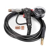
“>M16291-2 Lincoln Style Replacement Liner .023-.035 – Arc Weld by Masterweld is a replacement MIG gun liner for Lincoln-style MIG guns using small-diameter wire. Arc Weld Store lists this liner for Magnum 100L, Magnum PRO 100L, and Magnum PRO 175L guns, with Tweco cross-reference 35-40-15 and Lincoln cross-reference KP35-40-15.
This guide is built to reduce wrong-part orders by helping buyers verify gun series, wire size, liner cross-reference, torch parts, and related consumables before ordering.
Key Takeaways
Arc Weld Store lists this product as SKU M16291-2 – 1 EACH.
It is listed as a replacement .023-.035 liner for Lincoln-style MIG guns.
Arc Weld Store lists fitment for Magnum 100L, Magnum PRO 100L, and Magnum PRO 175L.
Arc Weld Store lists Tweco xref 35-40-15 and Lincoln xref KP35-40-15.
Lincoln’s KP35-40-15 reference is associated with .023-.035 in. cable liners for Magnum PRO 100L and 175L series guns.
Before ordering, verify your gun series, wire diameter, liner cross-reference, gun lead length, and whether your gun is an older Magnum 100L or a Magnum PRO 100L/175L style.
Product Overview
The M16291-2 is a small-wire replacement liner for Lincoln-style MIG guns. A liner is one of the most common causes of feeding problems when it is worn, kinked, contaminated, too tight for the wire, or mismatched to the wire diameter. Replacing the liner can help restore consistent wire feeding, reduce birdnesting, and reduce erratic starts when the rest of the MIG gun and drive system are in good condition.
Because MIG gun liners are fitment-sensitive parts, do not order by wire size alone. The correct liner depends on gun series, lead length, wire diameter, connector style, and cross-reference number. For this product, the key ordering identifiers are M16291-2, 35-40-15, and KP35-40-15.
Replacing a worn or contaminated liner in a compatible Lincoln-style MIG gun.
Feeding .023, .030, or .035 in. wire where the gun and liner fitment are verified.
Repairing wire feed issues on Magnum 100L, Magnum PRO 100L, or Magnum PRO 175L applications listed by Arc Weld Store.
Maintenance departments keeping common MIG gun wear parts on hand.
Shops cross-referencing Lincoln KP35-40-15 or Tweco 35-40-15 style liners.
Key Specs
Material/conduit type
M16291-2 Lincoln Style Replacement Liner .023-.035 – Arc Weld by Masterweld
Arc Weld Store SKU
M16291-2 – 1 EACH
Product type
MIG gun replacement liner
Wire size listed by Arc Weld Store
.023-.035 in.
Gun fitment listed by Arc Weld Store
Lincoln-style MIG guns: Magnum 100L, Magnum PRO 100L, Magnum PRO 175L
Tweco cross-reference listed by Arc Weld Store
35-40-15
Lincoln cross-reference listed by Arc Weld Store
KP35-40-15
Package quantity
1 each
Exact liner length for M16291-2
Unknown (Verify)
Material / conduit type
Unknown (Verify)
Compatible wire materials
Unknown (Verify)
Compatibility / Fitment Notes
Arc Weld Store lists this liner for Magnum 100L, Magnum PRO 100L, and Magnum PRO 175L Lincoln-style MIG guns. Weld Support Parts breakdown pages also list KP35-40-15 in Magnum 100L and Magnum PRO 100L liner sections, which supports using the gun parts breakdown to confirm the liner family before ordering.
Wire size: Match the liner to the wire being run. This product is listed for .023-.035 in. wire.
Gun series: Confirm whether your gun is Magnum 100L, Magnum PRO 100L, Magnum PRO 175L, or another Lincoln-style gun.
Cross-reference: Verify M16291-2 against Tweco 35-40-15 or Lincoln KP35-40-15 before ordering.
Lead length: Confirm the liner can be trimmed or matched correctly to the gun lead length. Exact M16291-2 liner length: Unknown (Verify).
Consumables: Contact tips, nozzles, and diffusers may differ between Magnum 100L and Magnum PRO 100L gun families. Do not assume parts interchange across all 100L-style guns.
Aluminum wire: This liner is not verified as a Teflon or aluminum-specific liner. Aluminum compatibility: Unknown (Verify).
Before You Order
Confirm the part number needed: M16291-2.
Confirm your current liner cross-reference: KP35-40-15 or 35-40-15.
Confirm your MIG gun series: Magnum 100L, Magnum PRO 100L, Magnum PRO 175L, or other.
Confirm your wire diameter: .023, .030, or .035 in.
Confirm your wire type: solid steel, stainless, flux-cored, aluminum, or other. Compatibility: Unknown (Verify).
Confirm the gun lead length and whether the liner must be trimmed during installation.
Inspect the contact tip, diffuser, nozzle, drive rolls, and inlet guide for wear before blaming the liner alone.
Confirm the drive roll groove matches the wire size and wire type.
Confirm the spool brake is not too tight and the wire is not rusty, dirty, kinked, or oversized.
Use the MIG gun parts breakdown to verify the correct liner family before ordering replacement parts.
Accessories / Compatible Products
These related Arc Weld Store products are technically relevant to the same Lincoln-style MIG gun repair workflow, but compatibility must be verified by exact gun model and application before ordering.
“>Lincoln Electric KP2744-035T Tapered .035 Contact Tips, 10 pack — relevant when using .035 wire on compatible Magnum PRO gun setups. Compatibility: Unknown (Verify).
Weld Support Parts Breakdown Reference
For parts-diagram confirmation, review the Lincoln Magnum 100L MIG gun parts breakdown. The breakdown lists the Magnum 100L K530-6 gun and includes KP35-40-15 in the liner section. Weld Support Parts also lists a Magnum PRO 100L breakdown with KP35-40-15 in the liner section. Use these pages for technical support and parts identification only; use Arc Weld Store for the product order link.
Common Applications
Repairing poor wire feed on compatible Lincoln-style MIG guns.
Replacing a liner after rusted or dirty wire has contaminated the conduit.
Changing back to small wire after a gun has been set up with a larger liner.
Preventing downtime on shop MIG guns used for light fabrication and repair.
Supporting .023-.035 in. MIG wire applications where gun and liner fitment are verified.
Shipping / Returns Notes
Arc Weld Store lists this item as typically shipping within 1–2 business days, shipping from Corydon, Indiana, with free ground shipping to the lower 48 on qualifying orders. Returns are listed as accepted on unused items in original packaging. Arc Weld Store also advises contacting sales@arcweldinc.com with the part number, equipment model, and application before opening an incorrect item.
FAQ
What is M16291-2 used for?
M16291-2 is a replacement .023-.035 in. MIG gun liner for Lincoln-style MIG guns listed by Arc Weld Store, including Magnum 100L, Magnum PRO 100L, and Magnum PRO 175L.
What is the Lincoln cross-reference for M16291-2?
Arc Weld Store lists Lincoln xref KP35-40-15 for M16291-2.
What is the Tweco cross-reference for M16291-2?
Arc Weld Store lists Tweco xref 35-40-15 for M16291-2.
Will this liner fit a Magnum 100L gun?
Arc Weld Store lists Magnum 100L fitment. Confirm your exact gun model, lead length, and liner cross-reference before ordering.
Will this liner fit a Magnum PRO 100L or Magnum PRO 175L?
Arc Weld Store lists Magnum PRO 100L and Magnum PRO 175L fitment. Verify the gun model and the KP35-40-15 cross-reference before ordering.
Can I use this liner for aluminum wire?
Aluminum wire compatibility is Unknown (Verify). The product page does not identify this as a Teflon or aluminum-specific liner.
Should I replace the contact tip when replacing the liner?
Inspect the contact tip during liner replacement. A worn, oversized, clogged, or incorrect contact tip can cause feed issues even after a new liner is installed. Confirm tip series and wire size before ordering tips.
Safety Notes
Turn off and disconnect welding power before servicing the MIG gun.
Allow the gun, nozzle, diffuser, and contact tip to cool before handling.
Trim and deburr the liner carefully to avoid wire shaving and feeding problems.
Wear eye protection when cutting liner material or clearing wire from the gun.
Follow the welder manufacturer’s manual, MIG gun documentation, OSHA requirements, AWS safety guidance, ANSI Z49.1, and employer lockout/tagout procedures.
Sources Checked
Arc Weld Store product page for M16291-2 Lincoln Style Replacement Liner .023-.035 – Arc Weld by Masterweld.
Arc Weld Store related product pages for M16291-1, Lincoln Electric K4528-1 Magnum PRO 100L MIG Gun, Lincoln S19725 Trigger Switch, and Lincoln KP2744-035T contact tips.
Lincoln Electric KP35-40-15 cable liner manufacturer listing.
Weld Support Parts Lincoln Magnum 100L K530-6 breakdown.
Weld Support Parts Lincoln Magnum PRO 100L K3080-1 breakdown.
OSHA welding, cutting, and brazing safety references.
AWS welding safety resources and ANSI Z49.1 safety references.
End CTA: Ready to verify the cross-reference and order the liner?
“>Hypertherm Powermax45 SYNC Plasma Cutter for Metalworking, 20 Ft. Handheld Torch, 088560 is a 45 amp professional plasma cutting system built for metalworkers who need simplified setup, single-piece cartridge consumables, and reliable hand cutting performance. This guide is focused on ordering accuracy: power input, torch configuration, cut capacity, cartridge selection, air supply, and the fitment checks to complete before purchasing consumables or accessories.
Key Takeaways
Arc Weld Store lists this system as Hypertherm Powermax 45 SYNC Plasma Cutter for Metalworking, 20 Ft. Handheld Torch, SKU 088560.
Hypertherm identifies the Powermax45 SYNC as a system for cutting, gouging, and marking with SmartSYNC torch communication and single-piece cartridge consumables.
Part number 088560 is the CSA 200–240 V, 1-phase standard power supply configuration with a 75-degree hand torch and 20 ft torch lead.
Hypertherm lists recommended cut capacity at 5/8 in. at 20 ipm, severance capacity at 1-1/8 in. at 5 ipm, and pierce capacity at 1/2 in.
The system uses clean, dry, oil-free air or nitrogen for cutting and gouging. Air quality should be verified before use to protect cut quality and cartridge life.
Cartridge selection matters. Do not order cartridges by appearance alone; verify amperage, process, torch type, and material thickness.
Product Overview
The Hypertherm Powermax45 SYNC 088560 is a portable plasma cutting system for fabrication, repair, maintenance, education, HVAC/mechanical work, agricultural repair, and metal shop use. Arc Weld Store lists this configuration with a 20 ft handheld torch and identifies it as a professional plasma cutter for metalworking applications.
The main advantage of the SYNC platform is simplified consumable management. Instead of stacking separate plasma consumables, Hypertherm’s SmartSYNC platform uses a single-piece cartridge system. Hypertherm also identifies RFID-enabled SmartSYNC torches and cartridges that automatically set amperage and operating mode when correctly paired with the system. That reduces setup mistakes, but it does not remove the need to verify the correct cartridge for the cut type, amperage, torch, and material thickness.
Fabrication shops cutting mild steel, stainless steel, and aluminum within verified capacity limits.
Maintenance teams that need a portable plasma cutter for repair and plant work.
HVAC and mechanical contractors cutting sheet, plate, brackets, and field-fit parts.
Farm, equipment, and trailer repair where portability and clean cuts reduce grinding time.
Training programs that want simplified cartridge selection and reduced consumable stack errors.
Metalworkers who want hand cutting first and may later compare compatible mechanized configurations.
Key Specs
Product
Hypertherm Powermax45 SYNC Plasma Cutter for Metalworking, 20 Ft. Handheld Torch
Arc Weld Store SKU
088560
Brand
Hypertherm
Configuration
CSA 200–240 V standard power supply with 75-degree hand torch and 20 ft torch lead
Processes
Plasma cutting, gouging, and marking when set up with the correct torch/cartridge configuration
Input voltage
200–240 V, 1-phase, 50/60 Hz
Input current at 6.9 kW
39/32 A at 200–240 V, 1-phase
Output current
9–45 A
Rated output voltage
155 VDC
Duty cycle at 104°F / 40°C
50% at 45 A; 60% at 41 A; 100% at 32 A
Recommended cut capacity
5/8 in. at 20 ipm
Severance capacity
1-1/8 in. at 5 ipm
Pierce capacity
1/2 in. for handheld use or with automatic torch height control
Typical gouge capacity
7.5 lb per hour metal removal; 0.12 in. deep x 0.26 in. wide groove profile
Gas supply
Clean, dry, oil-free air or nitrogen for cutting and gouging; marking gas support depends on setup and cartridge
Recommended gas inlet flow rate / pressure
188 l/min at 5.9 bar; 400 scfh / 6.7 scfm at 90 psi
Input power cable length
10 ft
Power supply type
Inverter – IGBT
Engine drive requirement
12.5 kVA / 10 kW for full 45 A output
Dimensions with handles
17.4 in. D x 6.8 in. W x 14.1 in. H
Weight with 20 ft torch
31 lb
Warranty listed by Hypertherm literature
Power supply: 6-year; Torch: 1-year
CPC / voltage divider / serial port
Not listed for 088560 standard configuration; verify before ordering for CNC or mechanized integration
Compatibility / Fitment Notes
This product is a complete plasma cutting system configuration, but consumables and accessories still require fitment verification. The most important checks are system part number, torch style, input power, cartridge amperage, gas supply, material thickness, and intended cutting process.
System configuration: 088560 is the standard CSA 200–240 V, 1-phase configuration with a 75-degree hand torch and 20 ft lead.
Hand cutting: The 75-degree hand torch configuration is appropriate for manual cutting applications when paired with the correct cartridge.
Mechanized cutting: Do not assume this 088560 package has CPC, voltage divider, serial communication, machine torch, or remote pendant features. Verify before purchasing for CNC table use.
Cartridge fitment: Hypertherm lists Powermax cartridge options for drag cutting, mechanized/standoff cutting, max removal gouging, max control gouging, and FineCut applications. Match the cartridge to the process and amperage.
Gas quality: Poor air quality can shorten consumable life and degrade cut quality. Confirm clean, dry, oil-free air before cutting.
Power supply: Confirm 200–240 V single-phase power and circuit requirements before ordering. This is not a 120 V plasma cutter.
Before You Order
Confirm the exact Arc Weld Store product SKU: 088560.
Confirm your available input power is 200–240 V, 1-phase, 50/60 Hz.
Confirm breaker, wiring, plug, receptacle, and extension cord requirements against Hypertherm documentation and local electrical code.
Confirm whether you need handheld cutting only or CNC/mechanized capability.
Confirm the torch style: this configuration is listed with a 75-degree hand torch and 20 ft torch lead.
Confirm the cut thickness range: recommended 5/8 in., severance 1-1/8 in., and pierce 1/2 in.
Confirm air compressor capacity, dryness, oil separation, and regulator/filter setup.
Confirm cartridge family and amperage before ordering consumables.
Confirm whether you need drag cutting, FineCut, gouging, marking, or mechanized/standoff cartridges.
Confirm PPE requirements for plasma arc radiation, sparks, fumes, noise, and hot slag.
Accessories / Compatible Products
Consumables and accessories should be selected by system part number, torch type, process, and material thickness. Do not assume every SmartSYNC cartridge is correct for this 45 amp hand system. Compatibility must be verified against the Powermax45 SYNC documentation before ordering.
“>Hypertherm SmartSYNC Cartridge or Adapter 45 A Drag Cutting 428927 — relevant for 45 A drag cutting where the cartridge and torch/system fitment are confirmed.
“>Hypertherm SmartSYNC Cartridge or Adapter 30–45 A Hand FineCut 428928 — relevant for fine feature hand cutting on thin mild steel and stainless steel where fitment is confirmed.
“>Hypertherm Powermax 30 AIR Portable Plasma Cutter with 15 ft Lead and Internal Compressor — compare if portability and built-in air supply are more important than 45 amp output.
“>Hypertherm 428162 Duramax Hyamp Hand Torch Trigger Start Switch Replacement — replacement torch part category example; compatibility with Powermax45 SYNC SmartSYNC torch is Unknown (Verify).
Weld Support Parts Breakdown Reference
For torch and consumable identification support, review the Hypertherm plasma torch parts breakdown. The page includes Powermax 45 Sync Smart Sync torch listings, including 75-degree hand torch and other torch styles. Use this only as a technical breakdown reference; order from Arc Weld Store after confirming the exact torch, cartridge, and system configuration.
Common Applications
Hand plasma cutting of plate, sheet, brackets, tabs, and repair parts.
Drag cutting where the correct drag cartridge is installed.
Fine feature cutting when a verified FineCut cartridge is selected.
Light gouging and metal removal using the correct gouging cartridge.
Shop repair, trailer repair, equipment maintenance, and field fabrication.
Educational and training environments where simplified consumable setup reduces errors.
Metalworking jobs where cartridge tracking and end-of-life consumable detection help reduce downtime.
Shipping / Returns Notes
Arc Weld Store lists this product as typically shipping within 1–2 business days, shipping from Corydon, Indiana, with free ground shipping to the lower 48 on qualifying orders. Returns are listed as accepted on unused items in original packaging. For fitment help, Arc Weld Store advises emailing sales@arcweldinc.com with the part number, equipment model, and application before opening an incorrect item.
FAQ
What is the Arc Weld Store SKU for this Hypertherm Powermax45 SYNC?
Arc Weld Store lists the SKU as 088560.
What torch comes with Hypertherm 088560?
Hypertherm ordering information identifies 088560 as the CSA 200–240 V standard power supply configuration with a 75-degree hand torch and 20 ft torch lead.
What input power does the Powermax45 SYNC 088560 require?
The verified CSA specification is 200–240 V, 1-phase, 50/60 Hz. Confirm your electrical service, plug, receptacle, circuit protection, and local code requirements before ordering.
How thick can the Powermax45 SYNC cut?
Hypertherm lists recommended cut capacity at 5/8 in. at 20 ipm, severance capacity at 1-1/8 in. at 5 ipm, and pierce capacity at 1/2 in. for handheld use or with automatic torch height control.
Does the 088560 package include CNC ports?
Not confirmed for this standard 088560 configuration. Hypertherm lists separate configurations with CPC port, voltage divider, and serial port options. Verify before buying for mechanized or CNC use.
Which SmartSYNC cartridge should I buy?
Choose by process, amperage, torch type, and material thickness. For example, Hypertherm lists cartridge options for 45 A drag cutting, FineCut hand cutting, mechanized/standoff cutting, and gouging. Compatibility: Unknown (Verify) until the exact torch, system, and application are confirmed.
Can I use shop air with this plasma cutter?
Yes, when the air supply meets Hypertherm requirements. The system requires clean, dry, oil-free air or nitrogen. Verify compressor capacity, moisture control, filtration, and regulator setup before use.
Safety Notes
Read the Hypertherm operator manual and safety documentation before installing, operating, or servicing the system.
Plasma cutting produces intense arc radiation, sparks, hot slag, fumes, and noise. Use appropriate PPE and protect bystanders.
Wear ANSI Z87.1-compliant eye and face protection suitable for plasma cutting.
Use welding/cutting gloves, flame-resistant clothing, hearing protection, and respiratory protection where required.
Keep flammable materials away from the cutting area and inspect for fire risk before and after cutting.
Disconnect power and allow the torch and cartridge to cool before servicing.
Use ventilation or local exhaust appropriate for the metal, coating, and work area.
Follow OSHA requirements, AWS safety guidance, ANSI Z49.1, the Hypertherm manual, local code, and employer safety procedures.
Sources Checked
Arc Weld Store product page for Hypertherm Powermax 45 SYNC Plasma Cutter for Metalworking, 20 Ft. Handheld Torch, SKU 088560.
%C2%AE-rogue-es-151ip-pro-stick-welder?utm_source=blog&utm_medium=internal&utm_campaign=esab-rogue-es-151ip-pro-stick-welder-guide”>ESAB Rogue ES 151iP PRO Stick Welder is a portable inverter-based welding power source built for Stick/SMAW, MMA pulse, and Live TIG/GTAW use. This guide focuses on ordering accuracy: input power, output range, electrode size limits, included items, TIG limitations, and the checks to make before you add it to a shop, field service truck, maintenance department, or training lab.
Key Takeaways
Arc Weld Store lists this model as ESAB Rogue ES 151IP PRO Stick Welder, SKU 0705002021.
The ESAB manual identifies the Rogue ES 151iP PRO as intended for MMA/SMAW/Stick, MMA pulse, and TIG/GTAW welding.
The 151iP PRO supports 120 V or 230 V single-phase input and automatically adjusts to the supplied input voltage when correctly protected.
For Stick welding, the ESAB manual lists a setting range of 20–150 A on 230 V and 20–110 A on 120 V.
Arc Weld Store notes that the Rogue ES 151iP PRO welds electrodes up to 3.2 mm, or 1/8 in.
Live TIG capability is available, but the TIG torch is sold separately; TIG torch model and consumable compatibility must be verified before ordering TIG accessories.
Product Overview
The ESAB Rogue ES 151iP PRO is a compact DC Stick/TIG power source for users who need a portable welder with controlled arc characteristics, dual-voltage flexibility, and pulse Stick capability. Arc Weld Store describes the machine as using high-performance power electronics and digital control to provide a precise, consistent arc. It is intended for professional users welding alloyed steel, non-alloyed steel, stainless steel, and cast iron.
For buyers comparing this machine to a higher-output Stick welder, the main ordering question is electrode size and available input power. The 151iP PRO is the smaller Rogue PRO option in this comparison, with Arc Weld Store noting electrode capacity up to 1/8 in. If your work regularly requires 5/32 in. electrodes, compare the
Maintenance crews needing a portable DC Stick welder for repair work.
Fabrication shops that want a compact SMAW power source for common electrodes up to 1/8 in.
Field service users who have access to suitable 120 V or 230 V single-phase power.
Training programs that need Stick and Live TIG capability in a small inverter package.
Users who want Pulse SMAW functionality to help manage heat input on thinner work or out-of-position welds.
Key Specs
Product
ESAB Rogue ES 151iP PRO Stick Welder
Arc Weld Store SKU
0705002021
Processes listed by ESAB manual
MMA / SMAW / Stick, MMA pulse, TIG / GTAW
Input voltage
230 V ±15%, 1-phase, 50/60 Hz; 120 V ±15%, 1-phase, 50/60 Hz
Stick setting range
20–150 A at 230 V; 20–110 A at 120 V
Live TIG setting range
10–150 A at 230 V; 10–140 A at 120 V
Stick duty cycle at 230 V
150 A / 26 V at 25%; 97 A / 23.9 V at 60%; 75 A / 23 V at 100%
Stick duty cycle at 120 V
110 A / 24.4 V at 25%; 70 A / 22.8 V at 60%; 55 A / 22.2 V at 100%
Maximum electrode size stated by Arc Weld Store
3.2 mm / 1/8 in.
Dimensions
15.8 x 6 x 10.4 in.
Weight
20.28 lb
Enclosure class
IP23S
Generator note
ESAB manual recommends generators with AVR or equivalent/better regulation and 7 kW rated power
Included equipment per ESAB manual
Power source, work clamp leadset, electrode holder leadset, power adapter, shoulder strap, instruction manual, quick start guide
TIG torch
Sold separately per Arc Weld Store product description
Compatibility / Fitment Notes
This is a welding power source, so the most important fitment checks are electrical supply, electrode size, process setup, cable connections, duty cycle, and accessory selection.
Input power: Confirm whether the jobsite or shop power is 120 V or 230 V single-phase and verify the rating plate before use.
Stick polarity: The ESAB manual states that Stick welding cable polarity depends on the electrode used; check the electrode packaging before connecting the electrode holder and work clamp.
Electrode capacity: Arc Weld Store states that the 151iP PRO welds electrodes up to 3.2 mm / 1/8 in.
Live TIG: The unit can TIG weld mild steel or stainless steel through Live TIG functionality, but TIG torch selection, torch connector, gas setup, tungsten size, cup size, and consumable family are not confirmed from the Arc Weld product page. Compatibility: Unknown (Verify).
Outdoor use: ESAB identifies IP23S enclosure class and states equipment marked IP23S is intended for indoor and outdoor use, but should not be operated in precipitation.
Before You Order
Confirm the exact product SKU needed: 0705002021.
Confirm available input voltage: 120 V or 230 V single-phase.
Confirm the circuit protection and wiring requirements against the ESAB manual and local electrical requirements.
Confirm your expected electrode diameter; this model is listed for electrodes up to 1/8 in.
Confirm the electrode type and required polarity from the electrode packaging.
Confirm whether your work requires more output than the 151iP PRO provides, especially if you routinely use 5/32 in. electrodes.
Confirm duty cycle requirements at the amperage you expect to run.
For Live TIG use, confirm torch model, connector style, shielding gas setup, regulator/flowmeter, tungsten size, cup size, collet size, and consumable family before ordering accessories.
Confirm whether the included work clamp leadset and electrode holder leadset lengths meet your setup needs.
For generator use, confirm the generator has AVR or equivalent/better regulation and adequate rated power.
Accessories / Compatible Products
Only order accessories after confirming process, electrode size, PPE needs, and TIG setup details. Do not assume TIG torch consumables fit this machine unless the torch model and consumable family are verified.
“>Black Stallion 25GL Goatskin TIG Welding Gloves — TIG glove option where dexterity is needed; verify size and application.
Weld Support Parts Breakdown Reference
No confirmed Weld Support Parts breakdown page was found for the ESAB Rogue ES 151iP PRO power source during source checking. Because the Arc Weld product page states that the TIG torch is sold separately and does not identify a torch model, TIG torch parts and consumables should be verified by torch model before ordering.
Common Applications
General steel maintenance welding.
Portable Stick welding on repair jobs where 120 V or 230 V single-phase power is available.
Stainless steel repair using suitable electrodes or verified Live TIG setup.
Cast iron repair where the correct electrode and procedure are selected.
Training environments where students need Stick setup, polarity checks, and arc control practice.
Thin-gauge or out-of-position Stick work where Pulse SMAW may help manage heat input and spatter.
Shipping / Returns Notes
Arc Weld Store lists this product as typically shipping within 1–2 business days, shipping from Corydon, Indiana, with free ground shipping to the lower 48 on qualifying orders. Returns are listed as accepted on unused items in original packaging. For ordering support, Arc Weld Store advises contacting sales@arcweldinc.com with the part number, equipment model, and application before opening an incorrect item.
FAQ
What is the Arc Weld Store SKU for the ESAB Rogue ES 151iP PRO?
Arc Weld Store lists the SKU as 0705002021.
Can the Rogue ES 151iP PRO run on 120 V and 230 V?
Yes. The ESAB manual lists the Rogue ES 151iP PRO for 120 V ±15% and 230 V ±15%, single-phase, 50/60 Hz input. Always verify the rating plate and electrical setup before use.
What size Stick electrodes can this welder run?
Arc Weld Store states that the Rogue ES 151iP PRO welds electrodes up to 3.2 mm / 1/8 in.
Does the ESAB Rogue ES 151iP PRO include a TIG torch?
No. Arc Weld Store states that the machine can TIG weld mild steel or stainless steel through Live TIG functionality, but the TIG torch is sold separately.
What comes with the Rogue ES 151iP PRO?
The ESAB manual lists the included equipment as the power source, work clamp leadset, electrode holder leadset, power adapter, shoulder strap, instruction manual, and quick start guide.
Should I buy the Rogue ES 151iP PRO or the Rogue ES 201iP PRO?
Choose based on verified output needs, electrode diameter, input power, and duty cycle. Arc Weld Store states that the 151iP PRO welds up to 1/8 in. electrodes, while the 201iP PRO is listed for electrodes up to 5/32 in.
Safety Notes
Read the ESAB instruction manual before installation, operation, maintenance, or troubleshooting.
Use appropriate welding PPE, including helmet, eye protection, gloves, protective clothing, and respiratory controls where required.
Keep your head out of welding fumes and use ventilation or local exhaust appropriate for the material, electrode, coating, and work area.
Do not operate equipment marked IP23S in precipitation.
Confirm grounding, circuit protection, polarity, and cable condition before welding.
Follow OSHA requirements, AWS safety guidance, ANSI Z49.1, local codes, employer safety procedures, and the electrode manufacturer’s SDS.
Sources Checked
Arc Weld Store product page for ESAB Rogue ES 151IP PRO Stick Welder, SKU 0705002021.
ESAB Rogue ES 151iP PRO / ES 201iP PRO instruction manual, document 0448 684 001 US.
ESAB Rogue ES 151iP manufacturer product page.
Arc Weld Store related product pages for ESAB Rogue ES 201iP PRO, Weldcote Klearview welding helmet, Revco GM1611 gloves, and Black Stallion 25GL gloves.
Weld Support Parts site search for relevant ESAB Rogue ES 151iP PRO breakdown support.
OSHA welding, cutting, and brazing safety references.
AWS welding safety resources and ANSI Z49.1 safety references.