Tag: welding consumables

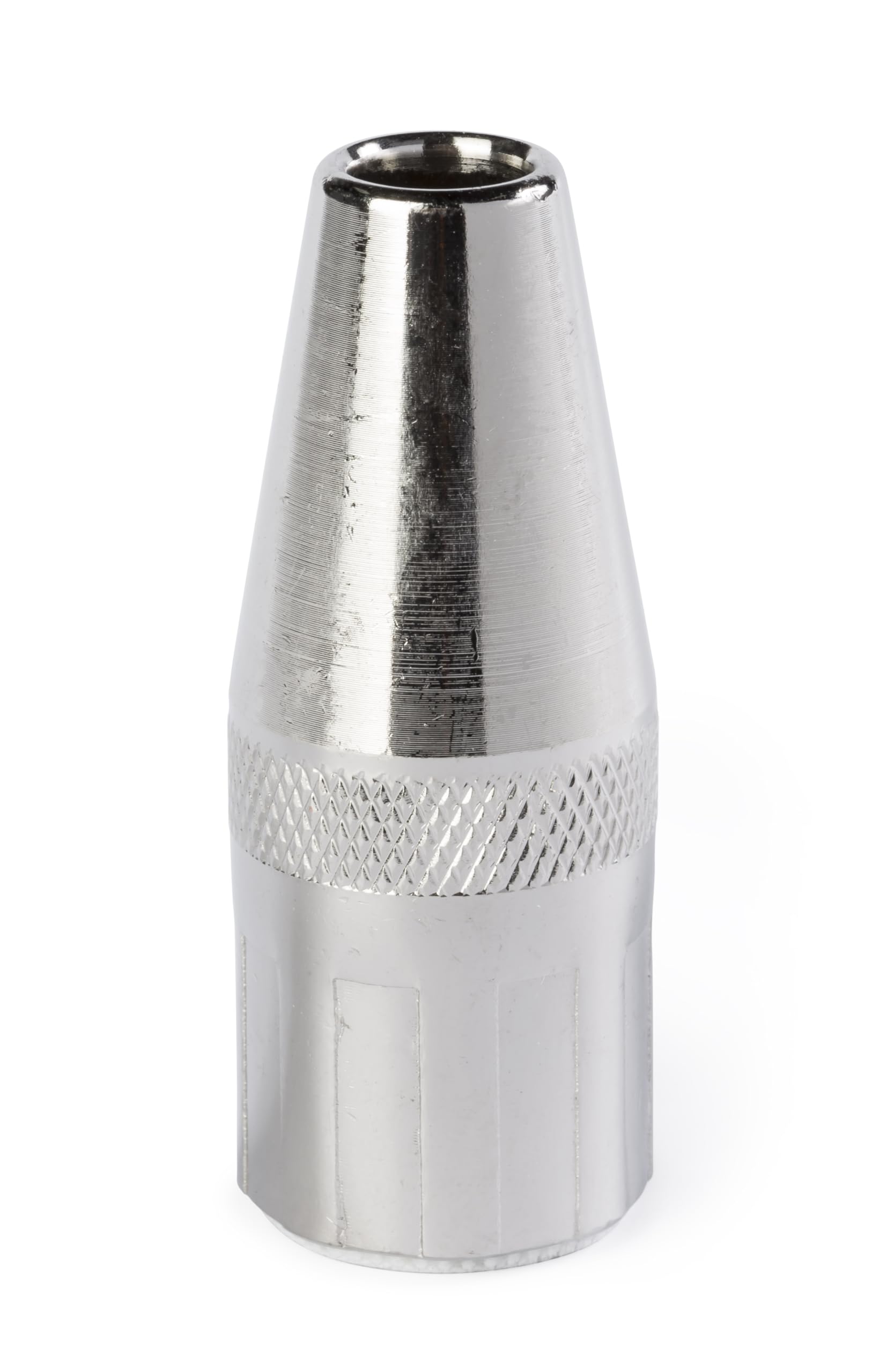
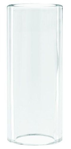
  • Bernard NS-1218C Centerfire Nozzle, 1/8″ Recess, 1/2″, for G-Gun, Pack of (1): Replacement Part Breakdown

    The Bernard NS-1218C Centerfire Nozzle is a replacement part listing for a MIG gun nozzle used on a G-Gun setup. For buyers, maintenance teams, and welding support staff, the practical question is not just what the part is called, but whether the nozzle geometry, recess, and contact-point fit match the gun body, diffuser, and production process requirements. This article breaks down the part listing in a way that supports inspection, replacement planning, and troubleshooting.

    Product reference: Bernard NS-1218C Centerfire Nozzle, 1/8″ Recess, 1/2″, for G-Gun, Pack of (1) B004HFBLMA. The Amazon product reference is included for identification only.

    Key Takeaways

    • Use the nozzle as a wear part, not a permanent component.
    • Confirm the gun family, front-end stack, and recess requirement before ordering a replacement.
    • Check for spatter buildup, heat damage, distortion, and thread or fit issues during scheduled maintenance.
    • If fit or compatibility is not confirmed by your internal documentation, mark it as Unknown (Verify).

    What this part is used for

    A MIG nozzle directs shielding gas and helps shield the arc zone from contamination. On a production line, nozzle condition affects gas coverage, access to the joint, and how often operators need to stop for cleaning. The listing name indicates a 1/8″ recess and 1/2″ size, but exact dimensional interpretation, thread style, and compatibility with a specific G-Gun assembly should be verified against the gun manual or existing part number cross-reference. Unknown (Verify) if your shop does not have that documentation.

    For support teams, the practical job is to confirm three things:

    • the nozzle matches the gun front end;
    • the recess matches the welding position and access requirements;
    • the replacement does not alter arc access, visibility, or gas coverage in a way that affects production.

    Inspection and replacement checks

    Before installing a replacement nozzle, inspect the current setup and compare it to the spare. Use these checks:

    Check: look for spatter buildup inside the nozzle and at the outlet edge. Heavy buildup can restrict gas flow and make cleaning ineffective.

    Inspect: inspect the nozzle shape for oval wear, heat discoloration, cracks, or impact damage. Deformed nozzles can create inconsistent gas coverage or poor access to the joint.

    Verify: verify that the recess depth and front-end reach match the production application. If the exact recess requirement is not documented, mark it Unknown (Verify) before release to production.

    Check: confirm the nozzle seats correctly on the diffuser or adapter. Cross-threading, galling, or loose fit can cause intermittent performance issues.

    Inspect: confirm the wire stickout, contact tip position, and nozzle alignment are consistent with your normal setup. If a replacement shifts the front end, the machine may still run, but the weld results may change.

    Troubleshooting support notes

    If operators report erratic shielding, excess spatter, or difficulty maintaining a stable weld, the nozzle should be part of the first inspection pass. The nozzle is not always the root cause, but it is a common wear item that can contribute to front-end problems.

    Check: gas flow at the gun. Low flow may come from a blockage, a leak, or a supply issue elsewhere in the system.

    Inspect: the nozzle for internal obstructions or spatter bridges that could deflect gas away from the arc.

    Verify: that the front-end parts are installed in the correct order for your G-Gun configuration. If your parts list is incomplete, do not assume the stack-up is correct.

    Check: the wear state of the contact tip and diffuser. A nozzle replacement alone will not correct problems caused by worn or misaligned front-end parts.

    Parts and procurement notes

    The Amazon reference for this item is available through the product card below. Use it as an identification aid when matching a shop part number to an order request. Do not assume that the listing alone proves compatibility with every Bernard or G-Gun variant.

    No products found.

    When the internal maintenance record is incomplete, compare the removed nozzle to the spare and document the part number, front-end style, and recess setup before issue. For buyer guides and support teams, that step reduces avoidable returns and wrong-part installs.

    When to replace rather than clean

    Cleaning is reasonable when spatter is light and the nozzle retains its original shape. Replacement is the better option when the nozzle is heat damaged, bent, cracked, or repeatedly plugs with buildup. In general, a nozzle that no longer holds a consistent bore or outlet shape should be treated as end of life for shop use.

    If your process is sensitive to access or visibility, a worn nozzle can change the feel of the torch at the workpiece. That does not mean the part is always defective; it means the worn front end is no longer controlled enough for repeatable production use.

    Safety notes

    • Allow the gun and front-end parts to cool before handling.
    • Use appropriate gloves when removing spatter or hot consumables.
    • Do not force parts that do not seat correctly.
    • Verify gas and power isolation before maintenance work.
    • Use shop procedures for inspection and lockout where applicable.

    FAQ

    Is this nozzle guaranteed to fit every G-Gun?
    No. The listing says it is for G-Gun, but exact compatibility with your specific gun variant should be verified against your parts documentation. Unknown (Verify) if the match is not documented.

    Does the 1/8″ recess affect welding performance?
    It can affect access, arc shielding, and visibility at the joint. The right recess depends on the application, but the exact effect on your process should be verified in your shop setup.

    Should a worn nozzle be cleaned or replaced?
    Light spatter can often be cleaned. Replace the nozzle if it is cracked, badly distorted, heavily heat damaged, or repeatedly contaminated after cleaning.

    Can I order this part based only on the title?
    Use the title as a starting point, not the final approval. Match the part number, gun front end, and internal maintenance record before release.

    Sources Checked

    Note: No WSP lookup page or filler metal finder page was provided for this task. No compatibility, certification, price, or availability claims were added.

    Disclosure: As an Amazon Associate, Weld Support Parts may earn from qualifying purchases.

    Related Weld Support Guides

  • How to Choose TIG Tungsten for Mild Steel and Stainless

    How to Choose TIG Tungsten for Mild Steel and Stainless

    Stainless Steel GTAW (Tig Welding)

    Choosing the right tungsten for TIG welding is mostly about matching the electrode to the job, the machine, and the material condition. For mild steel and stainless steel, the goal is stable arc starts, controlled heat input, and a clean puddle without unnecessary contamination. The wrong tungsten can still make a weld, but it usually makes setup harder and increases rework.

    This guide focuses on tig tungsten selection for mild steel and stainless steel. It covers tungsten type, diameter, and basic inspection steps. Where exact compatibility depends on your power source or process setup, treat it as Unknown (Verify) and confirm in the machine manual, electrode packaging, or your welding procedure.

    Key Takeaways

    • Use tungsten type based on current mode, arc stability needs, and machine recommendations.
    • Diameter should match amperage demand and electrode extension, not guesswork.
    • Mild steel and stainless steel usually use similar TIG setup principles, but joint condition and heat control matter more on stainless.
    • Check tip condition before every job. A contaminated or overheated tungsten causes poor starts and arc wander.
    • Verify the exact tungsten classification and diameter against your equipment and procedure before production welding.

    Start With the Base Metal and Power Source

    For mild steel and stainless steel, TIG tungsten selection usually begins with the welding current type and the electrode behavior you want. The work material matters, but the machine and polarity matter more. If your setup is AC, DCEN, pulsed TIG, or inverter-based, the ideal tungsten can change. Exact machine compatibility is Unknown (Verify) unless your equipment manual says otherwise.

    For steel and stainless, most buyers are looking for a tungsten that starts clean, holds a point well, and resists excessive balling or tip breakdown under the expected amperage. If the joint is thin and the operator needs precise control, a smaller diameter and a properly prepared tip are often easier to manage. If the amperage is higher, choose a larger diameter that can carry the load without overheating.

    How to Choose Tungsten Type

    Do not choose by color alone. Color codes and alloy content vary by supplier, and relying on color without checking the label is a common error. Verify the actual electrode type printed on the package.

    • Pure tungsten: May be used in some AC applications. For mild steel and stainless on DC, this is usually not the first choice. Verify against your procedure.
    • Thoriated tungsten: Traditionally used for DC TIG because it can provide strong arc starts and tip retention. However, handling and grinding dust safety concerns apply. Follow site safety rules and verify whether it is permitted in your shop.
    • Ceriated tungsten: Commonly used for lower-amp starting and general-purpose TIG work. Exact performance depends on the power source. Verify with your procedure.
    • Lanthanated tungsten: Often selected for stable starts and broad usability. Specific grades and current ranges are Unknown (Verify) unless identified by the supplier and machine manual.

    For mild steel and stainless, many shops prefer a general-purpose DC tungsten that starts clean and stays stable under normal amperage. If you are unsure which tungsten family your procedure requires, verify the WPS, the machine manual, and the filler/consumable guide before welding.

    Choose Diameter by Amperage and Control

    Diameter selection is practical, not theoretical. A tungsten that is too small overheats, degrades the tip, and contaminates the weld. A tungsten that is too large can be harder to start and less responsive at low amperage.

    Use these checks:

    • Check the target amperage range. If the job calls for low current and fine control, start with a smaller diameter. If the current is moderate to high, step up the diameter.
    • Inspect the joint thickness. Thin material usually needs tighter heat control. Thicker material may justify a larger electrode.
    • Verify stickout and gas coverage. Excessive stickout increases contamination risk and may require better shielding or a different setup.
    • Check the cup size and torch body. Torch limitations can make a large tungsten impractical in tight areas.

    Exact diameter-to-amperage charts vary by manufacturer and process. If you do not have a current chart from the tungsten supplier or your procedure, use Unknown (Verify) and confirm before production use.

    Troubleshooting: When the Tungsten Is Not Working

    If the arc is unstable, do not assume the tungsten is the only problem. Work through the setup methodically.

    Check

    • Check whether the tungsten tip matches the current type and joint requirement.
    • Check for contamination from touching the puddle, filler rod, or filler dust.
    • Check shielding gas flow, cup condition, and gas lens condition if used.
    • Check whether the grind marks run lengthwise, not around the electrode.

    Inspect

    • Inspect the tip for balling, flat spots, or a dull overheated end.
    • Inspect the collet and back cap for poor clamping or overheating.
    • Inspect the arc start quality. Hard starts can indicate tip prep or machine issue.
    • Inspect the weld surface for discoloration that suggests shielding gas problems.

    Verify

    WSP Lookup Reference

    For stainless TIG wire selection context and related GTAW support content, review the WSP lookup page: Stainless Steel GTAW (Tig Welding). This page is useful as a supporting reference for stainless process planning, but it does not replace your WPS or machine documentation.

    Safety Notes

    • Do not grind or handle tungsten dust without shop-approved dust control and PPE.
    • Follow site rules for thoriated tungsten, if used. Dust inhalation risk and disposal requirements may apply.
    • Keep the torch de-energized when changing tungsten.
    • Use proper eye protection during grinding and arc starting.
    • Verify ventilation, shielding gas supply, and fire controls before welding stainless or mild steel.

    FAQ

    What tungsten type is best for mild steel and stainless?

    There is no single best answer without the procedure. Many shops use a general-purpose DC tungsten with good arc-start behavior. Exact preference is Unknown (Verify) until you confirm the machine, polarity, and WPS.

    Should I use the same tungsten for mild steel and stainless?

    Often, yes, if the amperage range and machine setup are similar. But do not assume. Verify your procedure, especially if the work includes thin stainless, pulsed TIG, or tight cosmetic requirements.

    How do I know if my tungsten diameter is too small?

    Signs include overheating, rapid tip erosion, arc instability, and frequent contamination. Check the amperage demand first, then verify whether the diameter is undersized for the job.

    Can I use a blunt tip instead of a sharp point?

    Tip geometry depends on current type and machine setup. For many DC TIG jobs, a controlled point is preferred. Exact geometry is Unknown (Verify) unless your procedure specifies it.

    Sources Checked

    Before buying or loading tungsten, confirm the electrode type, diameter, and current setup against the machine manual and welding procedure. That is the fastest way to avoid contamination, unstable starts, and unnecessary grind time.

    Related Weld Support Guides

  • Contact Tip Compatibility Guide

    Tweco VTS30 Velocity Light Duty MIG Welding Contact Tip, 0.030" Wire Size, Standard (Pack of 10)
    “>Tweco VTS30 Velocity Light Duty MIG Welding Contact Tip, 0.030" Wire Size, Standard (Pack of 10)

    Contact tip compatibility depends on three basic checks: thread style, wire diameter, and the gun/nozzle system the tip is designed to fit. If any one of those is wrong, the tip may not seat correctly, wear early, or feed poorly.

    Key Takeaways

    • Match the contact tip to the wire diameter first.
    • Confirm the thread style and overall tip format used by the gun.
    • OEM and aftermarket tips may be interchangeable only when the physical fit is the same.
    • Do not assume all tips for the same brand are compatible across all guns.
    • If fit is unclear, use the gun model, nozzle type, and parts diagram to verify.

    How Contact Tip Compatibility Works

    A contact tip is not just a small copper wear part. It is part of the electrical and wire-feeding path. For proper operation, the wire must pass through the tip with the correct clearance, and the tip must mount correctly in the nozzle or diffuser system.

    Compatibility usually comes down to:

    • Wire diameter: Example sizes include 0.030, 0.035, 0.045, and others. Use the tip size that matches the wire size being run.
    • Thread style or mounting style: Some tips thread into the diffuser. Others are retained by a specific nozzle or velocity-style system. Exact thread dimensions vary by gun system and are Unknown (Verify) unless confirmed by the parts breakdown.
    • Gun family / consumable system: The same wire size can use different tips depending on whether the gun is Tweco-style, Bernard-style, Lincoln-style, or another system. Verify by gun model.

    Wire Diameter vs. Tip Size

    The most common error is selecting a tip that does not match the wire. A 0.030 tip should generally be used with 0.030 wire. If the fit is too tight, feeding can become erratic. If the fit is too loose, arc stability and current transfer can suffer.

    Wire Diameter Typical Tip Size Notes
    0.030 in. 0.030 in. Matches the wire size used in the provided ArcWeld product.
    0.035 in. 0.035 in. Common shop size; verify gun and drive roll setup.
    0.045 in. 0.045 in. Used for higher deposition applications; verify consumable system.

    If the wire is oversized for the tip, feeding problems are common. If the wire is undersized for the tip, the arc may become less consistent. For exact tolerances, use the gun manufacturer’s parts chart. Unknown (Verify).

    Thread Styles and Tip Mounting

    Some contact tips thread directly into the diffuser. Others are part of a nozzle system or use a specific retained-style consumable. The thread style matters because a tip can look similar and still not fit.

    Common fit questions to verify:

    • Does the tip thread into the diffuser, or does it locate in the nozzle?
    • Is the tip short, standard, or extended?
    • Is it a light-duty, medium-duty, or heavy-duty consumable system?
    • Does the gun use OEM consumables only, or are equivalent aftermarket parts known to fit?

    If you do not have the parts drawing, compare the old tip against the replacement part before installation. Do not force threads.

    OEM vs. Aftermarket Compatibility

    OEM and aftermarket contact tips are not automatically interchangeable. Even when the wire size is correct, the physical geometry may differ. Check the following:

    • Thread pitch and thread depth
    • Tip length
    • Shoulder or seat geometry
    • Current path and nozzle alignment

    Aftermarket parts can be suitable when the manufacturer states fitment clearly. If the fitment is not stated, Unknown (Verify).

    Common Replacement Mistakes

    • Using the wrong wire size: A 0.030 tip on 0.035 wire will usually cause feeding trouble.
    • Mixing gun families: A tip for one brand’s gun may not fit another brand’s nozzle or diffuser system.
    • Overtightening: This can damage threads or distort the tip seat.
    • Installing worn parts together: A worn diffuser or nozzle can make a new tip perform poorly.
    • Ignoring stickout and burnback setup: A correct tip will not fix poor setup.

    Troubleshooting Support

    Tip will not thread in

    • Check the thread style and size.
    • Inspect for damaged threads, weld spatter, or cross-threading.
    • Confirm the part is meant for that gun family.

    Wire drags or jams at the tip

    • Confirm the tip size matches the wire diameter.
    • Check for wear, spatter buildup, or heat damage.
    • Inspect liner condition and drive roll setup.

    Arc is unstable or tip burns out quickly

    • Check tip seating and contact condition.
    • Verify amperage and duty cycle are within the gun’s limits. Unknown (Verify).
    • Replace the nozzle or diffuser if wear is present.

    Product and Parts Reference

    The following ArcWeld part is available in the provided product set:

    • Tweco VTS30 Velocity Light Duty MIG Welding Contact Tip, 0.030″ Wire Size, Standard (Pack of 10)
    Tweco VTS30 Velocity Light Duty MIG Welding Contact Tip, 0.030" Wire Size, Standard (Pack of 10)

    Tweco VTS30 Velocity Light Duty MIG Welding Contact Tip, 0.030" Wire Size, Standard (Pack of 10)

    TWECO velocity light duty air cooled contact tips are designed for use with light duty velocity nozzles. All of the features of velocity result in more convenience and higher productivity for the Welder.

    View at Arc Weld Store

    This part is intended for light duty velocity air cooled contact tip applications. Verify the exact gun, nozzle, and diffuser system before ordering.

    Safety Notes

    • Shut down the machine and let hot consumables cool before replacement.
    • Inspect for spatter, sharp edges, and heat damage.
    • Use correct PPE when handling used contact tips and nozzles.
    • Do not install a tip that threads poorly or binds in the seat.

    FAQ

    Can I use any contact tip with the same wire size?

    No. Wire size is necessary, but not sufficient. The thread style, gun family, and nozzle/diffuser system must also match.

    Are OEM and aftermarket tips always interchangeable?

    No. Some are direct replacements, but others differ in thread, length, or seating geometry. Verify the fitment data.

    What if I do not know the gun model?

    Use the old tip, the nozzle, the diffuser, and the parts diagram to identify the consumable system. If identification is incomplete, Unknown (Verify).

    Why does a new tip still feed poorly?

    The tip may be correct, but the liner, drive rolls, wire quality, or wire size setting may be wrong.

    Sources Checked

    • Provided ArcWeld product data for Tweco VTS30 Velocity Light Duty MIG Welding Contact Tip, 0.030″ Wire Size, Standard (Pack of 10)
    • Provided internal Weld Support Parts blog structure and link set
    • General consumable compatibility principles based on wire diameter, mounting style, and gun family

    For model-specific fitment, use the gun parts diagram or a verified Find My Part page if available. Unknown (Verify).

    Related Weld Support Guides

  • When Welding Consumables Should Be Replaced

    Product not found.
    â„¢-black-clearlight-4x-auto-darkening-welding-helmet-for-men-with-light-state-and-4-arc-sensors-welding-mask-with-13-4-sq-in-viewing-area-lightweight-welding-hood?utm_source=blog&utm_medium=internal&utm_campaign=when-welding-consumables-should-be-replaced”>Miller Digital Infinityâ„¢ Black, ClearLight 4X - Auto Darkening Welding Helmet for Men with Light State and 4 Arc Sensors - Welding Mask with 13.4 sq. in. Viewing Area - Lightweight Welding Hood

    Welding consumable replacement is part of normal maintenance, not an emergency task. Consumables wear out from heat, spatter, arc exposure, and mechanical handling. The right replacement interval depends on process, amperage, duty cycle, base material, and operator technique.

    Key Takeaways

    • Replace consumables when wear affects arc stability, gas coverage, cut quality, or fit-up.
    • Inspect consumables before each shift or job change.
    • Do not run damaged tips, cups, nozzles, electrodes, liners, or rods past service limits.
    • Replacement is based on condition, not a fixed calendar schedule.
    • If performance drops suddenly, check the consumable first before changing settings.

    When to Replace Welding Consumables

    Replace a consumable when it no longer supports consistent weld quality or safe operation. Common signs include:

    • Visible burn-back, cracks, distortion, or missing material
    • Excessive spatter buildup that cannot be cleaned without damaging the part
    • Loose fit, poor seating, or damaged threads
    • Arc wandering, erratic starts, or unstable shielding
    • Poor penetration, undercut, porosity, or inconsistent bead profile
    • Reduced cut quality on plasma consumables
    • Electrode contamination or tungsten degradation on TIG setups

    Process-by-Process Replacement Guidance

    MIG / GMAW

    Common wear parts include contact tips, nozzles, diffusers, liners, drive rolls, and gun neck consumables. Replace them when wire feeding becomes inconsistent, the arc becomes unstable, or the tip bore is enlarged, ovaled, or burned. If the wire sticks, shaves, or birdnests repeatedly, inspect the liner and drive system before assuming the torch is at fault.

    TIG / GTAW

    Replace tungsten electrodes when the tip is contaminated, cracked, severely balled outside the intended process, or no longer grinds to a clean point or taper. Gas cups, collets, collet bodies, back caps, and torch bodies should be replaced if they are cracked, warped, or no longer hold components securely. If shielding is poor, check for leaks, loose parts, or damaged insulators.

    Stick / SMAW

    Stick electrodes are consumables by design and are used once. Replace unused electrodes if flux is damaged, damp, cracked, or contaminated. For electrode holders and cable connections, replace worn jaws, burned insulation, or damaged lugs if they affect current transfer or safety.

    Plasma Cutting

    Replace electrodes, nozzles, shields, swirl rings, and retaining caps when cut quality drops or the parts show erosion, double arcing, enlarged orifices, or heat damage. Plasma consumables are often replaced as a set when the wear pattern affects arc shape or kerf consistency.

    Troubleshooting Before Replacement

    If the weld or cut quality changes, verify these items before ordering parts:

    • Correct current, polarity, and wire speed
    • Proper gas type and flow rate
    • Clean base metal and joint preparation
    • Correct stickout, travel speed, and torch angle
    • Drive roll tension and liner condition
    • Leaks, loose fittings, or damaged cables

    If the issue remains after these checks, the consumable is likely worn or damaged.

    Replacement Triggers by Condition

    • Arc instability: Replace contact tips, tungsten, nozzles, or plasma electrodes as applicable.
    • Gas coverage loss: Inspect and replace cups, nozzles, diffusers, and seals.
    • Feeding problems: Inspect liners, tips, drive rolls, and gun consumables.
    • Heat damage: Replace parts that are warped, melted, or no longer concentric.
    • Contamination: Replace parts that cannot be cleaned back to serviceable condition.

    Product / Parts Section

    For operators who need a clearer view of the arc and puddle during inspection or setup, the following product is available in the Weld Support Parts catalog:

    • Miller Digital Infinityâ„¢ Black, ClearLight 4X Auto Darkening Welding Helmet —
      Miller Digital Infinityâ„¢ Black, ClearLight 4X - Auto Darkening Welding Helmet for Men with Light State and 4 Arc Sensors - Welding Mask with 13.4 sq. in. Viewing Area - Lightweight Welding Hood

      Miller Digital Infinityâ„¢ Black, ClearLight 4X – Auto Darkening Welding Helmet for Men with Light State and 4 Arc Sensors – Welding Mask with 13.4 sq. in. Viewing Area – Lightweight Welding Hood

      Experience Unmatched Clarity and Comfort with Miller Digital Infinity The Miller Digital Infinity auto darkening welding helmet features an industry-leading 13.4 sq. in. viewing area. This welding hood is designed to help ensure that welders enjoy unparalleled visibility and precision. You can say goodbye to tunnel vision with a welding shield specially crafted for high-performance tasks. Experience the difference…

      View at Arc Weld Store

    Product details not listed above are Unknown (Verify). Verify fit, process coverage, lens requirements, and compliance before purchase.

    Safety Notes

    • Lock out equipment before replacing torch, liner, or power components.
    • Let hot parts cool before handling.
    • Do not use cracked, melted, or loose consumables.
    • Replace damaged gas cups, nozzles, and insulators before resuming work.
    • Use the correct PPE for grinding, handling flux, and changing worn parts.

    FAQ

    How often should welding consumables be replaced?

    There is no universal interval. Replace them when wear affects quality, feedability, shielding, or safety. Frequency depends on process and workload.

    Should consumables be replaced as a set?

    Sometimes. Plasma consumables are often changed together when wear is advanced. MIG and TIG parts may be replaced individually if only one component is worn.

    Can I keep using a worn contact tip or nozzle?

    Not if it affects arc performance or gas coverage. Small wear can quickly become a defect or a shutdown.

    What is the first part to check when weld quality changes?

    Check the consumable, then verify gas, settings, workpiece prep, and cable condition.

    Sources Checked

    Related Weld Support Guides

  • MIG Nozzle and Diffuser Replacement Guide

    Bernard NT-3800C Centerfire Welding Nozzle - Tapered MiniFlush 3/8" for Large Diffuser
    “>Bernard NT-3800C Centerfire Welding Nozzle - Tapered MiniFlush 3/8" for Large Diffuser

    Front-end MIG gun parts wear out in service. A worn nozzle or diffuser can cause poor gas coverage, inconsistent wire feeding, excess spatter, and unstable arc starts. This guide covers when to replace these parts, what to inspect, and how to troubleshoot common front-end problems.

    Key Takeaways

    When to Replace a MIG Nozzle

    The nozzle directs shielding gas around the weld zone and helps protect the contact tip and diffuser. Replace it when you see any of the following:

    If the nozzle is still structurally sound, cleaning may extend service life. If it has lost shape or fit, replace it.

    When to Replace a Diffuser

    The diffuser routes gas to the nozzle and supports the contact tip. Replace it if you find:

    A damaged diffuser can look like a nozzle problem. If cleaning the nozzle does not restore performance, inspect the diffuser closely.

    Troubleshooting Front-End MIG Problems

    1. Excess spatter at the nozzle

    Possible causes:

    Start by checking gas flow, contact tip condition, and nozzle cleanliness before replacing more parts.

    2. Arc instability or erratic starts

    Possible causes:

    If the front end looks good, move upstream to the liner and drive system.

    3. Poor shielding gas coverage

    Possible causes:

    Confirm gas flow at the source and inspect the gun body before assuming the nozzle is the only problem.

    4. Frequent burnback

    Possible causes:

    Burnback can damage the diffuser and tip seat. Replace damaged parts before returning the gun to service.

    Replacement Checklist

    Product and Parts Note

    If you need a replacement nozzle for a large centerfire diffuser, the ArcWeld-listed option is below.

    Bernard NT-3800C Centerfire Welding Nozzle - Tapered MiniFlush 3/8" for Large Diffuser

    Bernard NT-3800C Centerfire Welding Nozzle – Tapered MiniFlush 3/8" for Large Diffuser

    Enhance your welding performance with the Bernard NT-3800C Centerfire Nozzle. Specifically designed as a tapered, MiniFlush accessory for large centerfire diffusers, this nozzle ensures precision and efficiency in every weld. The Bernard NT-3800C is your go-to centerfire welding nozzle, featuring a built-in spatter shield. This essential design element minimizes spatter, promoting a cleaner workspace and reducing…

    View at Arc Weld Store

    Product noted: Bernard NT-3800C Centerfire Welding Nozzle – Tapered MiniFlush 3/8″ for Large Diffuser

    Use case: Large centerfire diffuser front-end nozzle replacement. Compatibility details beyond the product title are Unknown (Verify).

    Safety Notes

    FAQ

    How often should I replace a MIG nozzle?

    There is no fixed interval. Replace it when spatter, damage, or poor fit affects gas coverage or weld quality.

    How do I know if the diffuser is bad?

    Look for stripped threads, burn damage, cracks, gas leaks, or a nozzle that will not seat correctly.

    Can I keep cleaning a nozzle instead of replacing it?

    Yes, if the nozzle is still round, undamaged, and maintains proper fit. Replace it when cleaning no longer restores function.

    What else should I check if replacement parts do not fix the issue?

    Check the contact tip, liner, drive rolls, gas supply, and torch setup. Front-end wear is only one possible cause.

    Sources Checked

    Note: Exact compatibility, dimensions, and application limits for the listed nozzle are Unknown (Verify) unless confirmed by the equipment manufacturer or the product detail page.

    Related Weld Support Guides

  • Why Does My MIG Contact Tip Keep Burning Back?

    Tweco VTS30 Velocity Light Duty MIG Welding Contact Tip, 0.030" Wire Size, Standard (Pack of 10)
    “>Tweco VTS30 Velocity Light Duty MIG Welding Contact Tip, 0.030" Wire Size, Standard (Pack of 10)

    If your MIG contact tip keeps burning back, the problem is usually not just the tip. Burnback happens when the wire stops feeding normally while the arc stays on the wire end. The wire then melts back into the tip and can fuse to it.

    This guide covers the common causes that get missed after a tip replacement: wrong tip size, liner drag, spool brake setting, worn drive rolls, and stickout issues.

    Key Takeaways

    What Burnback Means

    In MIG welding, burnback means the wire burns back into the contact tip instead of feeding out at the normal rate. You may see the wire fused to the tip, a cratered wire end, or a tip that overheats quickly after starting the arc.

    1) Check the Contact Tip Size

    The tip bore has to match the wire size closely enough for stable electrical contact, but not so tight that it creates drag. A tip that is too small for the wire can increase friction and heat. A worn or damaged tip can also cause erratic contact and feeding problems.

    Verify the wire diameter and the tip marking before replacing more parts. If the wire size and tip size do not match, correct that first.

    2) Check for Liner Drag

    A liner that has contamination, sharp bends, wear, or the wrong length can make the wire feed unevenly. When wire speed drops even briefly, burnback can happen fast.

    Inspect the liner path for:

    If the wire feed feels rough when you jog it, suspect liner drag before blaming the tip.

    3) Check Drive Rolls

    Worn, mismatched, or improperly tensioned drive rolls can slip or flatten the wire. That creates inconsistent feed speed and can lead to burnback at the tip.

    Inspect the drive rolls for:

    If the wire feed is unstable at the feeder, fix the drive roll setup before changing the tip again.

    4) Check Spool Brake Tension

    On spool-fed systems, brake tension that is too tight can overload the drive system. Brake tension that is too loose can let the spool overrun and create feed inconsistency. Either condition can contribute to burnback.

    Verify that the spool turns smoothly and stops without freewheeling. If you hear the feeder laboring or see wire birdnesting risk, the spool brake may need adjustment. Exact brake settings are machine-specific and Unknown (Verify).

    5) Check Stickout

    Stickout is the distance from the contact tip to the work before the arc starts. Too much stickout changes electrical behavior and can make the wire heat up differently. That can increase burnback risk, especially on thin wire or with marginal feed.

    Keep stickout within the procedure used for the job. If the operator has been holding the gun too far from the work, shorten it and test again.

    6) Check Gun Angle and Travel Technique

    Steep angles, excessive arc length, or poor gun positioning can make the wire stick or burn back more easily. A stable push angle and consistent travel help keep the arc and wire feed predictable.

    If burnback happens only with one operator, review technique before replacing parts.

    7) Check Heat and Parameter Balance

    Burnback can also happen when the arc is too hot for the wire feed speed, or when the wire feed is too slow for the voltage and current being used. If the arc stays on too long after the trigger is released, postflow and wire retraction behavior may also matter. Machine settings are Unknown (Verify) without the unit model.

    If the machine is set for a small wire but the feed path is restricted, the result can look like a tip problem even when it is a system problem.

    Support Check Sequence

    1. Confirm wire size and contact tip size match.
    2. Inspect the tip for wear, spatter, and overheating.
    3. Test wire feed by jogging wire with the tip removed.
    4. Check liner drag and cable routing.
    5. Inspect drive rolls and tension.
    6. Verify spool brake tension on spool-fed systems.
    7. Review stickout, gun angle, and welding settings.

    When to Replace the Tip

    Replace the contact tip if it is visibly enlarged, burned, fused, or no longer feeds wire smoothly. If tips keep failing right after replacement, stop changing tips and find the feed restriction first.

    Product / Parts

    For a replacement tip option in 0.030″ wire size, see the following ArcWeld product:

    Verify wire size, gun compatibility, and nozzle family before ordering. Compatibility details beyond the provided product data are Unknown (Verify).

    Safety Notes

    FAQ

    Why does my tip burn back right after I replace it?

    Usually because the underlying feed issue was not fixed. Check tip size, liner drag, drive rolls, spool brake, and stickout.

    Can a wrong contact tip size cause burnback?

    Yes. A tip that is too small, worn, or damaged can increase drag and heat, which can contribute to burnback.

    Can drive rolls cause a contact tip to burn back?

    Yes. Slipping or worn drive rolls can slow wire feed enough to cause burnback.

    Is burnback always caused by too much heat?

    No. Heat is part of it, but unstable wire feed is a common root cause.

    Sources Checked

    Related Weld Support Guides

  • MIG Contact Tip Keeps Burning Back

    Miller MDX Contact Tip .023 / 6mm (T-M023) - Pack of 10 for Miller MDX-100 / MDX-250 MIG Gun
    “>Miller MDX Contact Tip .023 / 6mm (T-M023) - Pack of 10 for Miller MDX-100 / MDX-250 MIG Gun

    If a MIG contact tip keeps burning back, the problem is usually not the tip alone. Burnback happens when the wire melts back into the contact tip instead of feeding cleanly into the puddle. Check wire speed, stickout, drive tension, liner drag, and tip wear before replacing parts.

    Key Takeaways

    What Burnback Means

    Burnback means the arc continues at the tip after the wire stops moving fast enough. The wire fuses into the contact tip, usually during trigger release, repeated stubbing, or unstable wire feed. If it happens often, inspect the whole feed path, not just the tip.

    Troubleshooting Steps

    1) Check wire speed first

    If wire feed is too slow for the voltage and travel speed, the wire can burn back into the tip. Increase wire speed in small steps and test again. If the machine is already set correctly for the joint, look for feed restriction or drive slippage.

    2) Check stickout

    Excessive stickout can weaken the arc and promote burnback. Keep stickout within the range recommended by the machine, procedure, or wire type. Unknown (Verify) if you do not have procedure data.

    3) Inspect the contact tip condition

    Remove the tip and inspect the bore. Look for:

    If the tip is worn, replace it. A damaged bore can cause unstable current transfer and more burnback.

    4) Confirm tip size matches the wire

    The contact tip should match the wire diameter. A tip that is too tight can cause wire drag and feeding problems. A tip that is too loose can reduce current transfer and create inconsistent burnback behavior. Verify the marked size before installation.

    5) Check liner and drive system

    If the wire feed is not smooth, the wire may hesitate at the tip and melt back. Inspect the liner for contamination, kinks, or wear. Check drive roll pressure and drive roll type. Too much tension can deform wire; too little tension can slip.

    6) Check gun setup and cable routing

    Sharp bends, damaged cable, or poor routing can add drag. Recheck the gun neck, cable path, and any tight loops. If the machine has an intermittent feed issue, run wire out of the gun to isolate the problem.

    7) Check work return and electrical connections

    A poor work clamp connection or damaged cable can destabilize the arc. Inspect the work lead, contact points, and machine connections. Clean or repair as needed.

    Support Notes

    If burnback happens at the start of every weld, check run-in settings, wire feed consistency, and trigger timing. If it happens after a long arc-on time, inspect the tip for heat damage and check whether the gun is being run above its duty cycle limits. Unknown (Verify) if duty cycle data is not available for the specific setup.

    If the wire repeatedly fuses into the tip even after feed checks, the issue may be a mismatch between the consumable and the gun or a fault in the welding procedure. Verify the gun model, wire type, and contact tip part number before ordering replacements.

    Product / Parts

    Use the correct replacement tip for the gun and wire size. One available option is below.

    Use only if the tip size and gun series match your setup. Verify fitment before installation.

    Miller MDX Contact Tip .023 / 6mm (T-M023) - Pack of 10 for Miller MDX-100 / MDX-250 MIG Gun

    Miller MDX Contact Tip .023 / 6mm (T-M023) – Pack of 10 for Miller MDX-100 / MDX-250 MIG Gun

    Enhance your welding performance with the Bernard Contact Tip for Miller MDX. This .023 / 6mm tip (T-M023) is designed for use with the Miller MDX-100 and MDX-250 MIG guns, ensuring a precise and efficient welding experience. Whether you're a professional welder or a DIY enthusiast, this contact tip is essential for achieving high-quality results. Specifically engineered for optimal conductivity and durability, th…

    View at Arc Weld Store

    Safety Notes

    FAQ

    Why does my MIG wire keep burning back into the tip?

    Common causes are low wire speed, excessive stickout, worn contact tips, liner drag, or poor feed roll setup.

    Can a bad contact tip cause burnback?

    Yes. A worn, spattered, or oversized tip can increase resistance and make burnback more likely.

    Should I replace the tip if burnback happens once?

    Not always. Inspect the feed path and settings first. Replace the tip if the bore is damaged, spattered, or heat-affected.

    Does too much stickout cause burnback?

    It can. Excessive stickout weakens the arc and may cause the wire to melt back into the tip.

    Sources Checked

    Related Weld Support Guides

  • Washington Alloy THF-700HT-173 Hard Face Flux-Cored MIG Wire Fitment Guide

    Washington Alloy THF-700HT-173 is a .045 in. hard face flux-cored MIG wire supplied on a 33 lb spool for rebuilding worn steel parts exposed to metal-to-metal abrasion. This article is built to help maintenance shops, repair departments, and industrial buyers verify whether this hardfacing wire matches the job before ordering.

    For current availability, order verification, and shipping details, Washington Alloy THF-700HT-173  Hard Face Flux-Cored Mig Wire .045 x 33 Lb. Spool

    “>view this product at Arc Weld Store.

    Key Takeaways

    Product Overview

    Washington Alloy 700HT is a hardfacing flux-cored wire intended for wear-facing work where abrasion resistance is more important than general fabrication weld strength. The Arc Weld Store listing describes this product as primarily used for high metal-to-metal abrasion. The manufacturer technical data states that 700HT produces martensitic weld deposits that work harden in service and bond well with fatigued or older hard-faced deposits.

    This is not a general-purpose ER70S-6 replacement. It should be selected when the repair objective is wear resistance on appropriate steel components, not when the job requires a mild steel structural filler wire.

    Upper-middle CTA: Need the .045 in. 33 lb spool? Washington Alloy THF-700HT-173  Hard Face Flux-Cored Mig Wire .045 x 33 Lb. Spool

    “>check current stock at Arc Weld Store before scheduling the repair.

    Best For

    Key Specs

    FieldVerified Detail
    BrandWashington Alloy
    ProductTHF-700HT-173 Hard Face Flux-Cored MIG Wire
    SKUTHF-700HT-173 – 1 SPOOL
    Wire diameter.045 in.
    Spool weight33 lb
    Wire typeHardfacing flux-cored wire
    Polarity from manufacturer procedureDCEP
    Typical .045 in. procedure rangeWire speed 195–475 ipm; amps 125–245; volts 25–29; electrical stickout 1/2–1 in.; CO2 35–45 cfh
    Mixed gas noteManufacturer TDS notes 1–2 volts lower used with mixed gas
    Typical hardnessRockwell C 58–61 per manufacturer TDS
    Typical weld metal chemistryCarbon, chromium, manganese, silicon, molybdenum, tungsten, nickel, vanadium, phosphorus, sulfur listed by manufacturer TDS
    AWS classificationUnknown (Verify)
    CertificationsUnknown (Verify)

    Compatibility / Fitment Notes

    Fitment for this product is less about torch model and more about whether your MIG or FCAW system can correctly feed and run .045 in. hardfacing flux-cored wire. Before ordering, verify that your feeder accepts 33 lb spools, your drive rolls match .045 in. flux-cored wire, your gun liner is sized correctly, and your power source can run the required amperage and voltage range.

    Compatibility with a specific welding machine, feeder, gun, liner, drive roll, contact tip, shielding gas blend, or base metal is Unknown (Verify) unless confirmed against your equipment documentation and the manufacturer procedure data.

    Before You Order

    Accessories / Compatible Products

    Because consumable fit depends on your exact MIG gun, feeder, and wire path, do not order tips, liners, nozzles, or drive rolls by wire diameter alone. Match the consumable series to your gun and confirm the .045 in. size before purchase.

    Weld Support Parts Breakdown Reference

    No torch-specific parts breakdown is required to identify this wire because the product is a welding consumable, not a gun or torch assembly. For safety documentation, review the confirmed hardfacing flux-cored SDS before use.

    If you are replacing contact tips, liners, nozzles, diffusers, or drive rolls at the same time, use the parts breakdown for your specific MIG gun or feeder before ordering those items.

    Common Applications

    Shipping / Returns Notes

    The Arc Weld Store product page lists free ground shipping to the lower 48 on qualifying orders, shipment from Corydon, Indiana, typical 1–2 business day shipping unless noted, and returns accepted on unused items in original packaging. Confirm current shipping, pickup, and return details on the product page before purchasing.

    FAQ

    Is Washington Alloy THF-700HT-173 a general MIG wire?

    No. It is a hardfacing flux-cored MIG wire intended for abrasion-resistant deposits. Use a general-purpose filler only when the application calls for it.

    What wire size is this spool?

    The Arc Weld Store listing identifies this product as .045 in. wire on a 33 lb spool.

    What polarity does the manufacturer procedure list?

    The Washington Alloy technical data sheet lists DCEP for the typical FCAW welding procedures.

    Can I use my existing MIG gun consumables?

    Compatibility is Unknown (Verify). Confirm your gun series, liner size, contact tip size, drive roll style, and feeder capacity before ordering replacement consumables.

    Does this wire require shielding gas?

    The manufacturer procedure table lists CO2 flow ranges and notes voltage adjustment when using mixed gas. Verify the exact gas recommendation for your procedure, position, machine, and base metal.

    Where should I buy Washington Alloy THF-700HT-173?

    For this product, use Arc Weld Store as the primary ordering source: Washington Alloy THF-700HT-173  Hard Face Flux-Cored Mig Wire .045 x 33 Lb. Spool

    Washington Alloy THF-700HT-173 Hard Face Flux-Cored Mig Wire .045 x 33 Lb. Spool

    $357.05

    In Stock

    View Product
    “>view Washington Alloy THF-700HT-173 at Arc Weld Store.

    Safety Notes

    Hardfacing flux-cored welding produces fumes, gases, arc radiation, sparks, heat, and electrical hazards. Review the SDS, follow your employer’s welding safety practices, use appropriate welding helmet, gloves, protective clothing, respiratory protection when required, and maintain adequate ventilation. The SDS references ANSI Z49.1 and OSHA Hazard Communication requirements. Always follow the manufacturer instructions and the safety program for your site.

    Sources Checked

    End CTA: Ready to order the verified .045 in. 33 lb spool? Washington Alloy THF-700HT-173  Hard Face Flux-Cored Mig Wire .045 x 33 Lb. Spool

    Washington Alloy THF-700HT-173 Hard Face Flux-Cored Mig Wire .045 x 33 Lb. Spool

    $357.05

    In Stock

    View Product
    “>view this product at Arc Weld Store and confirm current stock, shipping, and fitment before checkout.

  • E70S-6 Solid MIG Wire vs E71T-1 Flux Core Wire: Technical Comparison for Mild Steel Welding

    Choosing between E70S-6 solid MIG wire and E71T-1 gas-shielded flux core wire affects weld appearance, penetration, deposition rate, cleanup time, outdoor usability, and productivity. While both are commonly used for carbon steel fabrication, they behave very differently in real shop conditions.

    This guide compares ER70S-6 solid wire to E71T-1 flux-cored wire from a practical welding support perspective, including arc behavior, position capability, contamination tolerance, gas requirements, common failure paths, and what to verify before switching wire types.

    Key Takeaways

    • ER70S-6 produces cleaner welds with lower slag and less post-weld cleanup.
    • E71T-1 typically provides higher deposition rates and deeper penetration.
    • E71T-1 handles thicker steel and out-of-position welding better in structural applications.
    • ER70S-6 is often preferred for automotive, fabrication, and cleaner shop environments.
    • E71T-1 generally tolerates mill scale and less-than-perfect surface conditions better.
    • Both wires require shielding gas, but gas type and polarity differ by application.
    • Incorrect polarity is a common cause of poor arc stability and excessive spatter.

    What These Wires Actually Are

    ER70S-6 is a solid mild steel MIG wire used with external shielding gas. The wire contains higher levels of manganese and silicon deoxidizers, helping it tolerate light mill scale and minor contamination better than some other solid wires.

    E71T-1 is a tubular flux-cored wire that also uses external shielding gas. Unlike self-shielded flux core wires, E71T-1 relies on both internal flux ingredients and shielding gas for arc protection and slag formation.

    Main Process Differences

    FeatureER70S-6 Solid MIGE71T-1 Flux Core
    Wire TypeSolid wireTubular flux-cored wire
    Shielding GasRequiredRequired
    Common Gas75/25 Ar/CO275/25 or 100% CO2 (verify manufacturer data)
    PolarityDCEPDCEP
    Slag ProductionMinimalModerate to heavy
    SpatterLowerModerate
    PenetrationModerateHigher
    Deposition RateLowerHigher
    Thin Material ControlBetterHarder to control
    Outdoor Wind ResistancePoorBetter but still gas-dependent
    Cleanup TimeLowerHigher due to slag

    What This Means in Real Welding Conditions

    ER70S-6 Solid Wire

    ER70S-6 is commonly used where weld appearance matters and cleanup time needs to stay low. Automotive fabrication, light manufacturing, maintenance work, and thinner mild steel projects are common applications.

    The arc is generally smoother and easier to control. This makes it easier for many welders to manage short-circuit transfer on thinner material without excessive burn-through.

    However, ER70S-6 is more sensitive to wind and gas coverage issues. Porosity becomes common quickly when shielding gas flow is disrupted.

    E71T-1 Flux Core

    E71T-1 is widely used in structural steel, heavier fabrication, field repair, and production welding where deposition rate and penetration are priorities.

    The flux system helps support the puddle during vertical and overhead welding. Many welders find E71T-1 easier for all-position work on thicker steel than solid wire.

    The tradeoff is increased slag generation, more smoke, additional cleanup, and greater risk of slag inclusions if travel angle or interpass cleaning is poor.

    Common Symptoms and Process Problems

    SymptomLikely WithCommon CauseQuick CheckFix
    PorosityER70S-6Gas coverage lossCheck flowmeter and draftsIncrease shielding consistency
    Slag inclusionsE71T-1Poor slag removalInspect between passesClean thoroughly before reweld
    Cold lapBothLow heat inputInspect toe fusionAdjust voltage/WFS
    Excess spatterBothIncorrect settings or polarityVerify polarityCorrect DCEP setup
    UndercutE71T-1Excess travel speedInspect weld toesReduce travel speed
    Burn-throughER70S-6Thin material overheatingInspect backsideLower voltage or increase travel speed

    What Usually Wears Out First

    • Contact tips from wire abrasion and heat cycling
    • MIG nozzles from spatter accumulation
    • Drive rolls from flux dust contamination
    • Liners from flux residue buildup
    • Diffusers exposed to overheating and spatter blockage

    Compatibility Notes

    Before switching between ER70S-6 and E71T-1, verify:

    • Drive roll style and wire diameter compatibility
    • Correct polarity setup
    • Shielding gas type
    • Machine output capacity
    • Gun amperage rating
    • Liner condition
    • Duty cycle requirements
    • Wire feed system compatibility

    Some smaller hobby MIG welders may struggle with larger diameter E71T-1 wires during extended duty cycles.

    Verify machine manufacturer recommendations before running .045″ flux core wire or heavy structural applications.

    What To Verify Before Ordering

    Verify ItemWhy It Matters
    Wire DiameterAffects feedability and amperage range
    Spool SizeMust fit feeder hub and spindle
    Shielding Gas CompatibilityIncorrect gas affects arc stability
    Polarity RequirementsWrong polarity creates severe arc issues
    Gun RatingFlux core often runs hotter
    Application PositionVertical welding behavior differs
    Base Metal ThicknessThin material may favor solid wire

    Common Wrong-Part and Setup Mistakes

    • Using knurled drive rolls on solid wire
    • Running E71T-1 with incorrect shielding gas
    • Forgetting to reverse polarity after switching wire types
    • Using contaminated liners after flux core runs
    • Trying to weld thin automotive sheet metal with oversized flux core wire
    • Using low gas flow rates in drafty environments

    Field Fix vs Proper Fix

    ProblemTemporary Field FixProper Fix
    BirdnestingTrim wire and rethreadReplace worn liner and inspect drive rolls
    Poor gas coverageIncrease CFH temporarilyRepair leaks and block drafts
    Slag inclusionsGrind and reweld areaCorrect angle and clean between passes
    Excessive spatterAdjust settings slightlyVerify polarity, gas, and wire condition

    Related Failure Paths

    • Porosity from poor gas coverage
    • Wire feeding instability from worn liners
    • Slag inclusions from improper cleaning
    • Lack of fusion from incorrect voltage settings
    • Contact tip overheating from excessive duty cycle
    • Excess smoke exposure from poor ventilation

    Inspection Steps

    • Inspect wire for rust or contamination before loading.
    • Verify polarity directly at machine terminals.
    • Confirm gas flow with an actual flowmeter reading.
    • Check liner resistance while feeding wire.
    • Inspect nozzle and diffuser for blockage.
    • Examine weld toes for undercut or lack of fusion.
    • Remove all slag before additional E71T-1 passes.

    Safety Notes

    • E71T-1 typically generates more fumes and smoke than ER70S-6.
    • Always maintain proper ventilation and respiratory protection when required.
    • Flux core slag can eject during chipping and grinding operations.
    • Verify correct PPE for grinding and weld cleanup.
    • Follow ANSI Z49.1 and OSHA welding safety guidance.

    Related Support Content

    FAQ

    Is E71T-1 stronger than ER70S-6?

    Both are commonly rated at 70 ksi tensile strength classifications, but E71T-1 often provides better penetration and higher deposition rates in structural applications.

    Can E71T-1 be used outdoors?

    Yes, but it still requires shielding gas. It handles mild wind better than solid wire, though excessive drafts still cause porosity.

    Which wire is better for thin steel?

    ER70S-6 is generally easier to control on thinner materials due to lower slag production and smoother short-circuit transfer characteristics.

    Does E71T-1 require slag removal?

    Yes. Slag should be fully removed between passes to avoid inclusions and weld defects.

    Next Step

    If your welds suffer from porosity, excessive spatter, feeding problems, or inconsistent penetration, inspect the full wire feed system before changing machines. Consumables, liners, drive rolls, polarity, and gas setup usually create more welding problems than the power source itself.

    Sources Checked

    • AWS filler metal classification references
    • Lincoln Electric flux-cored wire documentation
    • Miller Electric MIG and flux core setup references
    • ESAB consumable documentation
    • Weld Support Parts internal support content
  • Lincoln Magnum PRO 100SG Spool Gun: Aluminum MIG Feed Fix

    Soft aluminum MIG wire is hard to push through a standard MIG gun. It birdnests, shaves, slips at the drive rolls, and burns back into the tip right when the bead should be starting clean. The Lincoln Electric Magnum PRO 100SG spool gun, ASIN B00CP96KJO, is a replacement and upgrade path for welders who already own a compatible Lincoln machine and want more reliable aluminum wire feeding without fighting a long liner path.

    This post focuses on troubleshooting aluminum MIG feed problems, when a spool gun makes sense, what wears first, what to verify before buying, and what spare consumables to keep with the gun.

    Key Takeaways

    • The Lincoln Magnum PRO 100SG is a 4-pin spool gun, product number K3269-1, sold on Amazon under ASIN B00CP96KJO.
    • It is intended to improve feeding of soft aluminum wire by keeping the small wire spool at the gun instead of pushing aluminum through a long MIG gun liner.
    • Verify welder compatibility before buying; 4-pin does not mean universal.
    • The verified kit contents include a 10 ft cable, 0.035 in 4043 aluminum wire, 0.030–0.035 in drive roll, KP2744-035T contact tips, and an electrical harness with toggle switch.
    • Stock extra 0.035 contact tips and aluminum wire because tip wear, wire shaving, and burnback can still happen if setup is wrong.

    The Problem: Aluminum Wire Keeps Birdnesting or Stuttering

    If your aluminum MIG setup keeps birdnesting, the machine may not be the real problem. Aluminum wire is softer than steel wire, so it is easier to deform at the drive rolls and harder to push through a long cable. Once the wire gets scraped, flattened, or restricted, the feed becomes inconsistent and the arc starts popping, surging, or burning back.

    Before replacing a welder, check the wire path. If the problem gets worse when the gun lead is looped, bent, or moved, you are probably dealing with friction, not a voltage setting. For more feed-path diagnosis, see best contact tips for MIG burnback and the MIG porosity fix guide.

    Why a Spool Gun Fixes Many Aluminum Feed Problems

    A spool gun moves the aluminum wire spool to the gun handle. Instead of pushing soft wire from the feeder, through a long liner, and out the contact tip, the gun feeds from a short path near the arc. That shorter path reduces the chance of wire shaving, liner drag, birdnesting, and feed hesitation.

    The Lincoln Magnum PRO 100SG is best viewed as an aluminum MIG feed upgrade for compatible Lincoln compact wire feeder/welders, not as a universal fix for every MIG machine. If your welder is not listed for K3269-1 compatibility, treat fitment as Unknown (Verify).

    Root Causes This Upgrade Helps Address

    • Soft aluminum wire shaving in the feeder.
    • Birdnesting caused by pushing aluminum through a long standard liner.
    • Feed stutter that changes when the gun lead bends.
    • Burnback caused by inconsistent wire delivery at the contact tip.
    • Arc starts that feel erratic even after cleaning the base metal and checking gas flow.

    Root Causes It Will Not Fix

    • Wrong shielding gas for aluminum.
    • Dirty aluminum, oxide contamination, oil, or moisture.
    • Wrong contact tip size.
    • Incorrect spool gun tension or wire brake setup.
    • Unsupported welder compatibility.
    • Poor work clamp connection.
    • Operator technique problems, including excessive stickout or wrong gun angle.

    Product Recommendation

    Best overall upgrade for compatible Lincoln compact MIG machines: Lincoln Electric Magnum PRO 100SG Spool Gun, 4-pin, K3269-1.

    Lincoln Electric Magnum PRO 100SG Spool Gun – for Aluminum MIG Welding – 4 Pin, 10 FT Cable – K3269-1
    • ERGONOMIC, BALANCED DESIGN – Weighing only 3.5 lbs, the lightweight gun allows for easy control while welding
    • HASSLE FREE SET UP – The Magnum PRO 100SG Spool Gun directly connects to multiple Lincoln Electric welding machines without the need for any adapters
    • DURABLE STORAGE AND TRAVEL CASE – The sturdy design of the carrying case keeps the spool gun out of harm’s way between uses
    • PREMIUM MAGNUM PRO EXPENDABLES – Patented features designed with both performance and productivity in mind help extend service life, reducing downtime and overall costs
    • MACHINE COMPATIBILITY – 4-Pin connector is compatible with Lincoln Electric welders including the Power MIG 210MP, Power MIG 140C, Power MIG 211i, Power MIG 215i, SP-140T, and SP-180T

    Last update on 2026-07-14 / Affiliate links / Images from Amazon Product Advertising API

    This is the main buy when your goal is to add aluminum MIG capability to a compatible Lincoln setup and reduce the feed problems that happen when soft wire is pushed through a standard MIG gun. It is not the budget choice compared with replacing a contact tip or liner, but it is the more serious upgrade path when aluminum work is recurring.

    What to Verify Before Buying

    • Machine compatibility: Confirm your Lincoln welder supports K3269-1 / 4-pin Magnum PRO 100SG. Do not rely on connector shape alone.
    • Wire diameter: Verified setup information references 0.030–0.035 in aluminum wire capability. Your exact wire choice should match the gun setup and machine chart.
    • Wire alloy: Verified included wire is 0.035 in 4043 aluminum alloy. Other alloys require setup confirmation.
    • Duty cycle: Published seller/spec references list 130 amps at 30% duty cycle. Verify against Lincoln documentation for your exact package and application.
    • Consumables: The verified included contact tip part is KP2744-035T. Keep spares available before starting a project.

    Comparison Table

    OptionBest ForWhat It SolvesLimitations
    Replace contact tip onlyCheap first troubleshooting stepBurnback, spatter-packed tip, poor current transferWill not fix long-path aluminum wire drag
    Replace standard MIG linerSteel MIG feed issues or contaminated linerStutter, drag, wire debris, rough feedStill not ideal for soft aluminum wire on long leads
    Lincoln Magnum PRO 100SGRecurring aluminum MIG work on compatible Lincoln machinesSoft aluminum feeding, birdnesting, wire shaving, feed hesitationCompatibility must be verified; not universal
    Higher-capacity spool gunHeavier aluminum work or higher duty cycle needsMore demanding production useMay require a different welder, connector, or budget

    What Wears Out First

    • Contact tips: Replace when the bore wears, wire starts sticking, or burnback appears.
    • Nozzle area: Clean spatter buildup before it disrupts shielding gas or overheats the tip.
    • Drive roll path: Watch for aluminum shavings, slipping, or wire deformation.
    • Wire spool: Replace contaminated or poorly stored aluminum wire. Aluminum cleanliness matters.
    • Trigger/cable strain points: Inspect if feed cuts in and out when the cable moves.

    Visual Wear Indicators

    • Wire burns back into the contact tip after short starts.
    • Aluminum shavings collect inside the gun or near the wire path.
    • The contact tip opening looks enlarged, oval, dark, or spatter-packed.
    • The wire exits with a scratchy or pulsing feel instead of a steady feed.
    • The bead has inconsistent width because wire speed is not staying stable.

    Common Misdiagnosis

    Many welders chase voltage and wire feed speed first. That can waste time. If the aluminum wire is not feeding smoothly, settings changes only hide the root cause. Confirm wire payoff, tip size, drive roll tension, gas coverage, and base-metal cleanliness before assuming the machine is defective.

    If the weld has holes or black soot, do not blame the spool gun first. Aluminum porosity can come from poor cleaning, wrong gas, leaks, excess stickout, or contaminated filler. See the MIG porosity troubleshooting guide for gas and contamination checks.

    If Ignored

    • Repeated birdnesting wastes aluminum wire and shop time.
    • Burnback can destroy contact tips and stop the weld mid-joint.
    • Wire shaving can contaminate the feed path and create more drag.
    • Inconsistent feed can cause poor fusion, ugly starts, and failed practice coupons or repairs.
    • Operators may over-tighten drive rolls, making soft-wire deformation worse.

    Recommended Shop Setup

    • Lincoln Magnum PRO 100SG spool gun for compatible Lincoln machines.
    • Extra KP2744-035T 0.035 contact tips or verified equivalent.
    • Clean 0.035 in 4043 aluminum wire for general aluminum repair work where appropriate.
    • Dedicated stainless brush for aluminum cleaning.
    • Clean nozzle tools and anti-spatter workflow appropriate for your process.
    • Clear helmet cover lenses so the puddle is visible. If visibility is the issue, read why you can’t see your weld pool and best welding helmet replacement lenses.

    Recommended Spare Quantity

    • Contact tips: Keep at least 5–10 verified 0.035 tips with the spool gun.
    • Aluminum wire: Keep one sealed spare 1 lb spool if aluminum repair work is recurring.
    • Nozzle: Keep one spare if your work creates heavy spatter or the gun travels to jobsites.
    • Cover lenses: Keep a multi-pack near the welder so visibility problems do not get mistaken for technique problems.

    Related Failures

    • Birdnesting at the feeder after switching to aluminum wire.
    • Burnback into the contact tip during starts and stops.
    • Porosity after wire feed becomes inconsistent.
    • Spatter buildup around the nozzle and contact tip.
    • Poor weld pool visibility from scratched helmet lenses.

    FAQ

    Is B00CP96KJO the Lincoln Magnum PRO 100SG spool gun?

    Yes. ASIN B00CP96KJO was verified as the Lincoln Electric Magnum PRO 100SG spool gun, commonly associated with Lincoln product number K3269-1.

    Does the Magnum PRO 100SG fit every Lincoln welder?

    No. It is a 4-pin spool gun for compatible Lincoln machines, but compatibility is not universal. Check your welder manual or Lincoln compatibility table before buying.

    Will a spool gun stop all aluminum porosity?

    No. A spool gun improves wire feeding, but porosity can still come from poor cleaning, oxide, moisture, wrong gas, leaks, drafts, or technique.

    What wire size is the 100SG commonly set up for?

    Verified product information references 0.030–0.035 in wire setup, with included 0.035 in 4043 aluminum wire. Verify your exact wire alloy and diameter against your welder setup chart.

    What consumable should I buy with the spool gun?

    Start with spare 0.035 contact tips that match the Magnum PRO 100SG setup. The verified included tip part is KP2744-035T. Also keep clean aluminum wire and replacement helmet cover lenses on hand.

    Safety Notes

    • Disconnect input power before installing adapters, harnesses, or servicing the gun.
    • Follow the Lincoln manual for installation, setup, and machine compatibility.
    • Wear welding gloves, flame-resistant clothing, and eye/face protection rated for welding.
    • Use proper ventilation when welding aluminum and when running repeated test beads.
    • Do not troubleshoot live electrical connections unless qualified to do so.

    Sources Checked

    • Lincoln Electric Magnum PRO 100SG K3269-1 product page.
    • Lincoln Electric Magnum PRO 100SG product literature PDF.
    • Lincoln Electric POWER MIG 215 MPi literature referencing K3269-1 package inclusion.
    • Lincoln Electric SP-140T literature referencing Magnum PRO 100SG 4-pin accessory details.
    • Amazon product identity check for ASIN B00CP96KJO.
    • Weld Support Parts internal posts on MIG burnback, porosity, wire feed issues, and helmet lens visibility.
  • Listen with Audible