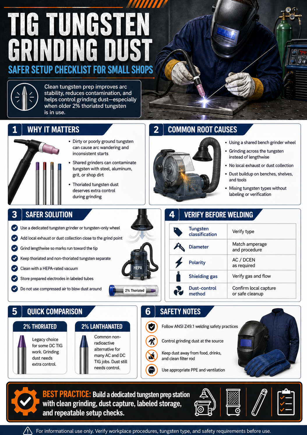
TIG welding often depends on a clean, consistent tungsten point. The problem is that grinding tungsten electrodes can create fine dust, especially when older 2% thoriated tungsten is used. A simple shop setup can reduce exposure, improve point consistency, and keep tungsten prep from contaminating other grinding work.
Key Takeaways
- Dedicated tungsten grinding is cleaner than using a shared bench grinder wheel.
- Thoriated tungsten grinding dust deserves extra control because thorium is radioactive.
- Local exhaust, dust collection, and good housekeeping are more important than speed.
- Lanthanated tungsten is a common non-radioactive alternative for many AC and DC TIG jobs.
- Always verify tungsten type, diameter, current range, and job procedure before changing electrodes.
Problem / Context
A small TIG station may have a good machine, clean filler rod, and proper shielding gas, but still struggle with arc wandering, tungsten inclusions, and inconsistent starts. One overlooked cause is poor tungsten preparation. A shared grinder can load the tungsten with steel, aluminum, abrasive grit, or shop dirt. A poorly controlled grind can also send fine tungsten dust into the work area.
This matters most when grinding thoriated tungsten. AWS safety guidance notes that thoriated tungsten contains thorium and that grinding dust can create an inhalation or ingestion concern. The safest approach is to control dust at the source and avoid casual dry grinding in open shop air.
Root Causes
- Using a shared grinder wheel that has already touched steel, stainless, or aluminum.
- Grinding across the tungsten instead of lengthwise with the electrode axis.
- Using thoriated tungsten without a dust-controlled sharpening process.
- Letting grinding dust accumulate on benches, grinder guards, shelves, or nearby tools.
- Switching tungsten types without checking procedure requirements and arc performance.
- Using the wrong tungsten diameter for the amperage range. Unknown (Verify).
Solution
Set up a dedicated tungsten prep area instead of treating tungsten sharpening as a general grinding task. The setup should include a dedicated grinding surface, controlled dust capture, clear labeling for tungsten types, and a cleaning method that does not blow dust into the air.
- Use a dedicated tungsten grinder, diamond wheel, or tungsten-only grinding attachment.
- Position local exhaust or dust collection close to the grinding point.
- Grind lengthwise so grind marks run toward the electrode tip.
- Keep thoriated tungsten separate from lanthanated, ceriated, or other non-thoriated electrodes.
- Clean with a HEPA-rated vacuum or other approved dust-control method. Do not use compressed air to scatter dust.
- Store prepared tungstens in labeled tubes so clean points do not pick up bench contamination.
Specs / Verification Notes
| Item to Verify | Why It Matters | Status |
|---|---|---|
| Tungsten classification | Confirms whether the electrode is thoriated, lanthanated, ceriated, pure tungsten, or another type. | Unknown (Verify) |
| Tungsten diameter | Diameter must match the machine setting, torch capacity, and job procedure. | Unknown (Verify) |
| Welding polarity | DCEN, AC, and special waveforms may require different tungsten choices and tip geometry. | Unknown (Verify) |
| Shielding gas | Gas type and flow affect arc behavior and tungsten life. | Unknown (Verify) |
| Dust-control method | Open grinding is not the same as local capture or dust collection. | Unknown (Verify) |
Product Section
The following product was checked for a visible Amazon ASIN and cross-checked against manufacturer or welding-supply listings for the same Weldcraft part number. Verify diameter, package quantity, tungsten type, and seller listing before purchase.
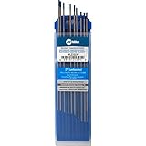
- 2% Lanthanated (Blue) EWLa-2/WL20
- Principal Oxide: 1.8 – 2.2% Lanthanum Oxide
- Non-Radioactive. Best general purpose electrode for both Alternating Current (A/C) or Direct Current (D/C) using inverter or transformer based constant current power sources.
- Good for low-alloyed steels, non corroding steels, aluminum alloys, magnesium alloys, titanium alloys, nickel alloys, copper alloys.
- Good arc starts and stability, medium to high amperage range, low errosion rate.
Last update on 2026-07-14 / Affiliate links / Images from Amazon Product Advertising API
Comparison Table
| Option | Use Case | Dust Concern | Verification Needed |
|---|---|---|---|
| 2% thoriated tungsten | Legacy DC TIG procedures and qualified work where specified | Higher concern when grinding because thorium is present | Confirm procedure requirement and dust controls |
| 2% lanthanated tungsten | Common non-radioactive option for many AC and DC TIG applications | No thorium dust, but grinding dust still needs control | Confirm machine, material, and procedure acceptance |
| Pre-ground tungsten | Repeat work where consistent tip geometry matters | Reduces in-shop grinding | Confirm point angle, flat, diameter, and tungsten type |
| Dedicated tungsten grinder | Shops that sharpen often | Can improve containment if paired with dust control | Confirm collector, wheel type, and electrode size range |
Safety Notes
ANSI Z49.1 covers safety in welding, cutting, and allied processes, including protection of personnel, ventilation, fire prevention, and confined spaces. TIG welding still requires proper helmet shade, eye protection, gloves, clothing, ventilation, and protection from hot metal and ultraviolet radiation.
AWS safety guidance for thoriated tungsten recommends dust-collecting grinders, local exhaust, and respiratory protection where needed to prevent inhalation of dust. Treat grinder dust as a controlled waste stream and follow workplace, local, and regulatory disposal rules.
Do not use compressed air to clean tungsten grinding dust from a bench or grinder. Do not grind thoriated tungsten near food, drinks, open toolboxes, welding coupons, or clean filler rod. Do not assume a non-radioactive tungsten eliminates all respiratory risk; fine grinding dust should still be controlled.
FAQ
Is thoriated tungsten banned?
Not universally. Some workplaces restrict or phase it out, while some qualified procedures still specify it. Verify the job requirement, employer policy, and local rules before use.
Can lanthanated tungsten replace thoriated tungsten?
Often, but not automatically. Lanthanated tungsten is widely used as a non-radioactive alternative, but procedure, machine type, base metal, amperage, and acceptance requirements must be verified.
Should tungsten be sharpened on a belt sander?
Only if the belt is dedicated to tungsten and dust is controlled. A shared belt can contaminate the tungsten and spread dust across the shop.
Why does the arc wander after sharpening?
Common causes include cross-grinding marks, an off-center point, contamination from a shared wheel, an oversized ball, incorrect tungsten diameter, or poor gas coverage.
Is a tungsten grinder required?
No, but a dedicated grinder or controlled sharpening setup can improve consistency and reduce contamination. The key requirement is a clean, repeatable grind with appropriate dust control.
Next Step
Build a small tungsten prep checklist at the TIG bench: tungsten type, diameter, point style, grinding direction, dust control, and storage tube. Keep the checklist with the torch consumables so every tungsten is prepared the same way before welding starts.
Sources Checked
- AWS Safety and Health Fact Sheet No. 27, Thoriated Tungsten Electrodes.
- AWS Safety and Health Fact Sheet No. 2, Radiation.
- ANSI Z49.1:2021, Safety in Welding, Cutting, and Allied Processes.
- Miller Weldcraft product listing for Weldcraft 2% Lanthanated Tungsten WL2332X7.
- Amazon product listing showing ASIN B00VMH8T6M for Miller Weldcraft WL2332X7.
- Cyberweld listing for Weldcraft 2% Lanthanated Tungsten WL2332X7.