Tag: maintenance

  • Troubleshooting Weld Quality Before Replacing Parts

    Tweco MSAK-354 Control Wire Assembly for MIG Guns - High Quality Welding Parts
    “>Tweco MSAK-354 Control Wire Assembly for MIG Guns - High Quality Welding Parts

    If weld quality drops, do not start by replacing parts. Most issues come from process settings, consumables, shielding gas, ground connection, wire feed, or operator technique. Use this weld quality troubleshooting guide to isolate the cause before you spend time and money on parts.

    Key Takeaways

    • Check the process first: voltage, wire feed speed, polarity, gas flow, and work lead condition.
    • Inspect consumables and wire path before replacing gun parts.
    • Confirm the base metal, joint prep, and fit-up are correct.
    • Look for contamination, drafts, or poor shielding before changing hardware.
    • Replace parts only after the problem is isolated.

    Start With the Welding Process

    Many weld defects are process related, not part failures. Verify the following before opening the gun or feeder.

    • Voltage and wire feed speed: Check that settings match the procedure or WPS. Incorrect balance can cause spatter, lack of fusion, burn-through, or cold lap.
    • Polarity: Confirm polarity is correct for the wire type. Incorrect polarity can create unstable arc behavior.
    • Travel speed: Too fast can cause undercut or lack of fusion. Too slow can create excess reinforcement or burn-through.
    • Stickout / CTWD: Excessive stickout can reduce arc stability and increase spatter.

    Check Shielding Gas First

    Shielding gas problems can look like bad consumables or a failing gun. Verify gas setup before replacing parts.

    • Gas type: Confirm the gas matches the wire and procedure. Unknown (Verify).
    • Flow rate: Set the flow according to the application and nozzle size. Unknown (Verify).
    • Leaks: Inspect hoses, fittings, and the gun connection for leaks.
    • Drafts: Air movement around the weld area can break shielding and cause porosity.
    • Nozzle condition: Spatter buildup or damage can disturb gas coverage.

    Inspect the Wire Feed System

    Wire feed instability can create arc fluctuation, burnback, and inconsistent bead shape.

    • Drive rolls: Check for correct size and wear. Unknown (Verify).
    • Drive pressure: Too loose causes slipping. Too tight can deform wire.
    • Liner condition: A dirty or worn liner can cause feeding issues and inconsistent current transfer.
    • Spool tension: Excess drag can cause jerky feed.
    • Wire quality: Rust, contamination, or kinks can create feeding problems.

    Review Consumables and Contact Surfaces

    Before replacing a control wire assembly or gun component, inspect the basic wear items first.

    • Contact tip: A worn, oversized, or blocked tip can cause erratic arc behavior.
    • Nozzle: Spatter buildup can restrict gas coverage and reduce visibility.
    • Diffuser / retaining parts: Loose or damaged components can affect alignment and shielding.
    • Work clamp: A poor ground connection can cause arc instability and poor penetration.

    Check the Base Metal and Joint Prep

    Weld quality problems often start at the joint.

    • Surface contamination: Oil, paint, rust, mill scale, and moisture can cause porosity and fusion problems.
    • Joint fit-up: Excessive gap or poor alignment can lead to inconsistent bead profile.
    • Material thickness: Unknown (Verify) if the selected process and settings are suitable.
    • Preheat / interpass temperature: Unknown (Verify) where required by procedure.

    Common Symptoms and What to Check

    • Porosity: Check gas coverage, leaks, contamination, drafts, and nozzle condition.
    • Excess spatter: Check voltage, wire feed speed, polarity, stickout, and contact tip wear.
    • Wire burnback: Check wire feed speed, tip condition, liner drag, and drive roll pressure.
    • Erratic arc: Check ground connection, liner, contact tip, gas flow, and spool drag.
    • Lack of fusion: Check voltage, travel speed, joint prep, and cleaning.

    When a Part Replacement Makes Sense

    Replace parts only after the problem follows the component or shows clear wear. For MIG gun control and feed-related issues, the Tweco MSAK-354 Control Wire Assembly for MIG Guns may be a relevant replacement option when the original assembly is damaged or no longer performing as expected. Use the part only if it matches the existing setup. Compatibility is Unknown (Verify).

    Tweco MSAK-354 Control Wire Assembly for MIG Guns - High Quality Welding Parts

    Tweco MSAK-354 Control Wire Assembly for MIG Guns – High Quality Welding Parts

    Introducing the MSAK-354 Control Wire Assembly, a premium component designed to enhance your MIG welding experience. This high-quality control wire assembly is manufactured by Tweco, a reputable name in the welding industry. Precision-engineered, the MSAK-354 provides reliable performance and durability that meets the demands of both professional welders and DIY enthusiasts. The MSAK-354 is essential for ensuring…

    View at Arc Weld Store

    Do not assume the control wire assembly is the cause of poor weld quality until you have checked process settings, gas coverage, wire feed, and consumables.

    Support Workflow for Maintenance Teams

    1. Document the defect type: porosity, spatter, lack of fusion, undercut, burnback, or instability.
    2. Verify machine settings against the procedure or WPS.
    3. Inspect gas, wire feed, liner, tip, nozzle, and work clamp.
    4. Clean the joint and verify fit-up.
    5. Run a test weld after each change so you know what corrected the issue.
    6. Replace parts only after the fault is isolated.

    Safety Notes

    • Lock out and tag out equipment before inspecting internal components where required by site rules.
    • Allow hot parts to cool before handling.
    • Wear proper PPE when checking weld equipment and performing test welds.
    • Do not bypass safety interlocks or use damaged cables, connectors, or gas hoses.
    • Use ventilation and follow your shopโ€™s fume control procedures.

    FAQ

    Why does the weld look bad if the machine seems fine?
    Weld appearance can be affected by shielding gas, contamination, wire feed instability, joint prep, or technique. A machine can operate normally while the process is still out of control.

    Should I replace the gun first?
    No. Check the consumables, wire path, work clamp, gas delivery, and settings first. Replace the gun or its components only after you isolate the fault.

    Can a bad ground cause porosity?
    Yes. A poor work connection can contribute to unstable arc behavior and poor bead quality.

    What is the fastest way to narrow it down?
    Make one change at a time and run a short test weld. That is the most reliable way to separate process issues from hardware issues.

    Sources Checked

    • ArcWeld product information for Tweco MSAK-354 Control Wire Assembly for MIG Guns
    • Internal drafting requirements provided for this article
  • Exothermic Cutting Rod Will Not Stay Lit

    Arcair 94-463-032, Slice 3/8" Conversion Kit
    “>Arcair 94-463-032, Slice 3/8" Conversion Kit

    If an exothermic cutting rod will not stay lit, start with oxygen delivery, rod condition, and starting technique. Most ignition problems come from inconsistent gas flow, a worn consumable, or a poor start angle.

    Key Takeaways

    • Confirm oxygen flow at the torch and at the source before blaming the rod.
    • Inspect the rod for moisture, damage, or contamination.
    • Use a firm start and keep the rod tip engaged long enough to establish the burn.
    • Verify the setup matches the rod and torch system in use.
    • If the issue repeats, replace worn consumables and inspect the torch setup.

    Troubleshooting Support

    When an exothermic cutting rod not staying lit becomes repeatable, work through the setup in order. Do not change multiple variables at once.

    1) Check oxygen supply technique

    Use a steady oxygen supply. Low flow, blocked passages, or rapid trigger changes can extinguish the cut as soon as the rod tries to establish the burn. Confirm the oxygen valve, hose, and torch path are open and operating normally.

    2) Inspect the rod condition

    Rod condition matters. A rod that is damp, bent, damaged, or contaminated may not stay lit. Store consumables dry and handle them cleanly. If the rod coating or end condition looks abnormal, discard it and try a new rod.

    3) Verify the starting technique

    The rod needs a clean, deliberate start. Hold the correct position, strike consistently, and keep the oxygen engaged as required by the process. If the rod is lifted too soon or the start is inconsistent, the burn can drop out.

    4) Check for setup mismatch

    Make sure the torch, consumable, and conversion hardware match the process being used. If the system has been modified, compatibility is Unknown (Verify) until confirmed by the equipment documentation.

    5) Look for wear in the torch path

    Restricted flow, damaged seals, or worn internal components can interrupt oxygen delivery. Inspect the torch and related parts for damage, dirt, or blockage.

    Support Section: Parts and Conversion Hardware

    If you are troubleshooting a persistent ignition problem and the setup uses compatible Arcair hardware, the related support article may help compare symptoms and causes.

    For conversion-related setup checks, one available part is:

    • Arcair 94-463-032, Slice 3/8" Conversion Kit โ€” Use when the conversion kit is confirmed to match the torch and cutting system. Compatibility details beyond the provided product listing are Unknown (Verify).

    Product link:

    Arcair 94-463-032, Slice 3/8" Conversion Kit

    Arcair 94-463-032, Slice 3/8" Conversion Kit

    Introducing the Arcair 94-463-032, Slice 3/8" Conversion Kit, an essential addition to your cutting tool arsenal. This conversion kit is designed to enhance the performance of your existing cutting equipment, ensuring precision and efficiency in your cutting tasks. The Arcair 94-463-032 is specifically engineered to fit seamlessly with compatible models, providing a reliable solution for your cutting needs. Whethe…

    View at Arc Weld Store

    Safety Notes

    • Keep flammables away from the cutting area.
    • Wear appropriate eye, hand, and body protection for exothermic cutting.
    • Do not inspect or service oxygen equipment while pressurized unless the procedure allows it and the system is made safe.
    • Replace damaged consumables instead of forcing them to work.
    • If you smell gas, hear leaks, or see unstable flame behavior, stop and isolate the system.

    FAQ

    Why does the rod light and then go out?

    Common causes are weak oxygen flow, poor starting technique, or a rod that is damp or damaged.

    Can I keep using a rod that will not stay lit after several tries?

    No. If ignition remains unstable, replace the rod and inspect the torch setup. Repeated failed starts can indicate contamination or a supply problem.

    Should I adjust oxygen flow first or replace the rod first?

    Check oxygen delivery first, then test with a fresh rod. That sequence helps isolate the fault faster.

    Is the Arcair conversion kit a guaranteed fix?

    No. The conversion kit is a hardware option, not a diagnosis. Use it only if the system compatibility is confirmed. Otherwise, compatibility is Unknown (Verify).

    Sources Checked

    Related Weld Support Guides

  • Why Your MIG Welder Sputters and Pops: Diagnosis and Fix

    Your MIG welder sputters, pops, or cuts out mid-weld. The arc is unstable, the weld looks rough, and you’re losing time troubleshooting. This guide walks you through the most common causesโ€”and how to fix each one in under 30 minutes.

    Key Takeaways

    • Sputtering is usually caused by worn contact tips, dirty nozzles, or poor ground connections (not the machine itself)
    • Most fixes are free or cost under $20
    • Replace contact tips every 50โ€“100 hours of welding for consistent performance
    • Clean your nozzle and check your ground clamp before buying new parts
    • A worn contact tip can cause arc instability even on a quality machine

    Quick Diagnosis

    What you’ll see:

    • Arc pops or crackles during welding
    • Wire feed seems inconsistent
    • Spatter builds up on the nozzle and tip
    • Weld bead looks rough or has gaps
    • Machine may cut out briefly, then restart

    Most likely causes (ranked by frequency):

    1. Worn or damaged contact tip (most common)
    2. Spatter buildup on nozzle or tip
    3. Poor ground connection or dirty work clamp
    4. Wire speed set too high or too low
    5. Gas flow rate too low or regulator issue
    6. Kinked or damaged gun liner

    Safety Notes

    • PPE:ย Wear ANSI Z87.1-rated helmet with appropriate shade (typically #10โ€“#12 for MIG), leather gloves, and flame-resistant clothing. Keep helmet DOWN during all welding.
    • Ventilation:ย Ensure adequate fume extraction. MIG welding produces COโ‚‚ and metal fumesโ€”use a fume hood or work in well-ventilated space.
    • Electrical:ย Disconnect the welder from power before inspecting the gun, liner, or contact tip.
    • Gas:ย Check regulator for leaks before starting. Do not exceed manufacturer’s recommended gas flow rate.

    Step-by-Step Troubleshooting

    Step 1: Inspect the Contact Tip (Free)

    • Remove the nozzle from your MIG gun.
    • Look at the contact tip (the small copper piece at the end of the gun).
    • If it’s worn, pitted, or has a flat spot instead of a tapered point, replace it.
    • Why:ย A worn tip creates poor electrical contact, causing arc instability and sputtering.

    Step 2: Clean the Nozzle (Free)

    • Remove the nozzle (usually a threaded brass or ceramic piece).
    • Use a wire brush or old contact tip to scrub away spatter buildup inside and outside.
    • Reinstall and test.
    • Why:ย Spatter on the nozzle blocks gas flow and creates electrical resistance, destabilizing the arc.

    Step 3: Check Your Ground Clamp (Free)

    • Inspect the ground clamp on your work piece. Look for rust, paint, or corrosion.
    • Clean the contact surface with a wire brush or file.
    • Ensure the clamp is tight and making solid metal-to-metal contact.
    • Why:ย A poor ground path increases electrical resistance, causing the arc to be unstable.

    Step 4: Verify Wire Speed and Voltage (Free)

    • Check your machine’s wire speed and voltage settings against the manufacturer’s chart for your wire type and thickness.
    • If wire speed is too high, the tip can overheat and wear faster. If too low, the arc may be weak.
    • Adjust to the middle of the recommended range and test.
    • Why:ย Incorrect settings stress the contact tip and create inconsistent arc conditions.

    Step 5: Check Gas Flow Rate (Free)

    • Locate your regulator and check the flow rate (usually 15โ€“25 CFH for MIG).
    • If the gauge reads below 15 CFH, increase the flow slightly.
    • If you suspect a leak, apply soapy water to all connectionsโ€”bubbles indicate a leak.
    • Why:ย Low gas flow allows air into the weld, causing porosity and arc instability. Leaks reduce shielding.

    Step 6: Inspect the Gun Liner (Free)

    • Remove the wire spool and pull the wire out of the gun.
    • Look through the gun liner (the tube inside the gun that guides the wire).
    • If you see kinks, cracks, or heavy wear, the liner may be restricting wire feed.
    • Why:ย A damaged liner causes friction, which can jam the wire and destabilize the arc.

    Fix Options (Ranked)

    Option 1: Adjustment (Free)

    • Clean nozzle and ground clamp.
    • Verify wire speed and gas flow settings.
    • Test weld.
    • When to use:ย If sputtering started recently and your machine is less than 5 years old.

    Option 2: Replace Contact Tip (~$5โ€“$15)

    • Order a replacement contact tip that matches your gun type and wire size (e.g., 0.035″ for standard MIG).
    • Remove the old tip, install the new one, and test.
    • When to use:ย If the tip is visibly worn, pitted, or you’ve been welding for 50+ hours since the last replacement.

    Option 3: Replace Gun Liner (~$15โ€“$40)

    • If the liner is kinked or damaged, order a replacement liner kit for your gun model.
    • Follow the manufacturer’s installation instructions.
    • When to use:ย If you’ve ruled out the tip and nozzle, and the wire feed feels sluggish.

    Option 4: Equipment Upgrade (if applicable)

    • If your machine is 10+ years old and you’ve replaced the tip and liner, consider upgrading to a newer machine with better arc stability.
    • When to use:ย Only after all consumables and settings have been checked.

    Recommended Fix: Replace Your Contact Tips

    A worn contact tip is the #1 cause of sputtering. Copper tips wear down with every weldโ€”the arc erodes the tapered point, creating a flat or pitted surface. Once worn, the tip can’t deliver consistent electrical contact to the wire, and your arc becomes unstable.

    Why this works:

    • A fresh contact tip restores the precise tapered geometry needed for stable arc initiation.
    • Copper’s high conductivity ensures reliable electrical transfer.
    • New tips prevent spatter buildup and reduce nozzle fouling.

    When to use it:

    • Your contact tip is visibly worn or pitted.
    • You’ve been welding for 50โ€“100 hours since the last replacement.
    • You’ve cleaned the nozzle and ground clamp, but sputtering persists.

    When NOT to use it:

    • If your nozzle is heavily fouled with spatterโ€”clean that first (it’s free).
    • If your ground clamp is loose or corrodedโ€”fix that before replacing the tip.
    • If your wire speed or voltage is way offโ€”adjust settings first.

    What to check before buying:

    • Confirm your gun type (e.g., Lincoln Magnum 100L, Miller M25, Tweco Mini).
    • Match the wire size (0.030″, 0.035″, or 0.045″).
    • Buy a multi-pack (20โ€“30 tips) so you always have spares on hand.
    • Look for tips with at least 4+ stars and 100+ reviews.
    • Verify the tip is copper (not steel) for best conductivity.

    No products found.

    Comparable Options

    If you need tips for a different gun type, check these:

    Common Mistakes

    • Using the wrong wire size tip.ย A 0.030″ tip won’t work with 0.035″ wire. Check your machine manual or gun label.
    • Not replacing tips regularly.ย Tips wear outโ€”don’t wait until sputtering is severe. Replace every 50โ€“100 hours.
    • Ignoring the nozzle.ย Spatter buildup on the nozzle blocks gas and causes arc instability. Clean it every few welding sessions.
    • Assuming the machine is broken.ย 90% of sputtering issues are consumables or settings, not the welder itself.
    • Over-tightening the contact tip.ย Hand-tight is enough. Over-tightening can crack the tip or damage the gun threads.

    FAQ

    Q: How often should I replace my contact tip? A: Every 50โ€“100 hours of welding, or sooner if you notice visible wear. A worn tip costs you time and material in bad welds.

    Q: Can I clean and reuse a contact tip? A: No. Once a tip is pitted or flattened, cleaning won’t restore its geometry. Replace it.

    Q: Why does my tip wear out so fast? A: High wire speed, incorrect voltage, or poor shielding gas flow accelerates wear. Check your settings and gas flow rate.

    Q: What’s the difference between copper and steel contact tips? A: Copper conducts electricity better and lasts longer. Steel tips are cheaper but wear faster and create more spatter. Use copper.

    Q: Can a bad ground clamp cause sputtering? A: Yes. A loose or corroded ground clamp increases electrical resistance, destabilizing the arc. Always ensure solid metal-to-metal contact.

    Next Steps

    1. Clean your nozzle and ground clamp nowย โ€” this is free and fixes 30% of sputtering issues.
    2. Check your wire speed and gas flowย โ€” verify they match your machine’s recommended settings for your wire type.
    3. Order replacement contact tipsย โ€” keep a multi-pack on hand so you’re never without spares.
    4. Read our related troubleshooting guides:

    For more welding fixes and gear options, see our full resource page: https://blog.weldsupportparts.com/links/

  • Best Plasma Cutter Consumables for Heavy Dross

    If your plasma cuts are leaving heavy bottom dross, the fastest โ€œreal fixโ€ is often replacing worn consumablesโ€”especially the nozzle/tip and electrode. Below are practical replacement options and what to look for so you get clean cuts again without wasting time grinding.

    Not sure this is your issue? [See the full troubleshooting guide โ†’ {PROBLEM POST TITLE & URL}]

    WHERE TO BUY (ABOVE THE FOLD โ€” REQUIRED)

    No products found.

    Key Takeaways:

    • Replaceย nozzle/tip + electrode as a setย when cut quality drops
    • Heavy dross gets worse withย eroded nozzle orificeย andย pitted electrodes
    • Use the correctย drag shield/tipย if you drag cut
    • Air moisture and low pressure can ruin new consumables fastโ€”fix air first

    Comparison Table:

    ModelKey SpecsBest For
    Hypertherm 851510 Essential Handheld KitIncludes electrodes/nozzles/drag shield (kit)Stocking common wear items for Powermax45 XP handheld
    Hypertherm 220941 (45A nozzle)45A cutting nozzle (part)Replacing a worn nozzle causing dross/bevel
    Hypertherm 220842 (electrode)Electrode (part)Restoring arc stability when electrode is pitted
    Drag shield (model-specific)Shield for drag cutting (part)Drag cutting without destroying tips

    Copy table

    Product 1 โ€” Hypertherm 851510 Essential Handheld Consumable Kit

    Short description: A genuine consumables kit that bundles the common wear items so you can reset cut quality quickly.
    Key specs (manufacturer verified): Kit for Powermax45 XP essential handheld, 45A cutting; Hypertherm part number 851510. (Contents vary by kit listingโ€”verify before publishing.)
    Best for: Users who want a single purchase to refresh consumables and reduce downtime.
    ArcWeld link: N/A
    Amazon:

    No products found.

    Product 2 โ€” Replace the Nozzle/Tip (model-specific)

    Short description: The nozzle orifice shape directly affects arc focus and dross. If itโ€™s out-of-round, cut quality will not recover.
    Key specs: Unknown (Verify)
    Best for: Heavy bottom dross, rough edge, increased bevel after previously clean cuts.
    ArcWeld link: N/A
    Amazon:

    No products found.

    MID-POST CTA (REQUIRED):
    Still deciding? Compare these options below.

    No products found.

    Product 3 โ€” Replace the Electrode (model-specific)

    Short description: A pitted electrode can destabilize the arc and accelerate nozzle wear.
    Key specs: Unknown (Verify)
    Best for: Arc instability, rapid consumable wear, inconsistent cut quality.
    ArcWeld link: N/A
    Amazon:

    No products found.

    Product 4 โ€” Drag Shield / Standoff Guide (model-specific)

    Short description: If you drag cut without the correct shield, you can chew through tips and create inconsistent heightโ€”both drive dross.
    Key specs: Unknown (Verify)
    Best for: Handheld drag cutting on plate where consistent height is hard to maintain.
    ArcWeld link: N/A
    Amazon:

    No products found.

    TOP PICK CALLOUT:
    Top pick (best overall): Hypertherm 851510 kit โ€” itโ€™s the simplest way to reset multiple wear points at once (nozzle + electrode + shield components), which is exactly what heavy dross usually indicates.

    Buying Guide: How to Choose

    • Compatibility first:ย Match consumables to your exact torch and amperage range (verify torch series/model).
    • Replace as a set:ย If the nozzle is worn, the electrode is often not far behindโ€”pair replacement reduces repeat issues.
    • Drag vs standoff:ย Buy the correct shield/tip setup for how you actually cut.
    • Air quality:ย If you donโ€™t drain water and stabilize pressure, youโ€™ll burn through new consumables quickly.

    FAQ

    1) Does heavy bottom dross mean Iโ€™m cutting too slow?
    Often, yesโ€”but worn consumables and incorrect height can create the same symptom.

    2) Should I replace just the nozzle or the electrode too?
    If cut quality dropped noticeably, replace both (common practice to restore arc shape).

    3) Why did my cuts get worse overnight?
    Check air moisture/pressure first, then inspect consumables for erosion/pitting.

    4) Can I drag cut with any tip?
    Noโ€”use consumables designed for drag cutting or maintain proper standoff.

    Safety Notes

    Plasma cutting produces hot slag and UV/IR radiation. Wear gloves and ANSI Z87.1 eye protection; use a face shield when chipping dross and keep bystanders protected.

  • Best Welding Helmet Replacement Lenses for Clear Visibility

    If your weld puddle looks hazy or washed out, your helmet lens is usually the problemโ€”not your settings. Replacing the outer cover lens is the fastest, cheapest fix (and it’s a consumable in any busy shop).

    Not sure this is your issue? See the full troubleshooting guide:Why You Can’t See Your Weld Pool (And How to Fix It)

    No products found.

    Key Takeaways

    • Start with the outer cover lens (the clear protective lens). It takes the scratches and spatter so your ADF doesn’t have to.
    • If you weld MIG or flux-core, keep a spare pack on hand and swap lenses as soon as visibility drops.
    • Buy OEM lenses when possible (Lincoln/Miller/3M/Jackson). Aftermarket quality varies.
    • Verify your helmet’s lens size/model before ordering.
    • Replace any lens that’s cracked, deeply scratched, or heat-warped.

    Quick Comparison

    ProductWhat It IsFitsBest For
    Lincoln KP2898-1Outer cover lens (5-pack)Viking 3350/850S/750SLincoln owners, high spatter
    Miller 216326Outer cover lens (5-pack)Digital Elite / Elite series (verify model)Miller owners, daily shop use
    3M Speedglas 9100 outer cover lensOuter cover lens (pack size varies)Speedglas 9100 series (verify)Speedglas owners

    Top Picks (Outer Cover Lenses)

    1) Lincoln KP2898-1 (VIKING Outside Cover Lens)

    OEM outside cover lenses for Lincoln Viking helmets. This is the simplest fix when your view is cloudy from scratches, spatter, or grinding dust.

    Key specs: Unknown (Verify)

    Best for: Lincoln Viking 3350/850S/750S users who want a quick visibility reset.

    Buy:

    No products found.


    2) Miller 216326 (Front Lens Cover)

    OEM front cover lenses for Miller helmets. If you’re running MIG all day, these are a low-cost consumable that keeps your view crisp.

    Key specs: Unknown (Verify)

    Best for: Miller Digital Elite/Elite-series users (confirm fitment before ordering).

    Buy:

    No products found.


    Still deciding? Compare these options below.

    No products found.


    3) 3M Speedglas 9100 Outer Cover Lens (Verify exact model)

    Speedglas lenses are helmet-specific. If you’re on a 9100 series hood, start by replacing the outer cover lens before assuming your auto-darkening filter is failing.

    Key specs: Unknown (Verify)

    Best for: Speedglas 9100 series owners who want OEM clarity.

    Buy:

    No products found.


    Top Pick Callout

    Top pick (best overall for most welders):OEM outer cover lenses for your exact helmet model.

    Reason: outer lenses are the part that gets destroyed first, and replacing them restores visibility immediately with minimal cost.

    Buying Guide: How to Choose

    1. Confirm your helmet model (inside label or manual). Don’t guess.
    2. Confirm lens type: outer cover lens vs inner lens vs ADF. This page is for outer cover lenses.
    3. Check the pack quantity, so you’re not re-ordering every month.
    4. Replace on a schedule if you weld daily (or whenever you notice haze).

    FAQ

    Do I need to replace the auto-darkening filter (ADF) if I can’t see?

    Usually no. Replace the outer cover lens first. If the view is still hazy, then inspect the ADF and inner lens.

    How often should I replace the outer cover lens?

    As needed. In high-spatter work, it can be monthly. In cleaner TIG work, it can last much longer.

    Will any 4.5″ x 5.25″ lens fit my helmet?

    Not always. Many helmets share sizes, but fitment varies by brand and series. Verify before ordering.

    Why does my lens look cloudy right after I replace it?

    Check for protective film you forgot to peel, dust inside the helmet, or a scratched inner lens.
    Safety Notes

    • Wear safety glasses under the hood.
    • Replace lenses that are cracked or heavily scratched.
    • Use ANSI Z87.1-rated eye/face protection.
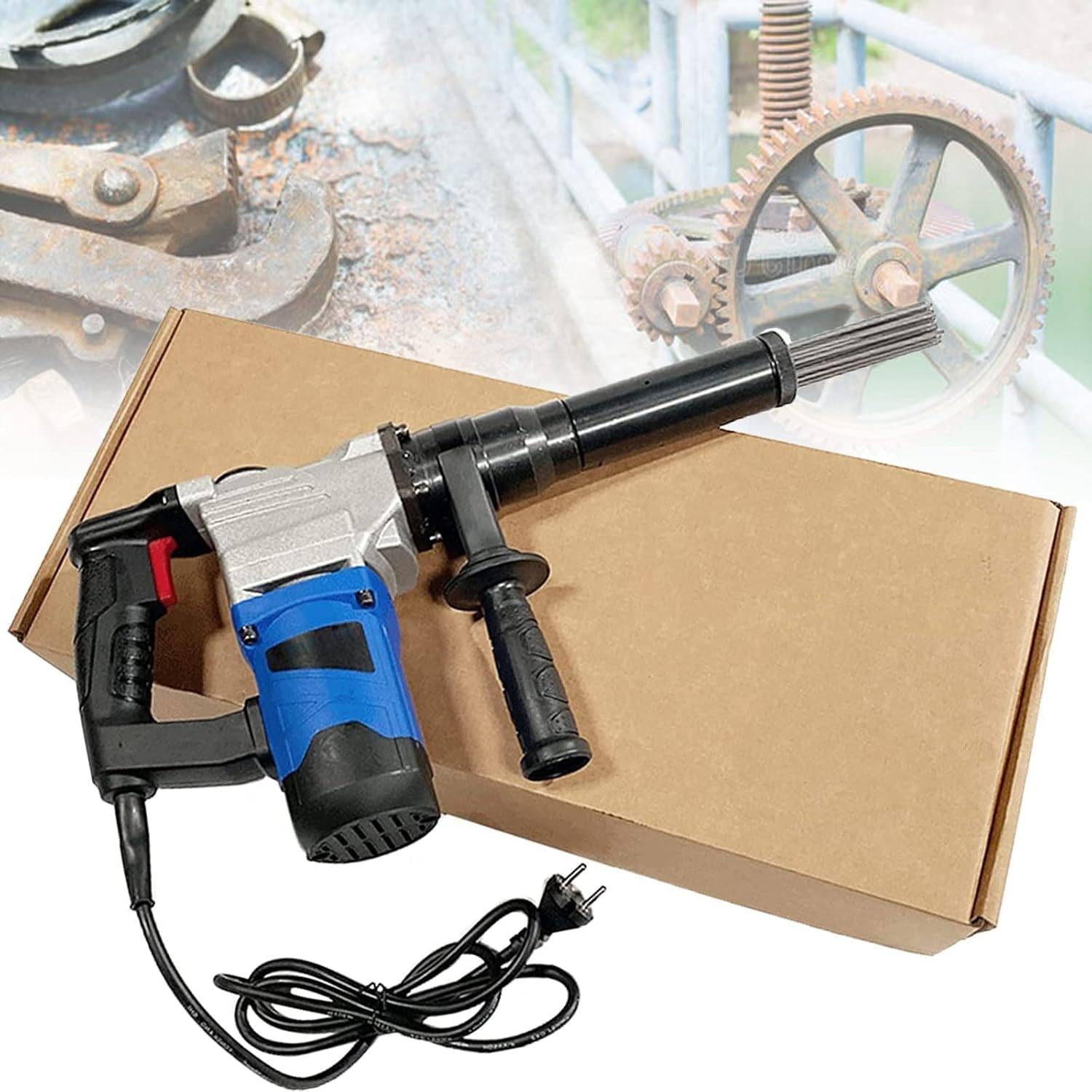
  • Needle Scaler for Welding Slag and Rust: When a Handheld Electric Needle Scaler Makes Sense

    Needle Scaler for Welding Slag and Rust: When a Handheld Electric Needle Scaler Makes Sense

    If youโ€™re cleaning weld slag, heavy rust, or old coatings, a needle scaler can be the right toolโ€”especially when a grinder is too aggressive or you need to get into texture and corners.

    This post is a practical buying guide built around one handheld electric needle scaler listing, with a focus on what to compare before you spend money and what to verify in the listing.

    Key Takeaways

    • Needle scalers are for chipping/peening actionโ€”good for slag, rust, and coatings in tight areas.
    • Electric models can be convenient, but you still need to verify voltage, duty cycle, and replacement needle availability.
    • Expect noise, vibration, and flying debrisโ€”PPE is not optional.
    • For flat surface blending, abrasives often finish cleaner than needle scaling.

    Product (Verified)

    No products found.

    What a needle scaler is best at A needle scaler uses multiple steel needles that rapidly strike the surface. That impact action is useful when you need to:

    • Break loose slag and spatter residue
    • Knock off flaking rust and scale
    • Strip coatings in uneven areas
    • Work around edges, corners, and textured surfaces

    Itโ€™s usually not the best tool for:

    • Final cosmetic finishing (it can leave a peened texture)
    • Precision prep on thin sheet (risk of distortion/marking)
    • Quiet/low-vibration work (itโ€™s the opposite)

    Performance & Use A needle scaler is a โ€œget it offโ€ tool, not a โ€œmake it prettyโ€ tool. In a welding workflow, itโ€™s often used before switching to abrasives for blending, or before repainting/coating.

    What to compare before you buy

    • Voltage and plug requirements (verify your shop power matches the listing)
    • Duty cycle / run time limits (many handheld tools overheat if pushed)
    • Replacement needles availability and cost (consumable item)
    • Tool weight and vibration control (fatigue matters)
    • Intended use case: slag/rust/coatings vs fine finishing (donโ€™t mix expectations)

    Comparable Amazon picks (optional)

    How to use a needle scaler without making a mess (or damaging work)

    • Start with light pressure and let the needles do the work
    • Keep the tool moving; donโ€™t dwell in one spot
    • Use it for removal, then switch to abrasives if you need a smoother finish
    • Plan containment: chips and debris go everywhere

    Safety notes (quick) Needle scaling throws debris and is loud. At minimum: safety glasses + face shield, hearing protection, and gloves. If youโ€™re removing coatings, assume unknown dust until proven otherwiseโ€”use ventilation and appropriate respiratory protection per your shop policy.

    Where to Buy (Amazon) GTANND Electric Needle Scaler listing (ASIN: B0D9N7RLDK)
    https://www.amazon.com/GTANND-Electric-Derusting-Hand-Held-Portable/dp/B0D9N7RLDK?tag=weldsupport-20

  • Watch with Prime Video