Arc Air 94-433-193 Insulator Assembly for K2000/K3000 Carbon Arc Gouging Torch – Durable & Reliable
$29.71
In Stock
View Product
$29.71
In Stock
View Product
If a carbon arc gouging rod will not strike, start with the basics: current path, air supply, holder contact, and the rod itself. Most no-strike complaints come from loss of contact, poor clamp connection, low air, or damaged insulation at the torch or holder.
A gouging rod needs a solid electrical return path. Loose clamp jaws, rust, paint, scale, or a bad cable lug can stop the arc from starting.
If output is too low, the rod may only scratch without striking. Confirm the machine is set for gouging, not a low-current welding setting.
Carbon arc gouging uses air to clear the groove. Low or blocked air will not always prevent striking, but it can make the process unstable and look like a starting fault.
A damaged rod end, heavy oxidation, or the wrong diameter can prevent reliable arc initiation.
Poor contact inside the holder can stop current from reaching the rod. Check for looseness, burnt jaws, carbon buildup, or damaged internal parts.
Damaged insulation can cause erratic current flow, especially on K2000/K3000-style equipment. If the insulator assembly is cracked, carbon tracked, or heat damaged, replace it.
If the basics check out, isolate the fault by changing one item at a time.
If the setup begins striking after a part change, the removed part is likely the failure point.
If the insulator assembly is damaged on a compatible torch, use the listed replacement below. Compatibility beyond the stated torch models is Unknown (Verify).
Introducing the Arc Air 94-433-193 Insulator Assembly, a crucial component designed to enhance the performance of your K2000 and K3000 carbon arc gouging torches. This high-quality insulator assembly is essential for ensuring optimal functioning and reliability during your gouging tasks. The Arc Air insulator assembly is engineered to withstand the demanding conditions of arc gouging. It is crafted with durable ma…
View at Arc Weld StoreRelated reading:
Usually poor contact, low current, a bad work clamp, or a damaged rod end.
It can make the process unstable, but most no-strike problems are first caused by electrical contact or machine output issues.
Replace it if it is cracked, burned, carbon tracked, or loose. Use a known-compatible part only; otherwise, compatibility is Unknown (Verify).

$360.80
In Stock
View Product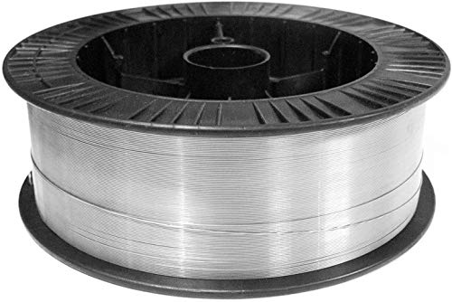
Stainless steel can lose corrosion resistance after welding when the weld area is overheated, not cleaned properly, or matched with the wrong filler. The base metal may still be stainless, but the weld zone can become more vulnerable to rust staining, pitting, and premature attack.
Stainless steel depends on a passive chromium oxide layer for corrosion resistance. Welding disrupts that layer. If the weld overheats, oxygen reacts with the surface and creates heat tint. That discoloration indicates oxide formation and possible chromium depletion near the surface.
When chromium is tied up in oxide scale, the surface cannot protect itself as effectively. In corrosive service, that area can fail before the surrounding base metal.
Heat tint should be treated as a corrosion-control issue. Removing it helps restore surface performance, but removal method matters. Use only cleaning methods approved for the material and the job. Aggressive grinding can damage the surface and create more contamination.
If the application requires higher corrosion resistance, pickling and passivation may be specified. Exact chemistry and process requirements are application-dependent. Unknown (Verify).
For stainless support work, filler selection must be checked before the weld is made. A mismatch may not show immediately, but it can affect long-term performance in service.
For general stainless MIG work, the listed ArcWeld product is:
Discover the premier choice in welding materials with Washington Alloy 33 lb. Spool MIG Wire. This high-quality stainless steel MIG wire is designed specifically for exceptional performance in various welding applications. With a diameter of .035 inches, this 308L stainless steel wire offers the perfect balance of strength and versatility. Crafted for professional welders and DIY enthusiasts alike, Washington Allo…
View at Arc Weld StoreUse the filler only when it matches the job specification and base metal requirements. If the stainless grade or service condition is not confirmed, stop and verify before production welding.
If a weld already shows rust staining or early corrosion, check these points in order:
When corrosion resistance matters, buy and stage stainless wire by verified alloy family, not by wire diameter alone. Keep stainless consumables separated from carbon steel consumables. Label storage clearly. Cross-contamination is a common shop-floor failure mode.
For repeat jobs, document the base metal grade, filler, shielding gas, cleaning method, and post-weld treatment so the same defect does not repeat.
No. But it does indicate oxidation and reduced corrosion margin. The service environment decides how serious it is.
Sometimes. If the damage is only surface oxidation, cleaning and passivation may help. If the weld metal or base metal has already been attacked, repair may be required. Unknown (Verify).
No. ER308L is common for some austenitic stainless applications, but filler choice depends on base metal grade and service conditions. Verify the specification before use.
The weld zone sees heat tint, dilution, and possible contamination. That area often has the weakest passive layer and is the first place corrosion appears.
Drill bit chatter in steel usually points to a setup problem, a tool condition problem, or both. The bit is not cutting smoothly, so it starts to bounce, squeal, or leave a rough hole. In steel, the most common causes are incorrect speed, too little feed pressure, poor workholding, a dull bit, or a walking start point.
Loose material is one of the fastest ways to create chatter. If the part can move, flex, or vibrate, the bit will not stay engaged.
Excess RPM can make the bit skim the surface instead of cutting cleanly. That increases heat and vibration.
Too little pressure lets the cutting edges bounce across the material. The bit needs enough feed to stay engaged.
A dull, chipped, or uneven bit can cause chatter even in a solid setup. Check the cutting edges and point geometry.
If the bit walks before it bites, it can start vibrating as soon as it touches the surface.
Packed chips increase rubbing and heat. That can turn into chatter fast, especially in deeper holes.
Runout, worn bearings, loose chucks, or flex in the setup can amplify chatter. If the machine itself is unstable, the bit cannot cut smoothly.
If you are troubleshooting repeated chatter, it helps to rule out a worn or poor-quality bit. A fresh, properly sized bit is easier to evaluate than a damaged one.
The Triumph Twist Drill T17HD 1/16-Inch to 1/2-Inch Drill Set by 64ths, Thunderbit Premium High Speed Steel is available as a general drill set option for steel, wood, and plastic applications. Specific steel grade limits, coating details, and exact performance data are Unknown (Verify).
[ArcWeld product box: Unearth professional-grade performance with the Triumph Twist Drill T17HD Drill Set, a must-have for any serious tradesperson or DIY enthusiast. This exceptional drill set covers sizes from a precise 1/16-inch to a robust 1/2-inch in increments of 64ths, equipping you with a versatile array of drill bits for all your projects. Ideal for drilling into wood, metal, or plastic, these premium high-speed steel bits pro…
]
Triumph Twist Drill T17HD 1/16-Inch to 1/2-Inch Drill Set by 64ths, Thunderbit Premium High Speed Steel
That usually means the bit is walking, the surface mark is weak, or the feed pressure is too light at entry. A center punch and a slower, more controlled start often help.
Chip buildup, heat, and bit flex become more important as depth increases. Peck drilling and chip clearing usually help.
Yes. A dull bit cuts poorly and tends to rub or bounce instead of biting cleanly.
In most steel drilling cases, slower speed is the first adjustment. If the bit is only rubbing, you may also need more steady feed pressure.
Cutting fluid often helps reduce heat and improve chip flow, but exact recommendations depend on the steel type, drill type, and drilling method. Verify per procedure.
Unearth professional-grade performance with the Triumph Twist Drill T17HD Drill Set, a must-have for any serious tradesperson or DIY enthusiast. This exceptional drill set covers sizes from a precise 1/16-inch to a robust 1/2-inch in increments of 64ths, equipping you with a versatile array of drill bits for all your projects. Ideal for drilling into wood, metal, or plastic, these premium high-speed steel bits pro…
View at Arc Weld StoreIf a cut-off wheel wearing fast is a recurring problem, the issue is usually not the wheel alone. Excess pressure, wrong wheel type, side loading, poor RPM matching, and poor technique all shorten wheel life. In many cases, the wheel is being used outside its intended cutting range.
If you have to force the cut, stop and check the setup. A cut-off wheel should remove material with steady, moderate feed. Heavy pressure overheats the abrasive, closes the cut, and can glaze or wear the wheel quickly.
Wheel bond, grit, and thickness affect life. A wheel that works acceptably on mild steel may wear much faster on stainless, hardened material, scale, or thick section work. If wheel selection is uncertain, verify the wheel type against the work material.
Cut-off wheels are not designed for side pressure. Using the edge to enlarge a slot, correct alignment, or dress a cut will shorten wheel life and can fail the wheel.
Check whether the grinder and wheel are properly matched. Unknown (Verify) if the wheel speed rating and grinder RPM are not clearly readable. A mismatch can increase wear and create unsafe cutting conditions.
Starting the cut at the wrong angle, twisting in the kerf, or letting the wheel rub instead of cut all reduce life. Keep the wheel aligned with the cut and let the abrasive do the work.
If the part is not clamped well, the cut can pinch the wheel. Pinching causes heat, drag, and premature wear. It also raises the chance of wheel damage.
If the wheel sparks heavily but removes little material, it may be glazed, overloaded, or the wrong type for the job. If the wheel cuts well at first and then slows quickly, inspect for heat buildup and excessive pressure.
Check flanges, nut condition, arbor fit, and wheel runout. A wheel that is mounted unevenly can wear fast on one side and cut poorly. For related diagnostics, see Cut-Off Wheel Vibration Troubleshooting: Grinder Wobble, Wheel Runout, Flange Problems, and Unsafe Cutting Symptoms.
Make sure the wheel is entering straight and the work is supported so the cut stays open. If the slot closes behind the wheel, friction rises and life drops.
Replace the wheel if it is cracked, chipped, uneven, or reduced below safe size. A worn wheel may still spin, but performance and safety both decline.
No specific cut-off wheel product was provided for this topic. The only allowed product supplied for this draft is the Triumph Twist Drill T17HD 1/16-Inch to 1/2-Inch Drill Set by 64ths, which is not a cut-off wheel and is not a compatible replacement for abrasive cutting. Do not substitute drill bits for cut-off wheels.
Most often because of too much pressure, wrong wheel selection, side loading, or a grinder setup problem.
No. First check the wheel type, clamping, grinder speed, and whether the wheel is rubbing or pinching in the cut.
No. Cut-off wheels are for cutting only. Side pressure and grinding use will shorten life and can create a safety hazard.
Check for arbor runout, damaged flanges, improper mounting, and side loading during the cut.
Unearth professional-grade performance with the Triumph Twist Drill T17HD Drill Set, a must-have for any serious tradesperson or DIY enthusiast. This exceptional drill set covers sizes from a precise 1/16-inch to a robust 1/2-inch in increments of 64ths, equipping you with a versatile array of drill bits for all your projects. Ideal for drilling into wood, metal, or plastic, these premium high-speed steel bits pro…
View at Arc Weld StoreThe VEVOR retractable welding hose reel for ASIN B0DTTJFB72 is a high-intent shop organization product for oxy-fuel users who want a cleaner hose path, less floor clutter, and faster torch setup. The verified listing identifies it as a VEVOR retractable welding hose reel with 1/4-inch x 50 ft twin oxygen-acetylene rubber hose, T-grade hose option, 300 PSI listed maximum working pressure, 900 PSI listed burst pressure, B-style 9/16″-18 fittings, steel housing, auto-rewind, and ceiling, wall, or floor mounting.
This is a practical upgrade, but it is also a safety-sensitive part of an oxy-fuel system. Hose reels, fittings, swivel joints, flashback protection, regulators, torch handles, and cylinder valves all need to be treated as gas-system components, not simple shop accessories. Before using any hose reel, leak-test the system, confirm oxygen and fuel-gas connections, verify fuel compatibility, and remove the reel from service if any fitting, swivel, hose, or connection leaks.
Oxy-fuel hoses are easy to abuse. They get dragged under carts, stepped on, kinked around table legs, burned by hot metal, and buried under grinding dust. A retractable hose reel can solve a real workflow problem by keeping the hose routed, stored, and easier to inspect.
The downside is that a hose reel adds more parts to the gas system. A basic hose has end fittings. A retractable reel may add swivel joints, internal hose routing, a spring rewind mechanism, rollers, a stop collar, and mounting hardware. That makes inspection more important, not less important.
If your shop already runs torch handles, regulators, cutting attachments, heating tips, or oxy-fuel carts, this hose reel belongs in the same inspection routine as those parts. For related torch selection and oxy-fuel setup context, compare it with the Weld Support Parts Victor ST900FC torch assembly review and the Smith heavy-duty oxy-fuel torch review.
The right way to use this VEVOR hose reel is to mount it where the hose pulls straight, retracts smoothly, avoids sharp edges, and does not cross hot work zones. Ceiling or wall mounting can work well in a small shop, but only if the structure can handle the reel weight, pull force, hose tension, and vibration.
Do not install the reel and assume it is ready. After mounting, confirm hose routing, fitting orientation, oxygen/fuel identification, regulator connection, torch connection, flashback arrestor placement, and leak-test results. The reel should make oxy-fuel work cleaner and safer, not hide a leak behind a steel housing.
Best overall pick for this post: VEVOR Retractable Welding Hose Reel, 1/4-Inch x 50FT Twin Oxygen Acetylene Rubber Hose, T Grade, Auto-Rewind, Steel Hose Reel, Ceiling/Wall/Floor Mount. This is the verified ASIN supplied for this article.

Last update on 2026-06-23 / Affiliate links / Images from Amazon Product Advertising API
| Buying angle | VEVOR B0DTTJFB72 fit | What to verify before buying |
|---|---|---|
| Budget option | Good candidate if you want an affordable retractable oxy-fuel hose reel instead of a loose hose setup. | Verify current Amazon price, seller, return policy, and recent buyer feedback. |
| Best overall use | Strong fit for shops that want a fixed oxy-fuel hose station with auto-rewind storage. | Confirm hose length, fitting type, mounting location, and torch/regulator compatibility. |
| Heavy-duty option | Steel housing and 50 ft hose length are useful for garage, fabrication, maintenance, and repair work. | Confirm the reel is appropriate for your duty cycle and work environment. |
| Upgrade path | Pairs well with proper flashback arrestors, check valves where required, torch tip cleaners, and labeled gas-system storage. | Verify all safety devices by manufacturer instructions and applicable shop rules. |
| Related accessory | Useful with oxy-fuel torch handles, cutting attachments, heating tips, regulators, and torch carts. | Confirm B-size 9/16″-18 right-hand oxygen and left-hand fuel connections before ordering accessories. |
| Preventative item | Helps reduce hose dragging, kinking, and floor abrasion when installed correctly. | Inspect the hose, swivel, fittings, stop collar, rollers, and mounting hardware before each shift. |
On a retractable oxy-fuel hose reel, the highest-risk wear points are not always visible from across the shop. Inspect the moving and connection points first.
A hose reel can be blamed for problems that actually come from the torch, regulator, tip, cylinder, or operating procedure. It can also hide problems that only show up when the hose is extended or under pressure.
| Symptom | Possible misdiagnosis | What to check |
|---|---|---|
| Unstable flame | Bad torch tip only | Check tip condition, regulator pressure, hose restriction, reel swivel leaks, and gas flow. |
| Backfire or popping | Wrong torch technique only | Check tip cleanliness, pressure settings, loose connections, overheating, and flashback protection. |
| Fuel smell | Normal acetylene odor | Do not ignore it. Shut down, ventilate, and leak-test all fittings and hose sections. |
| Low flow | Bad regulator only | Check for kinked hose, blocked hose path, damaged reel internals, and incorrect fittings. |
| Hose wear | Normal age | Check roller condition, mounting angle, sharp edges, spatter exposure, and rewind behavior. |
For flame instability, popping, or suspected reverse-flow risk, review the Weld Support Parts guide to oxy-fuel backfire and flashback troubleshooting before putting the system back into service.
| Item | Recommended spare quantity | Why it belongs near the reel |
|---|---|---|
| Approved replacement twin hose | 1 backup length if oxy-fuel work is critical | Damaged hose must be removed from service. |
| Flashback arrestors | 1 oxygen and 1 fuel spare if your shop standard allows field replacement | Backfire and reverse-flow protection should not be skipped. |
| Check valves | 1 oxygen and 1 fuel spare if used separately from arrestors | Prevents reverse gas flow when specified by the system setup. |
| Cutting tips | 2–4 common sizes | Dirty or damaged tips cause poor flame quality and backfire risk. |
| Tip cleaners | 1 full set | Tip maintenance is faster when the cleaner is stored at the torch station. |
| Leak-test solution | 1 bottle | Every gas connection should be leak checked after installation or service. |
| Oxy-fuel PPE | 1 backup set of shaded eyewear, gloves, and spark-resistant protection | Oxy-fuel work still requires eye, face, hand, and body protection. |
The hose reel does not determine torch tip compatibility by itself. Compatibility depends on the torch handle, cutting attachment, regulator outlet, hose fitting, gas type, tip series, and process.
No confirmed Weld Support Parts parts breakdown was found for the VEVOR B0DTTJFB72 retractable hose reel itself. Because this hose reel is part of an oxy-fuel system, the most relevant replacement checks are torch handles, cutting attachments, torch tips, regulators, flashback arrestors, check valves, and hoses.
If you are installing a new hose reel because your torch setup is messy, inspect the rest of the oxy-fuel system at the same time. A new reel will not fix a worn torch handle, dirty cutting tip, incorrect regulator, missing flashback protection, or incompatible fuel-gas hose.
Before ordering torch parts, verify the exact torch handle, cutting attachment, tip series, fuel gas, regulator outlet, and safety device layout. Oxy-fuel parts are not universal just because the hose fittings appear to thread together.
It is a good candidate if you want a retractable 50 ft oxy-fuel hose reel and the hose grade, fittings, mounting style, and safety requirements match your shop setup. Because it is part of a gas system, inspect it carefully and leak-test before use.
The verified product data lists a 1/4-inch x 50 ft twin oxygen-acetylene rubber hose. Verify the current Amazon listing before ordering because options and listing details can change.
The listing identifies B-style 9/16″-18 fittings, with left-hand thread on the fuel-gas side and right-hand thread on the oxygen side. Confirm compatibility with your regulators, torch, arrestors, and adapters before installing.
The listing describes the T-grade hose as suitable for oxygen and most fuel gases, including acetylene, propane, or natural gas. Still verify the exact hose marking, manufacturer instructions, local requirements, and your torch tip setup before using any fuel gas other than acetylene.
Yes, use flashback arrestors and check valves as required by the torch, regulator, hose, reel, manufacturer instructions, OSHA rules, and shop safety policy. A hose reel is not a substitute for reverse-flow and flashback protection.
Mount it where the hose pulls straight, retracts smoothly, avoids sparks and hot metal, and does not create a trip hazard. Wall or ceiling mounting should only be done into a structure strong enough to support the reel and pulling load.
Check mounting security, hose condition, fitting orientation, oxygen/fuel identification, thread compatibility, flashback protection, regulator settings, torch connection, and leak-test results. Do not use the reel if any connection leaks.
The VEVOR 2-drawer welding cart is a buyer-intent shop upgrade for welders who are tired of storing a MIG welder, TIG machine, plasma cutter, leads, clamps, gloves, tips, nozzles, flap discs, and shielding gas gear in separate piles. ASIN B0DQY2MFZK is listed as a VEVOR welding cart with two drawers, a lockable cabinet, tank storage safety chains, swivel front casters, rear wheels, and a listed 350 lb static weight capacity.
This is not a torch consumable or a replacement gun, so fitment is less about thread size and more about whether your machine footprint, cylinder setup, cords, and consumable storage workflow actually match the cart. A good welding cart reduces setup time, keeps spare parts close, and helps prevent the classic problem of replacing the wrong consumable because your tips, nozzles, liners, and PPE are scattered across the shop.
A welding cart usually becomes worth buying when the welder is no longer the only item you need to move. Once you add shielding gas, a ground clamp, MIG gun, TIG torch, plasma torch, regulator, flowmeter, gloves, helmet, grinder, flap discs, contact tips, nozzles, diffuser spares, wire brush, anti-spatter, tungsten, filler rod, and consumable packs, the setup gets messy fast.
That clutter creates real troubleshooting problems. A missing contact tip can turn into wasted time. A scratched helmet lens can make the puddle hard to see. A nozzle packed with spatter can be ignored because the spare nozzles are across the shop. A welding cart is not just storage; it is a workflow tool that keeps replacement parts close enough to actually use.
For a shop-built option and layout ideas, compare this cart against the Weld Support Parts guide to DIY welding cart organization.
The best way to use this VEVOR cart is to build a repeatable welding station. Put the machine on the open shelf, keep high-use consumables in the top drawer, keep tools and PPE in the second drawer or cabinet, and use the lower lockable space for items that should not wander around the shop.
Do not overload the cart just because the listing shows a high static weight rating. Static weight is not the same as rolling over rough concrete, cords, thresholds, weld spatter, grinding dust, or uneven shop floors. The real-world check is loaded stability, cylinder security, machine footprint, caster tracking, and whether the cart remains controllable when turning.
Best overall pick for this post: VEVOR Welding Cart, 2 Drawers Welder Cart Heavy Duty with Anti-Theft Lockable Cabinet, Tank Storage Safety Chains, and 360-degree swivel wheels. This is the verified ASIN supplied for this build.

Last update on 2026-06-23 / Affiliate links / Images from Amazon Product Advertising API
| Buying angle | VEVOR fit | What to verify before buying |
|---|---|---|
| Budget option | Good fit if you want a ready-made cart instead of fabricating one from scratch. | Confirm current Amazon price, shipping, and return policy. |
| Best overall use | Strong fit for organizing a welder, PPE, consumables, small tools, and a shielding gas setup. | Measure welder footprint against the listed top shelf size and total cart dimensions. |
| Heavy-duty option | Listed with 350 lb static capacity and 300 lb dynamic capacity in available product data. | Do not treat static capacity as jobsite abuse capacity. Check wheel quality and floor conditions. |
| Upgrade path | Add labeled bins for contact tips, nozzles, lenses, flap discs, tungsten, and small replacement parts. | Keep different gun families separated to avoid installing the wrong consumable. |
| Related accessory | Pairs well with spare contact tips, nozzle gel, helmet cover lenses, gloves, and flap discs. | Verify every consumable by gun, torch, helmet, and process before reordering. |
| Preventative item | Use the cart to keep spare PPE and front-end MIG consumables within reach. | Recommended spare quantity: keep at least 10 contact tips per active MIG wire size and 2–4 spare nozzles per active gun family. |
The cart itself is usually not the first thing that wears out. The first failures usually happen to the parts stored on it or dragged around it: contact tips, nozzles, diffuser threads, torch leads, work clamp cables, helmet cover lenses, grinder discs, gloves, and small plastic bins.
A welding cart will not fix poor welding settings, a bad liner, wrong contact tip size, dirty base metal, poor gas coverage, or an undersized machine. It fixes organization and workflow. That matters because better organization makes the right troubleshooting step easier.
For example, repeated MIG burnback is usually a feed-path or consumable problem, not a cart problem. Keep spare tips on the cart, then use the WSP MIG contact tip burnback troubleshooting guide to confirm whether the tip, liner, drive rolls, spool drag, or settings are the real cause.
| Item | Minimum spare quantity | Why it belongs on the cart |
|---|---|---|
| MIG contact tips | 10 per active wire size | Burnback and tip wear stop work immediately. |
| MIG nozzles | 2–4 per active gun family | Spatter buildup can cause poor gas coverage and porosity. |
| MIG diffusers | 1–2 per active gun family | Heat damage and blocked gas ports can mimic setting problems. |
| Helmet cover lenses | 5–10 | A clear view improves puddle control and reduces bad starts. |
| Flap discs | 5–10 mixed grits | Prep and cleanup are part of the welding workflow. |
| Gloves | 1 backup pair | Damaged gloves lead to unsafe shortcuts. |
| Tungsten or electrodes | One labeled pack per active size | Prevents process changes from turning into shop delays. |
A cart can hold consumables for several welding processes, but the cart does not make those consumables interchangeable. Label each bin by machine, gun, torch, wire size, and process.
No confirmed WSP parts breakdown was found for the VEVOR welding cart itself. For the consumables that usually get stored on a welding cart, use the exact gun or torch breakdown before ordering replacement parts.
If you are buying this cart because your current welding station is overloaded, inspect the gun and torch before assuming storage is the only problem. A new cart is a good time to check gun cable kinks, liner drag, trigger condition, nozzle seat, diffuser threads, work clamp condition, and torch lead routing.
Use the cart drawers to separate replacement gun parts from general shop hardware. Do not mix Miller M-Series, Lincoln Magnum, Tweco, Bernard, Tregaskiss, Hobart, Binzel-style, and import consumables unless each compartment is clearly labeled.
It is a good candidate if the listed dimensions, shelf size, wheel layout, cylinder area, and weight capacity match your welding setup. It is most useful for organizing a compact MIG, TIG, plasma, or multi-process setup with related consumables and PPE.
No. Verify the welder footprint, machine weight, ventilation clearance, lead exit direction, and total loaded weight. Do not assume compatibility from the word “welding cart” alone.
The product listing describes tank storage safety chains, but you still need to secure compressed gas cylinders upright and follow OSHA, manufacturer, and shop safety procedures. Confirm cylinder size, chain height, bottle stability, and valve protection before moving the cart.
Use the drawers for high-repeat consumables and small parts: contact tips, nozzles, diffusers, tungsten, collets, helmet cover lenses, flap discs, wire brushes, soapstone, gloves, and spare PPE. Label by gun, torch, wire size, and process.
Not directly. It prevents disorganization. Burnback and porosity still need proper troubleshooting, but a well-stocked cart keeps the replacement contact tips, nozzles, diffusers, and PPE close enough to fix the issue quickly.
Build one if you need a custom footprint, oversized cylinder area, heavy jobsite wheels, or a layout for a very specific machine. Buy a ready-made cart if the listed dimensions match your equipment and you want faster shop organization.
If the tig arc wandering or a TIG arc starts hard, the cause is usually in one of four areas: work clamp contact, tungsten preparation, shielding gas coverage, or torch consumables. Start with the basics and verify each part of the current path and gas path before changing machine settings.
Make sure the work clamp is attached to clean metal with solid contact. Paint, rust, mill scale, oil, or loose clamp contact can interrupt current flow and make the arc hard to start or unstable once started.
TIG arc wandering often starts with the tungsten. A dirty, blunt, uneven, or contaminated tungsten will not focus the arc well. Grind the tungsten lengthwise and keep the tip consistent with the process requirements for your material and amperage.
Gas issues can cause wandering starts, contamination, and erratic arc behavior. Check the cylinder flow, regulator, hose condition, torch seals, and cup coverage. Drafts in the work area can also break shielding gas coverage.
Worn consumables can create inconsistent shielding and make arc starts less precise. Look at the cup, collet, collet body, and any gas lens components for cracks, buildup, or poor fit.
If the basics are correct, review start settings. Too little or too much start current, improper HF start behavior, or incorrect post-flow can affect arc initiation and stability. Exact settings depend on the machine and process. Unknown (Verify).
If the arc starts correctly but wanders during travel, look for heat buildup, tungsten contamination, arc length changes, or shielding disruption from torch angle and stickout.
When consumables are worn or the torch needs a cleaner gas shield, a stubby gas lens kit can help improve visibility and access on compatible torches. Product compatibility below is provided only as listed.
CK SGL-KITM TIG Accessory Kit, Stubby Gas Lens, 4GL, 1/16, 3/32, 1/8
Short description: Complete TIG torch accessory kit from CK Worldwide featuring stubby gas lens design for improved visibility and precision. Compatible with CK Worldwide TIG torches 17, 18, and 26. Includes three gas lens sizes (4GL) and three collet body sizes (1/16, 3/32, 1/8) for versatile tungsten electrode compatibility. Essential consumables for TIG welding on mild steel, stainless, and aluminum.
Use the listed product only where it matches the torch and tungsten setup. If torch model or consumable size is not confirmed, verify before ordering.

Complete TIG torch accessory kit from CK Worldwide featuring stubby gas lens design for improved visibility and precision. Compatible with CK Worldwide TIG torches 17, 18, and 26. Includes three gas lens sizes (4GL) and three collet body sizes (1/16, 3/32, 1/8) for versatile tungsten electrode compatibility. Essential consumables for TIG welding on mild steel, stainless, and aluminum.
View at Arc Weld StoreThe most common causes are poor ground contact, contaminated tungsten, or weak shielding gas coverage.
Yes. A poor clamp connection can interrupt the current path and make arc initiation unreliable.
Yes. An uneven or contaminated tungsten can make the arc unstable and harder to direct.
Yes. Draft can disturb shielding gas and cause unstable starts or contamination.
If your Lincoln Electric FlexCut 45 plasma cutter is producing excessive dross, struggling to maintain arc stability, refusing to transfer the pilot arc, or rapidly consuming tips and electrodes, the problem is often related to air quality, consumable wear, grounding issues, or incorrect setup. Operators commonly mistake these symptoms for a failed torch or power supply when the root cause is frequently restricted airflow, incorrect consumable installation, poor work clamp connection, or moisture contamination in the air system.
The FlexCut 45 is designed for handheld plasma cutting applications where consistent air delivery, proper consumable fitment, and clean electrical connections are critical. Before replacing expensive components, verify the torch consumables, inspect swirl rings and retaining caps, confirm compressor output, and check for contamination inside the torch head. Many intermittent arc faults and poor cut quality complaints are resolved during basic inspection and setup verification.
| Inspection Area | What To Check | Typical Problem |
|---|---|---|
| Air Supply | Dry, stable compressed air | Moisture causing unstable arc |
| Electrode | Inspect hafnium pit depth | Hard starts and weak arc |
| Tip Orifice | Round, undamaged opening | Wandering or angled cuts |
| Ground Clamp | Clean metal contact | Pilot arc will not transfer |
| Torch Cable | Kinks, cuts, heat damage | Intermittent cutting |
| Cooling Airflow | Ventilation openings clear | Thermal shutdown |
One of the most common FlexCut 45 service mistakes is replacing only the electrode or only the tip after severe wear. Plasma consumables function as a matched system. If the electrode is deeply worn, the tip orifice may already be distorted from unstable arc behavior. Running mixed-wear consumables often creates poor cut quality and shortens the life of new parts.
Compressed air quality directly affects plasma cutter performance. Oil contamination, excessive moisture, and fluctuating compressor output will dramatically reduce consumable life. Operators frequently assume the plasma cutter itself has failed when the actual issue originates upstream in the air system.
Install a properly sized filter and dryer system whenever possible. Drain compressor tanks regularly and inspect inline separators for saturation. If the torch begins cutting inconsistently after long run times, moisture buildup may be accumulating in the airline.
Excessive dross and bevel angle are usually setup-related rather than machine failure. Travel speed, torch height, consumable condition, and amperage selection all affect cut quality. Dragging the torch incorrectly or holding excessive stand-off distance can quickly produce rough edges and slag accumulation.
Some operators temporarily restore cutting performance by cleaning consumables or increasing air pressure, but these fixes usually provide limited improvement if the consumables are already damaged. Severely worn electrodes and distorted tips should be replaced rather than reused.
Likewise, wrapping leaking air fittings with thread tape may reduce leakage temporarily, but recurring pressure instability should be corrected with proper regulator, hose, or fitting replacement.
Plasma cutting systems generate intense ultraviolet radiation, molten metal spray, noise, and electrically energized components. Operators should use approved welding PPE including shaded eye protection, gloves, flame-resistant clothing, and respiratory protection where required. Keep combustible materials away from cutting areas and ensure adequate ventilation for fumes and airborne particulates.
Never service torch consumables with power connected to the machine. Allow components to cool before inspection and replacement.
The most common causes are poor grounding, contaminated material surfaces, worn consumables, or insufficient air pressure.
Moisture contamination, incorrect torch distance, excessive pierce height, or damaged airflow components are common causes of premature wear.
Yes. Moisture and oil contamination can destabilize the plasma stream and rapidly damage electrodes and tips.
If you are dealing with tig torch overheating, treat it as a setup or duty-cycle problem first. Excess heat at the torch can damage the body, burn consumables, and reduce shielding gas performance. The cause is usually current demand, poor cooling, loose connections, restricted gas flow, or a torch body that is not suited to the job.
Running more current than the torch can handle will build heat quickly. This is the first item to check when the handle, head, or cable becomes uncomfortable to touch during normal welding intervals. If the torch is near its limit, reduce amperage or move to a torch body designed for the job. Exact duty-cycle limits for your setup are Unknown (Verify).
Internal wear, loose fittings, or heat damage can make the torch run hotter than normal. Inspect the body for cracking, loose head alignment, damaged insulators, and signs of prior overheating. If the torch body has been degraded, repair or replacement is the correct fix, not higher gas flow or a larger cup alone.
Loose collet bodies, worn consumables, dirty threads, and poor connections in the power path can add resistance and create local heat. Clean and tighten all serviceable joints. Replace parts that no longer hold properly.
Restricted gas flow, leaks, or a damaged cup can force longer arc time and higher heat input at the torch. Check the gas line, fittings, regulator, and nozzle area for leaks or blockage. If the gas stream is unstable, the arc can become harder to control and increase torch load.
A tight bend, twisted lead, or cable dragged across hot work can raise torch temperature and reduce performance. Route the torch lead with a smooth bend radius and keep it away from direct contact with hot metal. If the cable insulation is damaged, remove the torch from service.
Even a torch that is correctly sized can overheat if it is used beyond its intended duty cycle. Shorten arc time, add cool-down breaks, or shift to a torch setup that is better matched to the amperage and joint size. Published duty-cycle data for the exact setup is Unknown (Verify).
If the torch body itself is the weak point, replacing it can solve recurring heat problems better than swapping consumables repeatedly. For a rigid air-cooled option, one available part is the Weldtec WT-26 Rigid Torch Body, 200A Air Cooled, 70 Degree Head for Reliable Welding.
This part is provided through the allowed ArcWeld product link:

Introducing the Weldtec WT-26 Torch Body, a top-tier choice for professionals in need of a reliable and durable welding solution. Designed for use with gas and capable of handling up to 200 amps, this rigid torch body ensures exceptional performance in a variety of applications. The WT-26 features a standard 70-degree head, which allows for increased maneuverability and accessibility in tight spaces. With its air-…
View at Arc Weld StoreUse this only if it matches your torch family and welding setup. Exact compatibility with your machine, leads, and gas setup is Unknown (Verify).
Common causes are high amperage, poor duty-cycle management, worn parts, loose connections, restricted gas flow, or a torch body that is not suited to the application.
Yes, indirectly. A poor tungsten setup can make the arc unstable and increase heat load on the torch and consumables.
If the torch body is cracked, loose, or repeatedly overheating under normal use, replacement may be the better option. If the issue is worn consumables or loose fittings, start there first.
Unknown (Verify). Match the torch body to your amperage, process, lead configuration, and machine requirements before ordering.
Introducing the Weldtec WT-26 Torch Body, a top-tier choice for professionals in need of a reliable and durable welding solution. Designed for use with gas and capable of handling up to 200 amps, this rigid torch body ensures exceptional performance in a variety of applications. The WT-26 features a standard 70-degree head, which allows for increased maneuverability and accessibility in tight spaces. With its air-…
View at Arc Weld StoreWorm tracks in flux-cored welding are narrow, winding surface marks that usually show up on or beside the weld bead after the slag is removed. They are not normal bead texture. In most shop cases, worm tracks mean gas is being trapped or released through the slag system instead of escaping cleanly before the weld solidifies. The usual causes are moisture in the wire or joint, incorrect shielding gas, poor gas coverage, excessive voltage, excessive stickout, travel speed that outruns the slag, wrong polarity, or a flux-cored wire being run outside its intended procedure.
The repair issue is simple: do not grind the surface smooth and call it fixed. If worm tracks are visible, first determine whether they are only superficial slag marks or connected to porosity below the surface. For production, structural, pressure, code, or customer-inspected work, follow the WPS and inspection requirements. Compatibility also matters. Verify the wire classification, wire diameter, polarity, shielding gas, contact tip size, liner, drive roll type, gas nozzle condition, and manufacturer range before changing parts or settings. Gas-shielded flux-cored wires commonly require 100% CO2 or an argon/CO2 mix depending on the wire; self-shielded wires do not use external gas. Mixing those setups is a fast path to defects.
Related setup checks: MIG wire burnback troubleshooting, MIG wire birdnesting causes, and MIG gun whip cable drag problems.
| Cause | What It Does | First Check |
|---|---|---|
| Moisture in wire or joint | Creates gas that escapes through the slag | Try dry wire on clean scrap |
| Wrong shielding gas | Changes arc, slag, and weld chemistry | Verify gas against wire data sheet |
| Low or turbulent gas coverage | Allows atmosphere into the arc zone | Inspect nozzle, diffuser, hose, regulator, and drafts |
| Stickout too long or inconsistent | Changes heat, gas coverage, and arc stability | Reset contact-tip-to-work distance |
| Voltage too high | Overheats puddle and slag system | Return to chart settings and tune on scrap |
| Wrong polarity | Produces unstable arc and poor fusion/slag behavior | Confirm DCEP or DCEN for the exact wire |
| Contaminated base metal | Oil, paint, mill scale, rust, or primer adds gas | Grind and clean a test coupon |
Flux-cored wire uses internal flux to shape the arc, form slag, support positional welding, and influence weld chemistry. Gas-shielded FCAW also depends on external shielding gas. If moisture, oil, rust, air leaks, wind, or the wrong gas mix gets involved, the puddle can trap gas. As the weld freezes, that gas tries to escape through the slag. The result can be a long surface mark that looks like a worm crawled across the bead.
Do not treat worm tracks as a cosmetic problem until inspection proves that they are cosmetic. On noncritical practice welds, light surface marks may be removed and the setup corrected. On critical welds, visible tracks may require grinding, inspection, excavation, and rewelding under the approved procedure.
Before ordering wire, tips, liners, or drive rolls, verify the whole wire path. A 0.045 in. flux-cored wire needs the correct contact tip bore, liner range, feeder capacity, drive roll groove, spool size, polarity, and gun rating. Many flux-cored applications use knurled drive rolls where specified, but excessive drive pressure can still crush the wire and break the flux core. Crushed wire can feed poorly and create unstable welding conditions.
Gas-shielded mild steel flux-cored wire is often designed around 100% CO2 or argon/CO2 mixed shielding gas. Stainless flux-cored wires may be more sensitive to gas selection because the gas can affect carbon pickup, chromium loss, ferrite level, bead behavior, and toughness. Do not assume one gas mix fits every flux-cored wire family.
Use a controlled test instead of changing five things at once. Start with clean scrap of the same material thickness. Install a clean contact tip, clean nozzle, and verified gas setup. Set the machine to the wire manufacturer’s recommended range. Hold a steady drag angle if the wire calls for it, maintain consistent stickout, and run a straight bead. Then change only one variable: gas flow, voltage, travel speed, or stickout. The defect pattern will usually point to the cause.
| Problem | Field Fix | Proper Fix |
|---|---|---|
| Damp wire suspected | Try a dry sealed spool | Improve storage and follow manufacturer handling rules |
| Gas coverage weak | Block wind and clean nozzle | Repair leaks, verify gas, replace damaged front-end parts |
| Voltage too hot | Lower voltage slightly | Reset full procedure: volts, WFS, travel speed, stickout |
| Wire feed unstable | Straighten lead and replace tip | Correct liner, drive rolls, pressure, spool brake, and gun parts |
| Tracks on critical weld | Stop production | Inspect, excavate if required, and reweld to WPS |
Worm tracks often travel with other problems. Porosity points toward contamination, moisture, shielding, or gas turbulence. Slag inclusions point toward technique, joint angle, travel speed, or poor cleaning between passes. Burnback and birdnesting point toward contact tip restriction, liner drag, incorrect drive rolls, spool brake drag, or tight gun cable bends. Use the welding troubleshooting guides to separate weld-metal defects from wire-feed problems.
Not always. Worm tracks are visible surface marks. Porosity is trapped gas in the weld metal. The two can occur together, so inspection matters.
Yes. Wrong gas, low flow, leaks, drafts, nozzle blockage, or turbulent flow can all affect gas-shielded FCAW bead quality.
Yes. Moisture is a common suspect. Check wire storage, packaging condition, base-metal moisture, and whether the spool has been left exposed.
Only after checking the nozzle, diffuser, leaks, and drafts. Too much flow can create turbulence and make coverage worse.