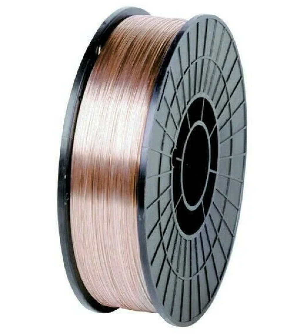
Tag: wire feeding

  • Tweco Liner 42-3035-15, .035-.045, 15′ Conduit 1420-1113 – 1 Piece: Product Breakdown

    Tweco Liner 42-3035-15, .035-.045, 15′ Conduit 1420-1113 – 1 Piece: Product Breakdown

    Product not found.
    “>Tweco Liner 42-3035-15, .035-.045, 15' Conduit 1420-1113 - 1 Piece

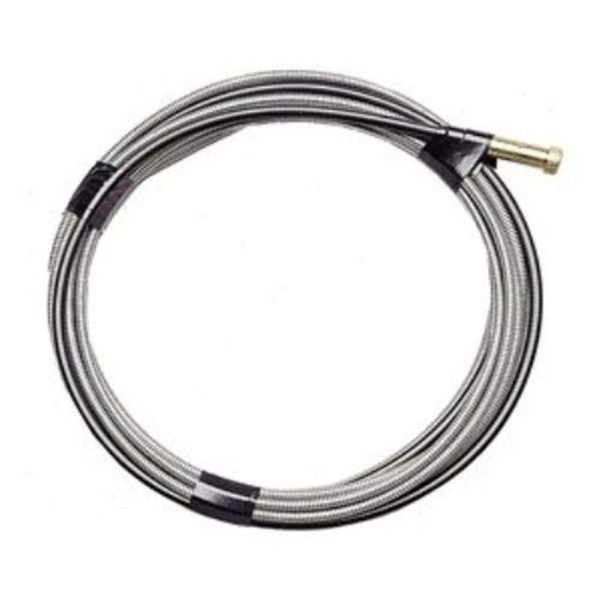
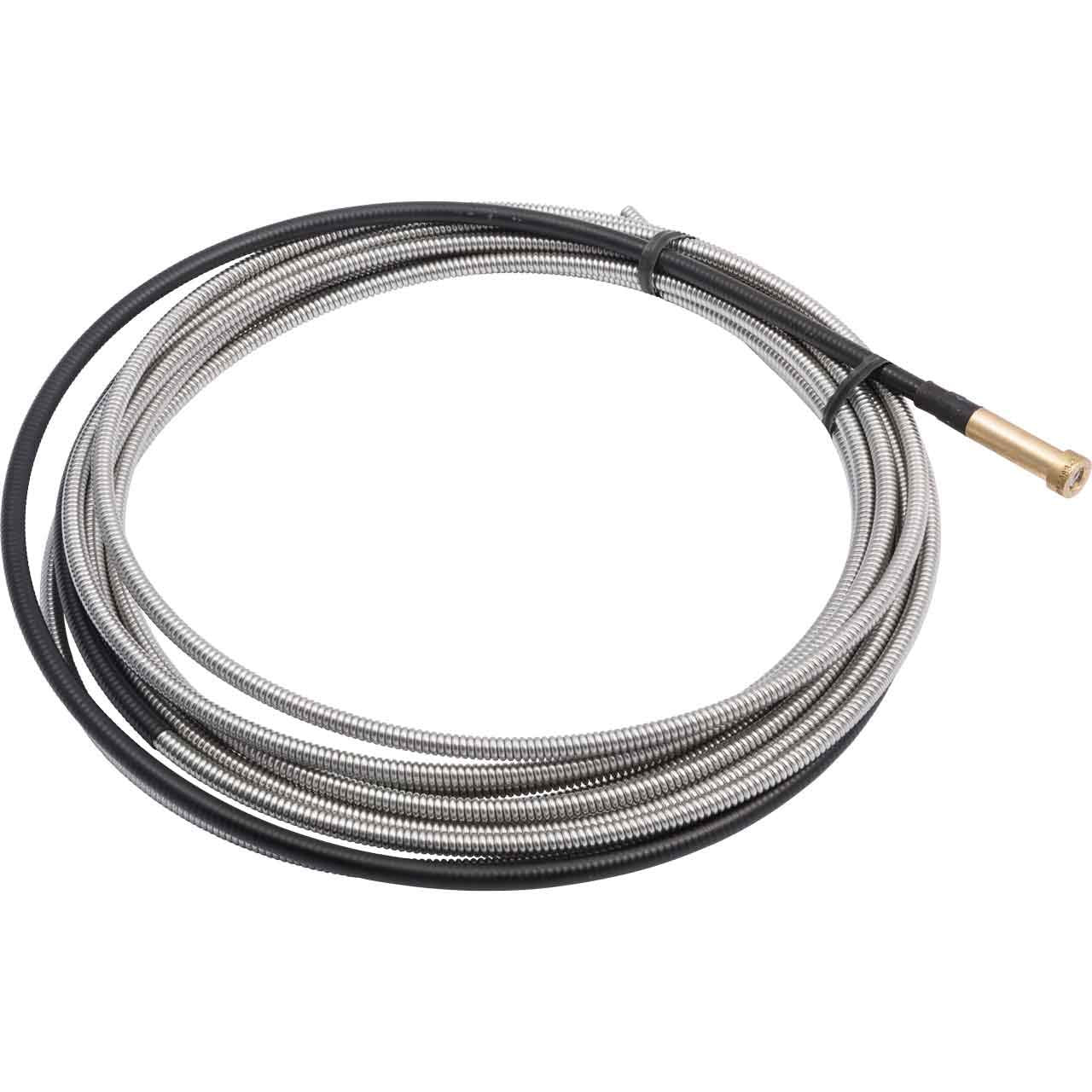
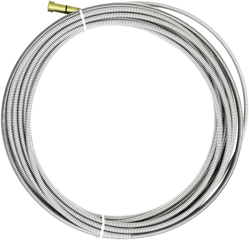
    Wire-feeding problems in MIG welding are often traced back to the liner before operators start changing contact tips, drive rolls, or wire spools. The Tweco Liner 42-3035-15, .035-.045, 15′ Conduit 1420-1113 – 1 Piece is a conduit liner assembly intended for MIG gun wire guidance. Based on the product information provided, it is described as a Tweco Universal Conduit liner that is ready to use out of the box and uses a crimped wire guide that is common to all brands of MIG guns. It is listed for use with Eliminator, Traditional, and Spray Master-style guns.

    This article breaks down what to check before installation, what to verify during a replacement, and how to troubleshoot feeding issues without guessing. If you are buying for maintenance, production support, or shop repair, the goal is simple: confirm fit, confirm wire size, confirm routing, and confirm the liner is the actual problem before you replace parts.

    Key Takeaways

    • The product is a MIG gun conduit liner assembly for wire guidance.
    • It is listed for .035-.045 wire size range.
    • The length is listed as 15′ conduit.
    • The product description says it is ready to use out of the box.
    • Compatibility claims in the source are broad, but final fit should still be verified on the gun model in service.
    • Use it as a replacement part when feeding resistance, birdnesting, or liner wear point to the conduit path.

    What This Part Is For

    A conduit liner supports wire travel from the feeder through the gun cable to the contact tip. When the liner wears, becomes contaminated, or is damaged during installation, the wire can drag, hesitate, or buckle. That can look like a drive roll problem or a spool issue, but the liner is often the first place to inspect.

    The source description identifies this as a universal common crimped wire guide for MIG guns. That does not remove the need to verify gun type, liner path, wire diameter, and overall cable condition. Universal wording should be treated as a starting point, not a final compatibility approval.

    Before You Order or Install

    Check: the gun model currently in service, the wire diameter being run, and the existing liner style. If the machine uses a separate conduit liner system, confirm whether the current setup is designed around this style of replacement.

    Inspect: the drive rolls, inlet guide, torch neck, and contact tip before replacing the liner. A worn liner is only one source of feeding problems. Replacing a liner without checking these other points can leave the root issue unchanged.

    Verify: the cable path is not sharply bent, crushed, or heat damaged. Even a new liner can feed poorly if the cable jacket is damaged or the gun is routed through a tight radius.

    Replacement and Setup Checks

    Check: that the new liner matches the wire size range needed for the job. The provided product title lists .035-.045. If your application is outside that range, do not assume it will feed correctly. Unknown (Verify).

    Inspect: the old liner for copper dust, shavings, flattened sections, rust, or burnback damage. These are common indicators that the liner is no longer providing a smooth wire path.

    Verify: cut length, trim condition, and seating at both ends during installation. A liner that is too long, poorly trimmed, or not seated against the gun components can create drag and inconsistent feed.

    Check: that the wire enters the liner without catching at the feeder end. If the wire wants to buckle at startup, do not force it. Re-check drive roll tension, inlet alignment, and liner entry.

    Troubleshooting Support

    If feeding problems continue after liner replacement, work through the system in order.

    1. Check the wire path.
    Inspect the spool, feeder outlet, inlet guide, liner entry, gun cable, and tip. Any point with obstruction can cause drag.

    2. Inspect drive roll pressure.
    Too much tension can deform the wire and create feeding issues. Too little tension can cause slipping. Adjust only after confirming the liner path is clear.

    3. Verify the contact tip condition.
    A worn or overheated tip can mimic liner problems. If the wire feeds freely through the liner but hangs at the end, the tip may be part of the restriction.

    4. Check for contamination.
    Dirt, metal dust, and fragments from wire can collect in the liner. If the liner was exposed during maintenance, verify that no debris entered the conduit during installation.

    5. Inspect the gun cable routing.
    If the cable is bent too tightly, feeding will suffer even with a new liner. Verify that the gun can move through its normal work envelope without binding.

    Product and Parts Notes

    The provided product information says the liner is ready to use right out of the box and is packaged as one piece. The source also describes it as a Tweco Universal Conduit liner. Those are the only packaging and use details that should be relied on here. No additional dimensions, certifications, materials, or cross-brand approvals are confirmed in the provided source, so those details remain Unknown (Verify).

    If you are selecting this part for a maintenance shelf, the practical buying question is whether your shop replaces the entire liner assembly at once or trims and fits liners in-house. The source indicates a ready-to-use item, which supports field replacement, but installation practice still depends on the gun setup and shop procedure.

    Safety Notes

    • Lock out and isolate the welding system before servicing the gun or feeder.
    • Do not service a hot gun, neck, or contact tip assembly.
    • Use cut-resistant gloves when handling trimmed liner ends and wire.
    • Verify that the wire spool is secured before removing or installing liner components.
    • Do not force wire through a damaged cable or kinked conduit.

    Related Selection Starting Point

    If your maintenance task also includes filler metal review, use the internal WSP content below as a selection starting point only. It is not a procedure approval and does not replace WPS review or job-specific qualification requirements.

    FAQ

    Is the Tweco Liner 42-3035-15 a universal liner?
    The provided product description says it is a Tweco Universal Conduit liner and references broad MIG gun style compatibility. Final fit still needs to be verified on the actual gun and feeder setup in service.

    What wire size is this liner intended for?
    The product title lists .035-.045. If your wire is outside that range, compatibility is Unknown (Verify).

    What should I inspect before blaming the liner for feed issues?
    Check the drive rolls, inlet guide, contact tip, cable routing, and wire spool condition first. A feeding problem can come from any point in the wire path.

    Does the source confirm all dimensions and certifications?
    No. Only the listed product title and description were provided. Any unlisted technical detail is Unknown (Verify).

    Sources Checked

    • ArcWeld product page: Tweco Liner 42-3035-15, .035-.045, 15′ Conduit 1420-1113 – 1 Piece
    • Provided internal product short description for the same item
    • Provided internal link: Aluminum ER 5554 3/64″ X 5lb. MIG Welding Wire Spool By Washington Alloy – Weld Support Parts Blog

    Related Arc Weld Part

    Tweco Liner 42-3035-15, .035-.045, 15' Conduit 1420-1113 - 1 Piece

    Tweco Liner 42-3035-15, .035-.045, 15' Conduit 1420-1113 – 1 Piece

    Each conduit liner wire has a crimped wire guide that is universal common to all brands of MIG guns. For all guns (Eliminator, Traditional and Spray Masterâ„ styles). Tweco Universal Conduit liner is ready to use right out of the box. Package of (1)

    View at Arc Weld Store

    Related Weld Support Guides

  • Washington Alloy 2 Lb. Spool Mig Welding Wire 308L Stainless Steel (.030 X 2lb.): Replacement Part Breakdown

    No products found.

    Washington Alloy 2 Lb. Spool Mig Welding Wire 308L Stainless Steel (.030 X 2lb.) is a stainless MIG wire entry that buyers often evaluate as a replacement consumable for light-duty stainless work. For maintenance buyers and welding support teams, the main job is not just identifying the wire by name. It is confirming whether the wire diameter, stainless grade, spool size, and feeder setup match the application before the job starts.

    This breakdown focuses on practical checks. It does not assume machine settings, base metal compatibility, or certification status beyond what is provided in the product title and ASIN registry reference. Where details are not confirmed, they are marked Unknown (Verify).

    Key Takeaways

    • This is a stainless MIG welding wire identified as 308L in .030 in. diameter and 2 lb. spool form.
    • The ASIN provided is B081X76HSY. Use the allowed product listing reference for purchase verification.
    • Compatibility depends on feeder drive setup, liner condition, contact tip size, shielding gas, and job requirements. Verify all of these before loading wire.
    • Do not assume the wire is correct for all stainless grades or all transfer modes. Verify the base metal and procedure first.

    Product and Parts Breakdown

    The product name indicates three important points: wire type, wire size, and spool weight. That is the first level of verification for a replacement consumable.

    • Wire type: Stainless steel MIG wire, 308L designation.
    • Wire diameter: .030 in. This is commonly written as 0.030 in. Verify the machine’s drive rolls and contact tip size before use.
    • Spool weight: 2 lb. Verify whether your wire feeder accepts this spool format without adapters or additional spindle hardware.
    • Brand/product family: Washington Alloy, per the provided product name.
    • ASIN: B081X76HSY.

    If your maintenance team is replacing a depleted wire package, check the feeder path first. A stainless wire can feed poorly if the liner is worn, the tip is undersized, or the drive roll tension is too high. A bad feed path often gets mistaken for a bad spool.

    Inspect: drive rolls, inlet guide, liner, gun cable routing, and contact tip condition. Verify: the wire path is clean and sized for .030 in. wire before loading the new spool.

    Fitment and Use Checks

    For buyers, the important question is not only “is it stainless wire?” but “will it feed and perform in this setup?” Start with the machine configuration and work outward.

    1. Check wire diameter. Confirm the machine is set up for .030 in. wire. If the feeder is currently configured for .035 in. or another size, change the tip, drive roll groove, and related hardware as required.
    2. Inspect drive rolls. Stainless wire usually needs consistent feed pressure without deformation. Too much tension can flatten the wire and increase birdnest risk.
    3. Verify liner condition. A contaminated or worn liner can create unstable feed and arc variation. Replace or clean only according to the equipment manual.
    4. Check spool fit. The spool is 2 lb. Verify spindle size, brake drag, and hub retention. Unknown (Verify): whether your specific feeder needs an adapter.
    5. Confirm shielding gas. The correct gas mix depends on the procedure and base metal. Unknown (Verify): gas specification for this exact application.

    When a stainless wire does not run correctly, do not jump to voltage changes first. Inspect the feed path, then the contact tip, then the liner. Most early feed complaints are mechanical, not electrical.

    Troubleshooting and Support

    Use this sequence when a new spool does not perform as expected.

    Issue: Wire hesitates or feeds inconsistently

    • Check: spool rotation on the spindle.
    • Inspect: drive roll slip, liner blockage, and gun cable kinks.
    • Verify: the contact tip is .030 in. and not worn oversize.

    If the spool over-runs when feeding stops, reduce brake drag carefully. If the wire birdnests, reduce drive pressure and confirm the liner path is smooth.

    Issue: Arc is unstable or harsh

    • Check: polarity and machine setup against the procedure.
    • Inspect: tip wear, stickout consistency, and gun consumable cleanliness.
    • Verify: the wire surface is clean and dry before loading.

    Stainless wire can show problems quickly if contamination is present. Keep the spool sealed until needed and do not handle the wire with oily gloves.

    Issue: Excess spatter or poor bead appearance

    • Check: shielding gas flow and nozzle condition.
    • Inspect: nozzle buildup, tip spatter, and workpiece contamination.
    • Verify: base metal preparation is adequate for stainless work.

    For surface prep guidance, see the related article on Stainless Steel Wire Wheel Brush for Welding Surface Prep: 8mm Rotary Drill Attachment.

    Related Stainless Wire Guidance

    If your team is comparing stainless wire options, review the article on Best MIG Wire for Stainless Steel (ER308L vs ER309L). It helps separate selection logic from brand preference. That matters when the replacement part must match the job, not just the box label.

    For broader stainless process planning, the article on Best Flux Core Wire for Stainless Steel Welding can help clarify when flux-core and solid wire are being confused in procurement.

    For a different Washington Alloy spool format, see Aluminum ER 5554 3/64” X 5lb. MIG Welding Wire Spool By Washington Alloy. It is not the same product, but it is useful as a comparison point for spool size and inventory handling.

    Safety Notes

    • Wear eye protection when loading wire and trimming the leader end.
    • Keep hands clear of the drive rolls and wire path during feed tests.
    • Do not use damaged spools, crushed packaging, or visibly contaminated wire.
    • Follow the welding procedure, machine manual, and site safety rules for stainless welding.
    • Unknown (Verify): exact consumable disposal and storage requirements for your facility.

    FAQ

    Is this wire confirmed for every stainless job?

    No. The product title identifies 308L stainless MIG wire, but job compatibility still depends on the base metal, procedure, shielding gas, and machine setup. Verify before use.

    Will .030 in. wire feed through any MIG gun?

    No. The gun must be set up for .030 in. wire with the correct contact tip, liner condition, and drive roll groove. Verify the feeder hardware first.

    Can a 2 lb. spool fit any wire feeder?

    Not automatically. Spindle and hub fit vary by feeder design. Unknown (Verify): adapter requirement for your machine.

    What is the best way to avoid feeding problems?

    Inspect the liner, drive rolls, contact tip, and spool brake before welding. Clean feed paths and correct sizing prevent most issues.

    Sources Checked

    • Provided product reference: Washington Alloy 2 Lb. Spool Mig Welding Wire 308L Stainless Steel (.030 X 2lb.)
    • Provided ASIN registry reference: B081X76HSY
    • Allowed internal links on stainless wire selection, surface prep, and related Washington Alloy spool content

    For purchase verification, use the allowed product reference associated with ASIN B081X76HSY. Do not assume fit or procedure settings until the feeder, consumables, and job specification are verified.

    Matched Replacement Option

    No products found.

    Disclosure: As an Amazon Associate, Weld Support Parts may earn from qualifying purchases.

    Related Weld Support Guides

  • MIG Gun Liner Compatibility Guide

    Product not found.
    “>Lincoln Electric K2951-1 Magnum PRO Curve 300 MIG Welding Gun, Semi-Automatic, 10 ft Cable

    Replacement MIG gun liners look simple, but the wrong liner will cause feed drag, birdnesting, inconsistent arc start, and burnback. MIG liner compatibility depends on the gun model, feeder-to-gun connection, wire diameter, liner type, and the required liner length.

    Key Takeaways

    • Match the liner to the gun and feeder configuration, not just the wire diameter.
    • Verify liner type: steel, graphite, or other liner material. Unknown (Verify) if the gun manual does not specify.
    • Measure the required liner length from feeder connection to gun neck or tip path per the gun instructions.
    • Trim only as directed by the gun or liner manufacturer. Over-trimming can create feeding problems.
    • If wire feeding becomes erratic after a liner change, check for kinks, wrong diameter, poor cutoff, and incorrect installation before replacing the gun.

    What MIG Liner Compatibility Actually Means

    A compatible MIG liner must fit the gun physically and support the wire size you are running. A liner that is correct for .030 in. wire may not feed .035 in. wire properly, especially on longer gun leads or with softer wire. Compatibility also depends on the gun connection style, the neck style, and whether the liner is intended for steel, aluminum, or flux-cored applications.

    If any of those points are unknown, verify them before ordering. Do not assume all liners in the same brand family are interchangeable.

    What to Verify Before Ordering a Replacement Liner

    • Gun model: Check the exact MIG gun model number.
    • Feeder and connection style: Verify the rear connection at the feeder and the front connection at the neck. Unknown (Verify) if not documented.
    • Wire diameter: Confirm the wire size in use, such as .030, .035, or .045 in.
    • Wire type: Solid wire, flux-cored wire, or aluminum wire may require different liner behavior.
    • Liner length: Match the required length to the cable and gun setup.
    • End fittings: Some liners need specific end fittings or cut lengths. Unknown (Verify) if not specified.

    How Wire Diameter Affects Liner Choice

    The liner must support the wire diameter without excess friction or excessive clearance. Too tight, and the wire drags. Too loose, and the wire can wander, snag, or feed inconsistently. That matters more as gun length increases.

    General rule: use the liner size specified for the wire you are running. If the feeder is set up for one size and the liner is sized for another, verify the whole feed path before operating.

    How Liner Length Affects Feed Quality

    A liner that is too short will not support the wire path correctly. A liner that is too long can buckle, bind, or prevent proper seating at the feeder or gun neck. Cut length matters. Measure and trim only to the instructions for that liner and gun.

    Do not guess the cutoff point. Small errors can create intermittent feed issues that look like a bad drive roll or bad gun when the liner is the actual problem.

    Installation Steps

    1. Turn off the power source and isolate the feeder before service.
    2. Remove the contact tip and nozzle.
    3. Back off drive roll pressure and remove the wire if needed.
    4. Remove the old liner and inspect the gun cable for kinks, crushed sections, or liner debris.
    5. Insert the new liner from the correct end.
    6. Seat the liner fully at the feeder end and at the gun neck end per the gun instructions.
    7. Trim only to the specified length. Unknown (Verify) if the gun manual does not show the cutoff method.
    8. Reinstall consumables and rethread wire.
    9. Set drive pressure and test wire feed at low speed first.

    Troubleshooting Poor Wire Feeding

    Symptom: Wire surges or hesitates

    • Check for incorrect liner size.
    • Inspect for liner kinks or crushed cable sections.
    • Confirm the liner is fully seated at both ends.
    • Verify drive roll tension is not too loose or too tight.

    Symptom: Wire birdnests at the feeder

    • Check for excessive drag in the liner.
    • Confirm the liner is not blocked by debris, rust, or wire shavings.
    • Verify the tip is not restricted.
    • Inspect drive rolls for wear or mismatched groove type.

    Symptom: Burnback or poor arc starts

    • Check whether the liner is cut too short or not seated properly.
    • Verify the contact tip size matches the wire.
    • Confirm the wire path is smooth from feeder to tip.

    Symptom: Feed is worse after liner replacement

    • Confirm the replacement liner matches the gun model and wire diameter.
    • Check whether the liner was trimmed to the wrong length.
    • Look for a damaged cable or incorrect installation at the feeder or neck.

    When to Replace the Liner

    Replace the liner when wire feeding becomes inconsistent and cleaning does not restore performance. Common indicators include visible contamination, rust-colored dust, heavy wire shavings, intermittent drag, or a liner that has been kinked or overheated. If the gun has been used with spatter backflow or contaminated wire, inspect the whole feed path, not just the liner.

    Product and Parts Note

    For users cross-checking a replacement gun configuration, the following product is provided in the catalog for reference only:

    Lincoln Electric K2951-1 Magnum PRO Curve 300 MIG Welding Gun, Semi-Automatic, 10 ft Cable

    Lincoln Electric K2951-1 Magnum PRO Curve 300 MIG Welding Gun, Semi-Automatic, 10 ft Cable

    Lincoln Electric K2951-1 Magnum PRO Curve 300 MIG welding gun is built for semi-automatic MIG welding applications and includes a 10 ft cable for controlled handling and day-to-day shop use; the Curve 300 design is intended to support consistent feeding and operator comfort for fabrication and maintenance work—please confirm your welder/feeder and gun connection style match the Magnum PRO Curve 300 configuration b…

    View at Arc Weld Store

    Confirm the feeder connection style, gun model, and liner requirement before ordering any replacement part.

    Safety Notes

    • Lock out and isolate the welding power source before service.
    • Wear gloves when handling cut liner ends. They can be sharp.
    • Do not run wire feed tests with the nozzle removed near energized equipment without proper precautions.
    • Replace damaged cables, liners, and consumables before returning the gun to service.

    FAQ

    Can I use any liner with the same wire diameter?

    No. Wire diameter is only one part of compatibility. You must also verify gun model, feeder connection, liner type, and length.

    Why does my new liner feed worse than the old one?

    Common causes are wrong size, incorrect trim length, poor seating, cable damage, or drive roll setup issues.

    Do I need a special liner for aluminum wire?

    Often yes, but the exact requirement depends on the gun and feeder system. Unknown (Verify) unless the manufacturer states the liner type.

    How do I know if the liner is too long?

    Signs include binding, poor seating, and unstable feed after installation. Follow the gun instructions for the exact cutoff method.

    Sources Checked

    • Weld Support Parts blog: Welding Cable Connector Compatibility Guide (Dinse, Tweco, Cam-Lok & Stud Types)
    • Weld Support Parts blog: Welding Electrode Holder: Stinger Guide & Stick Welding Tips
    • Weld Support Parts blog: ArcOne S240-10 Auto-Darkening Welding Filter: Shade 10 Lens Support Guide
    • Weld Support Parts blog: Aluminum ER 5554 3/64″ X 5lb. MIG Welding Wire Spool By Washington Alloy

    Related Weld Support Guides

  • MIG Gun Liner Feeding Problems: Troubleshooting Birdnesting, Burnback, and Wire Drag

    MIG Gun Liner Feeding Problems: Troubleshooting Birdnesting, Burnback, and Wire Drag

    A worn, kinked, contaminated, or wrong-size MIG gun liner is one of the most common causes of birdnesting, burnback, erratic arc starts, wire chatter, and poor feed stability. Before replacing the feeder motor, gun, contact tip, or drive rolls, verify the wire diameter, liner size, gun length, drive-roll style, tip condition, and cable routing. A liner that is too tight, too dirty, cut too short, or crushed near the power pin can create enough drag to make the feeder slip or shove wire into the drive-roll compartment.

    Common Symptoms

    • Wire birdnests at the feeder or piles up near the drive rolls.
    • Arc starts, then burns back into the contact tip.
    • Wire feeds with a pulsing, jerky, or scratching feel.
    • Drive rolls slip even after tension adjustment.
    • Contact tips wear quickly or seize to the wire.
    • Weld bead becomes inconsistent even with correct voltage and wire feed speed.

    Likely Causes

    SymptomLikely liner-related causeWhat to check first
    BirdnestingExcess drag or wrong liner IDWire diameter, liner marking, cable bends
    BurnbackWire slows before exiting tipTip bore, liner contamination, stickout
    Wire chatterKinked liner or crushed gun cableGun laid straight during test feed
    Drive-roll slippingRestriction downstream of rollsNozzle, tip, diffuser, liner, power pin
    Aluminum feed troubleWrong liner material or excessive push distanceU-groove rolls, liner type, gun length

    Inspection Steps

    1. Remove the contact tip and feed wire through the gun. If feed improves immediately, inspect the tip size and wear.
    2. Lay the gun cable as straight as practical. If feeding improves, the liner may be worn, kinked, or too tight for the wire.
    3. Back off drive-roll tension, then reset it only high enough to feed without slipping. Too much tension can deform wire and worsen liner drag.
    4. Remove the liner and inspect both ends for burrs, copper dust, rust flakes, wire shavings, or burn marks.
    5. Check that the liner is trimmed to the gun manufacturer’s required length. A short liner can leave a gap at the power pin or diffuser.
    6. Confirm the liner supports the installed wire diameter and wire type.

    Compatibility Notes

    Liners are not universal just because the wire diameter looks similar. Verify the gun model, backend connector, consumable series, liner retaining system, wire diameter range, and whether the wire is steel, stainless, flux-cored, or aluminum. Flux-cored wire often needs a liner and drive-roll setup that handles a softer tubular wire without crushing it. Aluminum usually requires low-friction liner materials, correct drive rolls, and short, straight feed paths unless a spool gun or push-pull gun is being used.

    Test Procedures

    • Tip-off feed test: Remove the contact tip and feed wire. If drag drops, replace the tip or verify tip size.
    • Gun-straight test: Feed wire with the gun cable straight. If the problem disappears, suspect liner wear or cable restriction.
    • Hand-pull test: With the drive rolls open, pull wire through the gun by hand. Heavy resistance points to liner, tip, diffuser, or cable damage.
    • Short-feed test: Remove the gun from the feeder and feed wire at the drive rolls only. If the feeder runs smoothly without the gun, troubleshoot the gun assembly before replacing feeder parts.

    Field Fix vs Proper Fix

    A temporary field fix is to straighten the gun cable, replace the contact tip, reduce sharp bends, blow clean dry air through the liner, and reset drive-roll tension. This may get a job through a shift, but it does not correct a worn, undersized, kinked, or contaminated liner. The proper repair is to install the correct liner for the gun and wire, trim it correctly, replace worn tips and diffusers, and verify drive-roll type and tension.

    Visual Wear Indicators

    • Rust, copper dust, or black residue coming out of the liner.
    • Flattened or crushed wire after the drive rolls.
    • Deep grooves in the contact tip bore.
    • Burn marks or melting near the liner end.
    • Liner end cut at an angle, mushroomed, or missing its retaining cap.
    • Gun cable jacket kinked, pinched, or heat damaged.

    What To Verify Before Ordering

    • Gun brand and exact gun model.
    • Backend connector style, such as Miller, Lincoln, Tweco, Euro, or other machine-specific connection.
    • Wire diameter currently used and any planned wire changes.
    • Wire type: solid steel, stainless, aluminum, metal-cored, self-shielded flux-cored, or gas-shielded flux-cored.
    • Gun length and amperage rating.
    • Consumable family and contact tip series.
    • Whether the liner is conventional, front-loading, jump liner, conduit, or push-pull compatible.

    Common Wrong-Part Mistakes

    • Ordering by wire size only instead of gun model and liner system.
    • Installing a steel liner for aluminum wire.
    • Using a contact tip smaller than the actual wire diameter.
    • Cutting the liner too short and leaving an unsupported gap.
    • Reusing worn drive rolls after installing a new liner.
    • Increasing drive-roll tension to overcome a blocked liner.

    Related Failure Paths

    Liner restriction can look like a feeder problem, but it can also be tied to contact tip burnback, incorrect drive rolls, wrong shielding gas setup, poor work-lead connection, damaged diffuser threads, or overheated gun components. When the liner is replaced, inspect the whole feed path from spool hub to contact tip instead of treating the liner as an isolated part.

    Safety Notes

    • Turn off and disconnect welding output before disassembling the gun or feeder.
    • Wear eye protection when feeding wire with the gun pointed away from personnel.
    • Do not use oxygen to blow out a liner.
    • Keep hands clear of drive rolls during feed tests.
    • Replace heat-damaged gun parts instead of forcing them back into service.

    Sources Checked

    Parts and compatibility should be confirmed against the exact MIG gun parts breakdown, OEM consumables guide, and machine manual before ordering. When the welder brand requires code-number lookup, verify the code number from the machine nameplate rather than relying only on a product number.

  • Why does my MIG wire keep birdnesting? (Fast fix in 10 minutes)

    You pull the trigger, the drive rolls spin, and suddenly you’ve got a tangled mess behind the rollers. That’s birdnesting. This guide gives you a fast diagnosis and a clean troubleshooting flow that fixes it without over-adjusting your machine.

    Where to Buy (Quick Fix Parts)

    Most birdnesting comes from wire drag (liner/tip) or wire being crushed (drive roll tension/incorrect rolls). Start with the parts that fail most often.

    Top Pick (Primary Fix)

    If the wire is hanging up, a fresh liner is the quickest “real fix” on a worn gun.

    Disclosure: As an Amazon Associate, I earn from qualifying purchases.

    Backup / Consumable Option

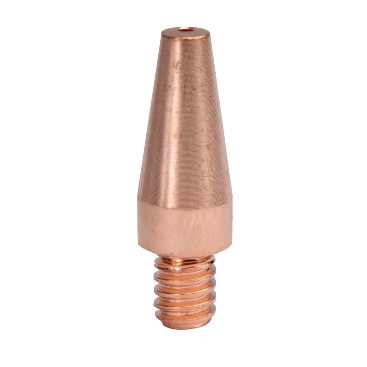
    If the wire is sticking at the end of the gun, a new contact tip is the fastest low-cost test.

    Key Takeaways

    • Birdnesting is usually wire drag (liner/tip) or too much drive roll tension.
    • If it’s not fixed in 2–3 minutes, replace the consumable instead of chasing settings.
    • Keep the gun lead as straight as possible while testing—tight coils create false problems.
    • Verify you’re using the correct drive rolls for the wire type (solid vs flux-core).

    Symptoms (Fast Diagnosis)

    • Wire piles up behind the drive rolls (classic “nest”)
    • Drive rolls slip, chatter, or grind a flat spot into the wire
    • Wire feeds fine with the gun straight, but birdnests when you bend the lead
    • Wire stubs into the puddle, arc gets erratic, then the feeder jams
    • You see copper shavings or heavy dust near the drive rolls (wire being crushed)

    Root Causes (Mapped to Symptoms)

    • Birdnest happens immediately when you pull the trigger
      • Likely cause: wire is blocked at the contact tip (spatter, wrong size tip, worn tip) or liner is plugged/kinked
    • Birdnest happens when the gun lead is bent or coiled
      • Likely cause: liner friction (dirty/worn liner, wrong liner size, kinked lead)
    • Wire has deep grooves / flattened sides
      • Likely cause: drive roll tension too tight or wrong drive roll style (knurled vs V-groove mismatch)
    • Drive rolls spin but wire doesn’t move
      • Likely cause: tension too loose or wire is stuck at the front end (tip/liner), causing slip
    • Inconsistent feed + popping arc before the nest
      • Likely cause: drag at tip/liner, plus poor wire path (spool drag, sharp inlet guide angle)

    Quick Fix (Do This First)

    Replace the common failure parts first. Don’t start by cranking tension or changing voltage.

    1. Install a new contact tip (correct size for your wire).
    2. Blow out or replace the liner if the lead is old, kinked, or contaminated.
    3. Set drive roll tension using the “gloved pinch test”: with welding gloves on, pinch the wire as it exits the gun and pull the trigger.
      • If the rolls instantly birdnest: tension is too tight or the wire is blocked at the tip/liner.
      • If the rolls slip smoothly: tension is closer to correct.

    Safety note: Wear safety glasses that meet ANSI Z87.1 when clipping wire, blowing out liners, or handling wire ends. Gloves recommended. Ensure adequate ventilation when welding.

    Step-by-Step Fix

    Follow this in order. Change one variable at a time.

    1. Stop and cut the wire clean
      • Cut off the kinked section. A bent wire end will snag the liner/tip.
    2. Check the contact tip first (fastest test)
      • Remove the tip and try feeding wire through the gun.
      • If it feeds better with the tip removed, your tip is worn, clogged, or mismatched.
    3. Straighten the gun lead
      • Lay the lead straight on the floor/bench and test feed again.
      • If it only fails when bent, suspect liner friction or a kinked lead.
    4. Inspect drive rolls and wire path
      • Confirm roll type matches wire:
        • Solid wire typically uses V-groove rolls.
        • Flux-core often uses knurled rolls (verify your machine’s recommendation).
      • Make sure the wire is centered through the inlet guide and into the liner.
    5. Set spool tension (don’t overtighten)
      • Too much spool drag increases load and encourages slipping/crushing.
    6. Set drive roll tension last
      • Increase only until the wire feeds reliably without crushing.

    Parts That Actually Fix This

    • Liner
      • Replace when: feed worsens with bends, liner is old/dirty, you see rust/dust, or the lead has been kinked.
      • Adjust when: lead routing is the issue (tight loops, sharp bends).
    • Contact tips
      • Replace when: wire sticks, arc is unstable, tip is visibly worn/oval, or spatter blocks the bore.
      • Adjust when: you’re running the wrong size tip for the wire (verify).
    • Drive rolls
      • Replace when: grooves are worn smooth, wire slips constantly, or rolls are the wrong profile for the wire.
      • Adjust when: tension is simply mis-set.
    • Diffuser / nozzle
      • Replace when: spatter buildup interferes with tip seating or you can’t keep the tip tight/centered.

    Replace vs Adjust (Fast Decision Table)

    ProblemAdjust FirstReplace
    Birdnest happens only when lead is bentStraighten lead / reroute cableLiner (if still drags)
    Wire is flattened or shaved by rollsReduce drive roll tensionDrive rolls (if worn/wrong type)
    Wire sticks or feeds better with tip removedConfirm tip size / clean spatterContact tip

    Rule: If it’s not fixed in 2–3 minutes, replace the consumable.

    Prevention Tips

    • Keep the gun lead as straight as practical; avoid tight coils on the floor.
    • Clip wire clean every time you change spools; don’t feed a kinked end into the liner.
    • Store wire dry; rust and dust increase liner friction.
    • Routine intervals (general guidance): replace tips when feed/arc becomes inconsistent; replace liners when feed becomes bend-sensitive or contamination is visible. Exact intervals are Unknown (depends on usage and environment).

    FAQ

    Why does my MIG wire birdnest when I increase wire speed?

    Higher wire speed increases push force. If there’s any restriction (tip/liner drag) or tension is too tight, the rolls will overpower the wire path and it will pile up.

    Can a bad contact tip cause birdnesting?

    Yes. A worn, spattered, or mismatched tip can grab the wire. A quick test is feeding with the tip removed (power off, safe handling).

    Should I tighten the drive rolls to stop birdnesting?

    Not as a first move. Too much tension crushes the wire, increases drag, and can make birdnesting worse. Replace/verify the tip and liner first.

    Why does it birdnest with flux-core more often?

    Flux-core wire can be softer and more sensitive to crushing, and it’s often run through knurled rolls. Wrong roll type or too much tension is a common cause (verify your machine’s recommendation).

    Internal Links

    • For a broader workflow, see our complete MIG wire feed troubleshooting guide.
    • If your wire is sticking to the tip instead of nesting, use this burnback troubleshooting guide.
    • If you’re getting tangles at the feeder, this breakdown of birdnesting causes and fixes helps you isolate the exact failure point.
  • Try Amazon Prime Free