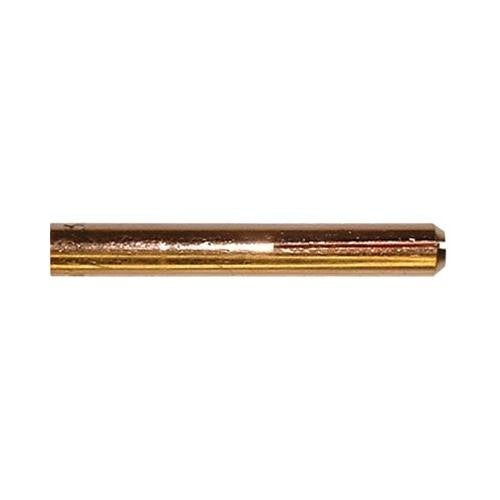
Tag: TIG welding

  • ERCuSi-A TIG / GTAW Filler Metal: Selection and Compatibility Checks

    ERCuSi-A TIG / GTAW Filler Metal: Selection and Compatibility Checks

    ERCuSi-A TIG / GTAW Filler Metal

    ERCuSi-A TIG / GTAW filler metal is a common starting point for silicon bronze braze-welding and certain copper-alloy applications. It is often selected when the job calls for lower base-metal dilution, improved cosmetic appearance, or joining sheet metal with controlled heat input. That said, the filler metal name alone does not make it a qualified choice. The weld support team still needs to verify the WPS, the base metal, the service environment, and the manufacturer data sheet before the first arc starts.

    This guide is for selection checks, not procedure approval. If the material, joint design, or service condition is uncertain, stop and verify before welding.

    Key Takeaways

    • ERCuSi-A is a starting point for silicon bronze TIG/GTAW work, not a blanket approval for every copper or sheet metal job.
    • Check the WPS first. If no WPS exists, verify whether the job requires one and whether ERCuSi-A is permitted.
    • Confirm base metal grade, thickness, and service conditions before selecting wire size or travel plan.
    • Use the filler metal finder and manufacturer data sheet to confirm the intended use, not just the classification name.
    • For uncertain compatibility, mark the detail as Unknown (Verify) and route it for review.

    Where ERCuSi-A Fits

    ERCuSi-A is typically associated with silicon bronze filler selection for TIG/GTAW. In support work, it is often evaluated for braze-welding, sheet metal repair, cosmetic build-up, and compatible copper-alloy work. The practical benefit is usually lower heat input than a fusion weld on thin or sensitive base metal. That does not mean it is suitable for every repair. Joint design, fit-up, corrosion exposure, fatigue loading, and post-weld requirements can change the decision.

    If the base metal is not clearly identified, treat it as Unknown (Verify). Do not assume a bronze filler is acceptable just because the material looks similar to copper or brass.

    Check the WPS Before You Select Wire

    Start with the welding procedure specification if one exists. The WPS should define whether the job allows braze-welding, which filler metal classifications are approved, and whether any preheat, shielding gas, or joint limits apply. If the WPS is missing, incomplete, or outdated, stop and verify before ordering wire or setting up the torch.

    Check:

    • WPS number, revision, and job scope
    • Approved filler metal classification
    • Base metal group and thickness range
    • Required shielding gas and process limits
    • Any code or customer restrictions

    Inspect: the joint area for contamination, paint, plating, oxide buildup, oil, and moisture. Silicon bronze work is sensitive to surface condition. Dirty edges can give poor wetting, unstable arc behavior, or weak cosmetic results.

    Verify: whether the repair is structural, cosmetic, or service-critical. If the repair carries load, pressure, or corrosion exposure, the filler choice may require formal approval. Unknown (Verify) is the correct status until that review is complete.

    Base Metal Compatibility Checks

    ERCuSi-A is not a universal match for all copper alloys or all mixed-metal joints. The support team should confirm the actual base metal grade before proceeding. That includes checking whether the part is copper, brass, bronze, or a coated steel assembly. If the part was previously repaired, identify the existing filler if possible. Mixed chemistry can change wetting behavior and service performance.

    Check:

    • Base metal identification from print, mill cert, tag, or site record
    • Thickness and heat sensitivity
    • Whether dissimilar metal joining is involved
    • Whether the application is decorative, low-load, or service-critical

    Inspect: edges and joint fit-up. Large gaps may push the repair outside the intended use of the filler. If fit-up is inconsistent, verify whether build-up or backing is needed, or whether the repair should be reworked before welding.

    Verify: the service temperature, corrosion exposure, and any downstream finishing steps. A filler that wets well during welding may still be the wrong choice if the assembly sees chemicals, high wear, or code-controlled service.

    Filler Metal Finder as a Selection Starting Point

    Use the WSP filler metal finder as a selection starting point only. It can help narrow the search by process, classification, or base-material family, but it does not replace the WPS or manufacturer data sheet. If the finder suggests ERCuSi-A for the job, treat that as a lead to review, not a final approval.

    When comparing options, confirm whether the application needs silicon bronze, a different copper-alloy filler, or another repair method entirely. If the part is aluminum, steel, stainless, cast iron, or an unknown alloy, do not assume ERCuSi-A is appropriate. Mark the fit as Unknown (Verify) until the compatibility question is resolved.

    Practical Setup and Handling Checks

    Before welding, check the wire condition and setup. Filler rod should be clean, dry, and free of heavy oxidation or contamination. Keep rods separated from steel grinding dust, oil, and shop debris. Use the size called out by the WPS or job plan. If the wire diameter is not specified, verify the required size before selecting from stock.

    Check: torch setup, cup size, tungsten condition, and shielding gas flow. For general TIG setup support, see the Square Wave 205 TIG Cup Size Selection Guide for cup size, gas lens, and stickout checks. Although that article is not specific to ERCuSi-A, the setup discipline is the same: stable shielding, clean arc starts, and correct torch geometry.

    Inspect: tungsten for contamination or improper grind. If the arc wanders, starts dirty, or black specks appear, review the tungsten and gas path before blaming the filler. See the TIG Tungsten Contamination Troubleshooting guide for re-grind and contamination checks.

    Verify: arc stability, wetting behavior, and bead shape on a test coupon when the application is new, thin-gauge, or service-critical.

    Troubleshooting Support Checks

    If the bead is rough, the wetting is poor, or the repair lifts at the edges, work through the basic checks in order:

    • Check joint cleanliness again.
    • Inspect shielding gas coverage and torch angle.
    • Verify travel speed and heat input.
    • Confirm that the base metal and filler are actually compatible.
    • Review whether the job should be braze-welded or repaired by another method.

    For arc wander or unstable starts, grounding and torch setup can also matter. The TIG arc wandering causes guide covers tungsten, gas, ground, and AC setup checks that apply broadly to GTAW troubleshooting.

    Safety Notes

    Follow standard welding safety practices. Use eye and face protection, gloves, and flame-resistant clothing. Provide ventilation appropriate for the work area. Clean coatings, oils, and plated surfaces before welding only if the site procedure allows it. If there is any chance of unknown coating chemistry, treat the job as a fume risk and verify controls before proceeding.

    Do not weld on pressure-containing, load-bearing, or regulated parts without confirming the required procedure and approval path. If the job classification is uncertain, stop and verify with the supervisor, engineer, or quality contact.

    FAQ

    Q: Is ERCuSi-A the right choice for every copper repair?
    A: No. It is a starting point for silicon bronze TIG/GTAW selection. Confirm the exact base metal, joint design, and service condition first.

    Q: Can I use ERCuSi-A just because the finder suggests it?
    A: No. The filler metal finder is a selection aid, not procedure approval. The WPS and manufacturer data sheet still control the final choice.

    Q: What should I do if the base metal is not clearly identified?
    A: Treat it as Unknown (Verify). Do not assume compatibility from appearance alone.

    Q: Does ERCuSi-A automatically fit structural or code work?
    A: Not automatically. Verify code requirements, WPS limits, and customer approval before using it on regulated work.

    Sources Checked

    Notes: AWS spec listed on the source page: AWS A5.7. Any additional technical detail not confirmed on the provided source pages should be treated as Unknown (Verify).

    Disclosure: As an Amazon Associate, Weld Support Parts may earn from qualifying purchases.

    Related Weld Support Guides

  • ERCu TIG / GTAW Filler Metal: Selection and Compatibility Checks

    ERCu TIG / GTAW Filler Metal: Selection and Compatibility Checks

    ERCu TIG / GTAW Filler Metal

    ERCu TIG / GTAW filler metal is used for compatible deoxidized copper applications, but it should never be treated as an automatic match. For copper repair and joining work, the key questions are still the same: what is the base metal, what does the WPS allow, what is the service condition, and what does the filler manufacturer state on the data sheet. If those answers are not confirmed, the filler choice remains unverified.

    This article is a selection and compatibility check guide for welders, fabricators, maintenance buyers, and support teams. It is not a procedure approval. Use the filler page as a starting point, then verify the job requirements before ordering wire or striking an arc.

    Key Takeaways

    • ERCu is an AWS A5.7 copper filler classification. Treat the classification as a starting point, not a final approval.
    • Confirm the base metal grade before use. Deoxidized copper and copper repair are the stated application area, but specific alloy acceptance is Unknown (Verify).
    • Check the WPS, code requirements, and service conditions before selecting filler.
    • Verify rod diameter, joint access, gas coverage, and torch setup before production welding.
    • If any compatibility point is unclear, stop and verify with engineering, the WPS, or the filler data sheet.

    What ERCu TIG / GTAW filler is used for

    The WSP filler metal page identifies the filler as ERCu TIG / GTAW Filler Metal for copper TIG/GTAW work, with a stated use on deoxidized copper and copper repair. That is the starting point. It does not replace the WPS, job specification, or manufacturer data sheet.

    A practical selection check starts with the base metal. If the part is copper, verify whether it is deoxidized copper, oxygen-free copper, a copper alloy, or a repair build-up on an existing component. ERCu may be appropriate for some jobs and not acceptable for others. That decision is controlled by procedure and service requirement, not by filler classification alone.

    Check the job before you choose the rod

    Use this sequence before cutting wire or filling the machine feeder with rod stock:

    1. Check the WPS. Confirm whether ERCu is listed or whether another copper filler is required. If no WPS exists, the job needs review before weld start.
    2. Inspect the base metal identification. Look for stamping, material certs, heat tags, drawings, or repair history. If the grade is unknown, mark it Unknown (Verify).
    3. Verify service conditions. Copper repair in water service, thermal service, electrical service, or pressure-related service may have different filler requirements. Do not assume equivalence.
    4. Check joint design. Copper joints often need clean fit-up and good torch access. Confirm root opening, backing, and access for filler addition.
    5. Confirm rod diameter. The filler page keywords reference 1/16 in, 3/32 in, and 1/8 in. That indicates common sizes, but the correct size for your job is Unknown (Verify) unless the order or WPS specifies it.

    Compatibility checks that matter in the shop

    Compatibility for copper GTAW work is not just chemistry. It is also thermal control, contamination control, and joint cleanliness. Copper pulls heat quickly and can produce poor tie-in if setup is weak.

    1) Base metal compatibility

    Verify the exact copper grade. The allowed filler page says deoxidized copper and copper repair, but it does not confirm every copper alloy. If the workpiece is brass, bronze, copper-nickel, or a proprietary alloy, compatibility is Unknown (Verify) until the WPS or data sheet says otherwise.

    2) Joint cleanliness

    Inspect the joint for oil, oxide, paint, plating, and embedded contamination. Clean copper before welding. Use approved cleaning methods for the job, then verify the surface is bright enough for sound wetting. Dirty copper can produce unstable starts, poor fusion, and excessive cleanup.

    3) Heat input and torch control

    Copper requires disciplined heat management. Verify torch angle, arc length, and filler addition rhythm before production. If the arc is wandering, the issue may be tungsten condition, gas coverage, or grounding rather than the filler itself. For related TIG setup checks, see the internal guide on TIG arc wandering causes.

    4) Gas coverage and contamination control

    Inspect gas lenses, cups, flow path, and consumable condition. Poor shielding can make a good filler look wrong. If contamination is visible, verify cup size, stickout, and tungsten prep using the internal guide on TIG cup size selection and the troubleshooting note on tungsten contamination.

    How to use the filler metal finder

    The WSP filler metal finder is a selection tool, not a procedure approval. Use it to narrow the candidate list, then verify the final choice against the WPS and the filler data sheet. You can review the finder here: WSP Filler Metal Finder.

    Use the finder when you need to cross-check process, classification, or application fit. If the finder suggests ERCu for a copper repair case, that is still not enough to release the job. Confirm:

    • Base metal grade
    • Joint design
    • Service environment
    • WPS and code limits
    • Manufacturer instructions

    If any of those points are not documented, the compatibility status is Unknown (Verify).

    Troubleshooting support checks

    Problem: poor wetting or weak tie-in. Check surface contamination, joint fit-up, and heat input first. Verify copper cleanliness before changing filler.

    Problem: arc instability. Inspect tungsten condition, gas coverage, and ground connection. Do not assume the filler is the cause. Review the tungsten contamination and arc wandering guides for setup checks.

    Problem: wrong rod size at the bench. Verify the WPS and the job package. If size is not listed, hold the job and confirm with supervision or engineering.

    Problem: material identity is unclear. Stop and verify the base metal with certs, tags, or testing. Unknown material means Unknown (Verify) filler selection.

    Safety notes

    • Copper welding can produce intense reflected heat. Wear full hand, eye, and body protection suitable for the process.
    • Verify local ventilation requirements before welding. Fume and ozone control may be needed depending on the job setup.
    • Do not weld on unidentified material without review.
    • Follow site hot work and lockout requirements when repairing copper components in service.
    • When in doubt, stop the job and verify the WPS, material ID, and filler data sheet.

    FAQ

    Is ERCu always the right filler for copper?

    No. ERCu is a classification, not a universal approval. Verify the base metal, WPS, and service conditions before use.

    Can I use the filler metal page as proof of compatibility?

    No. The filler page is a selection starting point only. Final compatibility depends on the WPS, code requirements, material grade, and manufacturer data sheet.

    What if the copper alloy is not clearly identified?

    Mark it Unknown (Verify) and stop until the material is identified. Do not guess on copper compatibility.

    Do the listed rod sizes mean they are approved for every job?

    No. The keywords reference common sizes, but the correct size for a specific job is Unknown (Verify) unless the WPS or job documents confirm it.

    Sources Checked

    Use ERCu only after the WPS, base metal, and service conditions are verified. If the job file does not support the choice, the correct action is to stop and verify.

    Disclosure: As an Amazon Associate, Weld Support Parts may earn from qualifying purchases.

    Related Weld Support Guides

  • ERNiFeCr-2 TIG / GTAW Filler Metal: Selection and Compatibility Checks

    ERNiFeCr-2 TIG / GTAW Filler Metal: Selection and Compatibility Checks

    ERNiFeCr-2 TIG / GTAW Filler Metal

    ERNiFeCr-2 is a TIG/GTAW filler metal classification used for certain nickel-iron-chromium alloy applications. It is not a universal replacement for other nickel filler metals, and it should not be selected by alloy family alone. Before ordering rod or striking an arc, verify the welding procedure specification, base metal grade, service conditions, and the filler metal manufacturer’s data sheet.

    Key Takeaways

    • Use ERNiFeCr-2 only when the WPS and base metal call for it.
    • Do not assume equivalency with ERNiCr-3, ERNiCrMo-3, or other nickel fillers without procedure approval.
    • Confirm heat resistance, corrosion exposure, and post-weld service requirements before selecting a rod.
    • Check diameter, tungsten setup, shielding gas, and joint access before release to production.
    • When uncertain, treat the catalog page as a starting point and verify against the governing code or engineering document.

    What ERNiFeCr-2 Is Used For

    ERNiFeCr-2 is associated with TIG/GTAW filler selection for compatible high-temperature nickel alloys, including Incoloy and nickel-iron-chromium alloys. That description is broad on purpose. In actual fabrication and repair work, the correct filler depends on the base metal chemistry, operating temperature, corrosion environment, and whether the work is new construction, repair, or overlay.

    Do not use a label like “nickel alloy filler” as the only selection criterion. Nickel systems vary widely in iron, chromium, molybdenum, and other alloy content. A filler that works for one alloy may be wrong for another, even when the parts look similar.

    Compatibility Checks Before You Weld

    Use the following check, inspect, and verify sequence before release.

    1) Check the WPS first

    Check the WPS for the exact filler classification, process, base material group, joint design, shielding gas, and preheat or interpass limits. Verify whether the procedure allows ERNiFeCr-2 specifically or whether it lists another classification. If the WPS is missing, outdated, or written for another job, stop and get engineering or quality approval.

    2) Inspect the base metal identification

    Inspect the part markings, heat numbers, mill test documentation, or repair records. Verify the actual base metal grade, not just the alloy family. For nickel alloys, small differences in chemistry can change weldability and service performance. If the metal cannot be positively identified, mark it Unknown (Verify) until confirmed.

    3) Verify service conditions

    Verify whether the component will see elevated temperature, thermal cycling, corrosive media, or cyclic loading. A filler chosen for general compatibility may still fail in service if the weld must resist oxidation, carburization, chloride exposure, or repeated thermal shock. If the service environment is not documented, treat it as Unknown (Verify).

    4) Inspect joint condition and prep

    Inspect the joint for oil, oxide, paint, scale, and contamination. Nickel alloys are sensitive to surface condition. Clean with approved methods only. Verify edge preparation, fit-up, root opening, and access for torch angle and filler feed. Poor prep often shows up later as lack of fusion, inclusions, or unstable arc starts.

    5) Verify wire diameter and handling

    Verify the rod diameter against the joint thickness and deposition rate target. The provided product data does not state a guaranteed size range here, so any exact diameter selection is Unknown (Verify) unless the WPS or data sheet confirms it. Store filler rods clean and dry. Do not assume a rod left open on the floor is acceptable for critical work.

    Filler Selection Pitfalls

    One common mistake is substituting by similarity. Maintenance teams often see “nickel” on the drawing and choose the nearest available rod. That approach can create dilution problems, mismatch in thermal expansion, or inadequate corrosion resistance. Another mistake is ignoring code requirements. Some jobs require a specific filler under a construction code, repair standard, or OEM instruction. If the document calls for another filler, ERNiFeCr-2 is not automatically acceptable.

    If you are comparing options, use the filler metal finder as a starting point only, not as final approval. The finder can narrow the search, but it does not replace the WPS, code, or manufacturer data sheet.

    WSP Lookup and Selection Reference

    For the product reference and selection context, review the ERNiFeCr-2 page here: ERNiFeCr-2 TIG / GTAW Filler Metal.

    For broader comparison and selection support, use the filler metal finder here: Weld Support Parts Filler Metal Finder.

    Use both pages as starting points only. They help with classification-level selection, but they do not guarantee procedure approval, code compliance, or service suitability.

    Practical Shop and Field Checks

    • Check polarity and machine setup: Verify the GTAW power source is set to the procedure requirements.
    • Inspect shielding gas delivery: Verify flow, leaks, hose condition, and cup coverage.
    • Check tungsten condition: A contaminated or improperly ground tungsten can destabilize the arc.
    • Verify cleanliness: Remove oxidation and surface contamination before welding.
    • Inspect the first bead: Confirm wetting, bead shape, and fusion at the toes.
    • Verify interpass condition: Clean each pass and confirm temperature stays within procedure limits.

    If arc behavior is erratic, compare your setup with the internal TIG support articles on tungsten contamination, arc wandering, and cup size selection. These references are useful when the filler is correct but the weld still performs poorly due to torch setup or shielding issues.

    Safety Notes

    • Use approved ventilation and fume control for all nickel-alloy welding.
    • Wear eye, face, hand, and body protection appropriate for TIG/GTAW.
    • Do not weld on an unidentified alloy without verification.
    • Allow hot parts to cool before handling; nickel alloys can retain heat.
    • Follow the site’s lockout, hot work, and confined-space rules where applicable.

    FAQ

    Is ERNiFeCr-2 the same as other nickel TIG fillers?

    No. It is a specific classification, and substitution is not automatic. Verify the WPS and the base metal before using it.

    Can I use ERNiFeCr-2 on any Incoloy part?

    No. “Incoloy” is a family term, not a single grade. Verify the exact alloy grade, service conditions, and required filler on the WPS or engineering document.

    Do the product pages guarantee compatibility?

    No. The product page and finder are selection starting points only. Final compatibility comes from procedure approval, base metal identification, and manufacturer documentation.

    What if the base metal is not clearly identified?

    Treat it as Unknown (Verify). Do not weld until the material is confirmed by records, testing, or authorized engineering review.

    Sources Checked

    Disclosure: As an Amazon Associate, Weld Support Parts may earn from qualifying purchases.

    Related Weld Support Guides

  • Weldmark TIG Collet Body #9, 20, 25 Torch Pk = 5 (13N28-3/32″): Replacement Part Breakdown

    When a TIG torch starts losing tungsten grip, feeding becomes inconsistent, or the setup feels loose after normal maintenance, the collet body is one of the first parts to inspect. For #9, #20, and #25 style torches, the Weldmark TIG Collet Body #9, 20, 25 Torch Pk = 5 (13N28-3/32″) is a replacement part option listed under ASIN B0723DSV2H. This article breaks down what the part does, how to inspect the torch before replacing it, and what to verify so you do not swap parts blindly.

    Key Takeaways

    • The collet body is a wear part that affects tungsten clamping, electrical contact, and gas flow path.
    • Before replacement, inspect the torch for damage, contamination, and fit issues that may mimic a worn collet body.
    • Confirm torch series and tungsten size compatibility by measurement and part verification, not assumption.
    • If fit is uncertain, use Unknown (Verify) rather than forcing a part into service.
    • Keep a known-good spare set on hand for troubleshooting, but verify the torch setup before installation.

    What this part does

    A TIG collet body sits inside the torch head and supports the collet and tungsten assembly. In practical terms, it helps hold the tungsten centered, supports electrical conduction through the torch consumable stack, and maintains the internal path for shielding gas. If the collet body is worn, deformed, contaminated, or mismatched to the torch setup, the operator may see erratic tungsten retention, overheating at the front end, or inconsistent arc behavior.

    For this Weldmark part, the listing identifies it as a replacement for #9, #20, and #25 torch applications and references 3/32 in. in the product name. Do not treat that as a blanket approval for every torch branded as a #9, #20, or #25. Verify the torch model, front-end configuration, and consumable stack before use.

    Inspect before you replace

    Use a short inspection sequence before ordering or installing a new part.

    • Check the torch head threads and seating surfaces. Look for galling, cross-threading, carbonized residue, or impact damage.
    • Inspect the collet body bore. Verify whether the tungsten slips, binds, or shows off-center wear marks.
    • Inspect the collet. A damaged collet can make a good collet body look bad. Look for crushed slots, discoloration, or loss of spring tension.
    • Verify the gas cup and insulator stack. A cracked cup, missing insulator, or poor seating can cause symptoms that are not caused by the collet body.
    • Check tungsten size. If the tungsten does not match the consumable stack, clamping issues are expected.

    If the torch has been run hot, dropped, or exposed to grinding debris, inspect the entire front end, not just the visible tip components. Many replacement decisions fail because the real issue is contamination or damaged mating surfaces.

    Troubleshooting steps: verify the root cause first

    If the torch is slipping tungsten or the front end is unstable, work through the following sequence.

    1. Check tungsten diameter. Verify the tungsten matches the installed collet and collet body stack. If uncertain, measure it.
    2. Inspect the collet slots. A collet that has lost spring force can cause slip even when the collet body is serviceable.
    3. Inspect the collet body bore and exterior. Look for rounding, cracks, or discoloration from overheating.
    4. Verify all components seat fully. A partially assembled stack can mimic a worn part.
    5. Confirm the torch series. Do not assume every #9, #20, or #25 front end uses the same geometry. Verify against the torch documentation or direct measurement.

    If symptoms remain after cleaning and reassembly, replace the suspect collet body with a known-good part and re-test. If the problem disappears, the removed part was likely the source. If not, continue outward to the collet, insulator, cup, and torch head condition.

    Product and parts section

    The product provided for this topic is the Weldmark TIG Collet Body #9, 20, 25 Torch Pk = 5 (13N28-3/32″) under ASIN B0723DSV2H. Use this as a replacement part reference for the listed torch family only after you verify the torch setup, tungsten size, and front-end consumables.

    Practical use note: replacement parts like this are best treated as maintenance stock, not as a substitute for diagnosis. If a torch is failing repeatedly, do not just replace the collet body and move on. Inspect torch heat damage, contamination, power cable condition, and back-end connection integrity.

    What to verify on receipt:

    • Part identity matches the order description.
    • Package quantity matches the listing.
    • Threads and bore are clean, undamaged, and free of debris.
    • Fit is confirmed against the actual torch body before service.

    Amazon product reference: Weldmark TIG Collet Body #9, 20, 25 Torch Pk = 5 (13N28-3/32″)

    Replacement workflow

    Follow a simple replacement workflow to reduce repeat failures.

    1. Power down and isolate the welding system.
    2. Disassemble the torch front end.
    3. Clean the gas cup, insulator, collet, and surrounding parts.
    4. Inspect the old collet body for scoring, heat tint, or distorted threads.
    5. Install the replacement only after confirming it seats correctly.
    6. Reassemble with the correct consumable stack and verify tungsten fit.
    7. Test arc start and gas coverage on a controlled setup before returning the torch to production.

    If the torch still performs poorly after replacement, stop and re-check the entire front-end stack. A new part will not correct an incorrect assembly or a damaged torch body.

    Safety notes

    • Isolate electrical power before disassembling any torch.
    • Allow hot parts to cool before handling.
    • Do not force threaded parts. Cross-threaded components can fail in service.
    • Use eye protection when cleaning front-end consumables.
    • Do not rely on visual similarity alone for compatibility. Verify by torch model, measurement, or documentation.

    FAQ

    How do I know if the collet body is worn out?

    Common signs include poor tungsten grip, inconsistent fit after cleaning, visible scoring, heat discoloration, or repeated front-end instability after the collet itself has been checked. Verify the entire stack before blaming the collet body.

    Can I use this part in any #9, #20, or #25 torch?

    No. The product title indicates those torch families, but you still need to verify the actual torch model and consumable geometry. Treat the listing as a starting point, not a universal compatibility claim.

    What should I check if the tungsten still slips after replacement?

    Check the collet condition, tungsten diameter, thread seating, cup assembly, and torch head damage. Also verify that the tungsten is properly sized for the installed consumable stack.

    Is this part a full torch repair kit?

    No. It is a replacement collet body listing. If the torch has broader damage, you may need additional consumables or a deeper torch inspection.

    Sources Checked

    • Provided Amazon ASIN registry entry: B0723DSV2H
    • Provided product name: Weldmark TIG Collet Body #9, 20, 25 Torch Pk = 5 (13N28-3/32″)
    • Allowed internal link: https://blog.weldsupportparts.com/2026/04/30/weldmark-13n26-tig-collet-body-review-040-replacement-parts-for-9-20-and-25-tig-torches/
    • Allowed internal link: https://blog.weldsupportparts.com/2026/03/24/tig-torch-slipping-tungsten-your-collet-body-is-worn-heres-the-fix/

    Related reading: Weldmark 13N26 TIG Collet Body Review: .040″ Replacement Parts for #9, #20, and #25 TIG Torches

    Support article: TIG Torch Slipping Tungsten? Your Collet Body Is Worn (Here’s the Fix)

    Matched Replacement Option

    No products found.

    Disclosure: As an Amazon Associate, Weld Support Parts may earn from qualifying purchases.

    Related Weld Support Guides

  • CK SGL-KITM TIG Accessory Kit, Stubby Gas Lens, 4GL, 1/16, 3/32, 1/8: Product Breakdown

    CK SGL-KITM TIG Accessory Kit, Stubby Gas Lens, 4GL, 1/16, 3/32, 1/8: Product Breakdown

    Product not found.
    “>CK SGL-KITM TIG Accessory Kit, Stubby Gas Lens, 4GL, 1/16, 3/32, 1/8

    The CK SGL-KITM TIG accessory kit is a consumable set built around a stubby gas lens setup. For shops that run TIG work on thin material, tight access joints, or jobs that need better torch visibility, the main value is simple: it consolidates common gas lens and collet body sizes into one kit so the welder can match the torch setup to the tungsten and cup arrangement being used.

    This breakdown focuses on what the kit is for, how to inspect it before use, and what to verify when the arc starts acting up. If you are buying for a welding bay, maintenance cart, or service truck, treat this as a consumable fit-check guide first and a product summary second.

    Key Takeaways

    • Stubby gas lens setups are used to improve access and visibility at the torch head.
    • This kit includes three gas lens sizes identified as 4GL and three collet body sizes: 1/16, 3/32, and 1/8.
    • Compatibility is listed for CK Worldwide TIG torches 17, 18, and 26.
    • Actual fit should still be checked against the torch model, tungsten diameter, and cup setup before production use.
    • Use Unknown (Verify) for any torch-specific dimension, thread detail, or application detail that is not confirmed by the source listing.

    What the kit is intended to do

    A gas lens helps smooth shielding gas flow at the torch end. In practical terms, that can improve shield coverage around the tungsten and weld puddle, especially when stickout increases or access is limited. A stubby arrangement shortens the front-end stack and can make the torch less bulky in confined positions. For welders, that usually means better line of sight and easier movement around corners, tube joints, and tight fillets.

    Because this is a consumable accessory kit, the real value is in setup flexibility. The included 1/16, 3/32, and 1/8 sizes cover common tungsten diameters used in TIG work, but the operator still has to confirm that the torch body, collet body, cup, and tungsten all match the intended configuration. Do not assume every accessory in the kit is a universal fit.

    Product and parts breakdown

    Product: CK SGL-KITM TIG Accessory Kit, Stubby Gas Lens, 4GL, 1/16, 3/32, 1/8

    Source listing: ArcWeld product page for CK Worldwide accessory kit

    Listed compatibility: CK Worldwide TIG torches 17, 18, and 26

    Included sizes: three gas lens sizes identified as 4GL, plus collet body sizes 1/16, 3/32, and 1/8

    Material and finish: Unknown (Verify)

    Country of origin: Unknown (Verify)

    Thread or cup standards: Unknown (Verify)

    When receiving the kit, sort the parts by size and confirm each piece is present. Shops should log the kit on the consumables shelf the same way they would log nozzles, collets, or back caps. That makes replenishment and cross-checking easier when a torch is down.

    Inspection steps before first use

    1. Check packaging and count parts. Verify the number of gas lenses and collet bodies against the listing.
    2. Inspect the machined surfaces. Look for burrs, damaged threads, or bent components.
    3. Match tungsten diameter. Confirm the selected collet body matches the tungsten size being installed.
    4. Dry fit the stack. Assemble the torch front end without striking an arc to confirm parts seat correctly.
    5. Verify torch model fit. Confirm the torch is one of the listed CK Worldwide models, or mark the compatibility as Unknown (Verify) before proceeding.

    Troubleshooting and support

    If shielding coverage looks poor, do not immediately blame the power source. Front-end consumables are often the cause.

    Check: Is the gas lens installed correctly and seated fully? Misalignment can disrupt gas flow.

    Inspect: Look for clogged passages, damaged cup seating, or contamination on the tungsten and collet body.

    Verify: Confirm gas flow rate, tungsten stickout, and cup setup are appropriate for the joint. Those values are application-dependent and should be set by procedure or shop standard. Unknown (Verify) if not documented.

    If the tungsten keeps moving or the arc starts inconsistently, the issue may be mechanical rather than electrical.

    Check: Is the correct collet body size installed for the tungsten diameter?

    Inspect: Look for wear in the collet, damaged threads, or heat distortion.

    Verify: The tungsten is straight, clean, and cut to the shop’s accepted prep standard.

    If a torch feels too bulky for the joint, the stubby layout may help, but only if the rest of the setup is matched correctly.

    Check: Cup size, tungsten length, and work angle.

    Inspect: Clearance around the joint and whether the torch front end is contacting the part.

    Verify: The job actually benefits from a shorter front-end arrangement. If not, use the standard consumable configuration approved for that weld.

    Safety notes

    • Do not install damaged consumables. Replace worn or cross-threaded parts before use.
    • Let the torch cool before handling front-end parts after welding.
    • Use appropriate eye, hand, and skin protection for TIG welding tasks.
    • Keep shielding gas and cylinder handling in line with shop procedure.
    • Do not guess at compatibility. If a torch model or size is not confirmed, mark it Unknown (Verify).

    FAQ

    Q: What is the main benefit of a stubby gas lens kit?
    A: It can improve access and visibility at the torch head while supporting gas coverage at the tungsten. The practical benefit depends on the torch setup and job geometry.

    Q: Which torches does this kit fit?
    A: The listing states CK Worldwide TIG torches 17, 18, and 26. If you are using a different torch, verify fit before purchase or installation.

    Q: Why are there three collet body sizes in one kit?
    A: The 1/16, 3/32, and 1/8 sizes allow the user to match common tungsten diameters without swapping to a different consumable family.

    Q: Can this kit be used on all TIG welding jobs?
    A: No. Use depends on torch model, tungsten size, cup setup, and weld access. Confirm the application requirements and verify the front-end configuration before production welding.

    Sources Checked

    • ArcWeld product listing for CK SGL-KITM TIG Accessory Kit, Stubby Gas Lens, 4GL, 1/16, 3/32, 1/8
    • Provided source idea text for listed compatibility and included sizes

    Related Arc Weld Part

    CK SGL-KITM TIG Accessory Kit, Stubby Gas Lens, 4GL, 1/16, 3/32, 1/8

    CK SGL-KITM TIG Accessory Kit, Stubby Gas Lens, 4GL, 1/16, 3/32, 1/8

    Complete TIG torch accessory kit from CK Worldwide featuring stubby gas lens design for improved visibility and precision. Compatible with CK Worldwide TIG torches 17, 18, and 26. Includes three gas lens sizes (4GL) and three collet body sizes (1/16, 3/32, 1/8) for versatile tungsten electrode compatibility. Essential consumables for TIG welding on mild steel, stainless, and aluminum.

    View at Arc Weld Store
  • Gas Lens vs Standard Collet Body

    CK17 TIG Torch Support

    Choosing between a gas lens and a standard collet body affects shielding gas coverage, tungsten access, and how the torch behaves around joints, corners, and root passes. The right choice depends on the weld joint, cup size, torch access, and how much arc stability you need. It is not a one-parts-fits-all decision.

    This comparison covers practical differences, what to inspect when TIG shielding is inconsistent, and how to verify the torch setup before you blame the power source or the filler metal.

    Key Takeaways

    • A gas lens is used to straighten and distribute shielding gas more evenly at the cup outlet.
    • A standard collet body is simpler and commonly used where access is open and gas coverage is already adequate.
    • Gas lens setups are often chosen when the tungsten needs to stick out farther from the cup. Exact extension limits vary by setup and should be treated as Unknown (Verify).
    • Standard collet bodies can be acceptable for basic joints, but shielding can be less forgiving if stickout, cup position, or gas flow is not controlled.
    • If you see oxidation, gray tungsten, or erratic arc starts, inspect the torch consumables before changing machine settings.

    Gas Lens vs Standard Collet Body: What Changes

    A standard collet body holds the collet and tungsten in a direct flow path. It is a basic torch consumable and works in many general TIG applications. A gas lens adds a diffuser element that helps smooth the shielding gas stream before it exits the cup. That can improve coverage around the tungsten and weld puddle.

    In practical terms, a gas lens is usually chosen when the torch needs better gas shielding at the work area, especially on open-root work, stainless, or places where the torch angle is awkward. A standard collet body can still weld cleanly when the cup is positioned properly and the gas flow is controlled. The tradeoff is less gas management margin.

    Do not assume one is always better. The torch, cup size, tungsten size, gas flow rate, and joint access all affect results. If those variables are unknown, verify them before changing consumables.

    When a Gas Lens Makes Sense

    Use a gas lens when you need better shielding stability and more tolerance for tungsten extension. That usually matters on tight joints, inside corners, or when visibility requires a longer tungsten reach.

    Check the following before switching:

    • Is the cup size appropriate for the joint?
    • Is the tungsten clean and properly sharpened?
    • Is the gas path free of leaks, cracks, or missing parts?
    • Is the flow meter set to a value that matches the setup? Exact flow is application dependent and may be Unknown (Verify).

    Inspect the diffuser screen or internal gas distribution path for damage, spatter, dirt, or cross-threading. A damaged lens can create poor shielding and turbulence.

    Verify that the cup, collet, and backcap parts match the torch system in use. The allowed WSP lookup page for this topic is the CK17 TIG Torch Support, which provides Series 3 breakdown routing. If you are matching a torch body or consumable family, confirm the actual torch model and consumable series before ordering.

    When a Standard Collet Body Is Enough

    A standard collet body is often enough for flat-position welds, open access joints, and routine TIG work where the tungsten stays close to the cup. It is also a simpler setup with fewer internal parts to inspect.

    Check for these signs that the standard body is doing its job:

    • The arc starts cleanly without wandering.
    • The tungsten stays bright and free of visible contamination.
    • The weld area does not show gray or sugary oxidation.
    • Gas coverage remains stable through the full weld pass.

    Inspect the collet body threads, collet seating, and cup fit. A loose cup or damaged threads can defeat both standard and gas lens setups.

    Verify that the tungsten size, collet size, and cup style are correct for the torch. If those details are not documented, label them Unknown (Verify) and confirm against the actual torch assembly.

    Troubleshooting Support: Symptoms and Checks

    If weld quality drops, start with the consumables before adjusting the machine.

    Symptom: Tungsten turns gray or contaminated

    • Check whether the cup is cracked or loose.
    • Inspect the tungsten for dip contact, oxidation, or a damaged point.
    • Verify gas coverage at the joint before increasing amperage or changing filler.

    Symptom: Arc feels unstable or wanders

    • Check for a loose collet or poor tungsten clamp.
    • Inspect the torch neck and consumable stack for misalignment.
    • Verify that the tungsten protrusion is within the limits of the setup. Exact limits are Unknown (Verify).

    Symptom: Shielding is weak at the edges of the puddle

    • Check for drafts, fan air, or torch angle changes.
    • Inspect the gas lens screen or collet body passages for blockage.
    • Verify cup size and gas coverage against the joint geometry.

    Practical Selection Guide

    If the job gives you room and the weld is straightforward, start with the simpler setup that matches your existing torch parts. If the weld is more sensitive to shielding or requires longer tungsten extension, a gas lens is often the better test setup.

    For maintenance buyers and support teams, the key is not to overbuy mixed parts without identifying the torch family first. Confirm the torch model, breakdown, and consumable series. The CK17 support page is the only provided WSP lookup reference for this topic, so use it as the routing point and verify the actual fit before purchase.

    Safety Notes

    • Turn off the power source before changing torch consumables.
    • Let hot cups and tungsten cool before handling.
    • Do not force threaded parts. Cross-threaded components can cause leaks and poor shielding.
    • Use proper ventilation when TIG welding, especially on stainless, coated, or unknown base materials.
    • Keep shielding gas cylinders secured and follow site gas handling procedures.

    FAQ

    Is a gas lens always better than a standard collet body?

    No. A gas lens can improve gas coverage, but a standard collet body may be fully adequate for open access welds. The better choice depends on the joint, torch angle, and required tungsten extension.

    Can I swap a gas lens into any TIG torch?

    Not safely without verifying the torch model and consumable series. Compatibility is Unknown (Verify) unless the torch family and part series are confirmed through the actual breakdown or parts listing.

    Why does my tungsten still oxidize with a gas lens?

    Possible causes include a leak, loose cup, draft, contaminated tungsten, or incorrect setup. Inspect the full torch stack and verify gas coverage before changing to a different consumable style.

    Should I change flow rate when switching from standard collet body to gas lens?

    Maybe, but there is no universal setting. Flow depends on cup size, tungsten extension, joint access, and gas type. If the correct setting is not documented, mark it Unknown (Verify) and test methodically.

    Sources Checked

    Use the torch breakdown, confirm the consumable series, and verify the actual setup in the shop before standardizing one consumable style over the other.

    Disclosure: As an Amazon Associate, Weld Support Parts may earn from qualifying purchases.

    Related Weld Support Guides

  • When Welding Consumables Should Be Replaced

    Product not found.
    ™-black-clearlight-4x-auto-darkening-welding-helmet-for-men-with-light-state-and-4-arc-sensors-welding-mask-with-13-4-sq-in-viewing-area-lightweight-welding-hood?utm_source=blog&utm_medium=internal&utm_campaign=when-welding-consumables-should-be-replaced”>Miller Digital Infinity™ Black, ClearLight 4X - Auto Darkening Welding Helmet for Men with Light State and 4 Arc Sensors - Welding Mask with 13.4 sq. in. Viewing Area - Lightweight Welding Hood

    Welding consumable replacement is part of normal maintenance, not an emergency task. Consumables wear out from heat, spatter, arc exposure, and mechanical handling. The right replacement interval depends on process, amperage, duty cycle, base material, and operator technique.

    Key Takeaways

    • Replace consumables when wear affects arc stability, gas coverage, cut quality, or fit-up.
    • Inspect consumables before each shift or job change.
    • Do not run damaged tips, cups, nozzles, electrodes, liners, or rods past service limits.
    • Replacement is based on condition, not a fixed calendar schedule.
    • If performance drops suddenly, check the consumable first before changing settings.

    When to Replace Welding Consumables

    Replace a consumable when it no longer supports consistent weld quality or safe operation. Common signs include:

    • Visible burn-back, cracks, distortion, or missing material
    • Excessive spatter buildup that cannot be cleaned without damaging the part
    • Loose fit, poor seating, or damaged threads
    • Arc wandering, erratic starts, or unstable shielding
    • Poor penetration, undercut, porosity, or inconsistent bead profile
    • Reduced cut quality on plasma consumables
    • Electrode contamination or tungsten degradation on TIG setups

    Process-by-Process Replacement Guidance

    MIG / GMAW

    Common wear parts include contact tips, nozzles, diffusers, liners, drive rolls, and gun neck consumables. Replace them when wire feeding becomes inconsistent, the arc becomes unstable, or the tip bore is enlarged, ovaled, or burned. If the wire sticks, shaves, or birdnests repeatedly, inspect the liner and drive system before assuming the torch is at fault.

    TIG / GTAW

    Replace tungsten electrodes when the tip is contaminated, cracked, severely balled outside the intended process, or no longer grinds to a clean point or taper. Gas cups, collets, collet bodies, back caps, and torch bodies should be replaced if they are cracked, warped, or no longer hold components securely. If shielding is poor, check for leaks, loose parts, or damaged insulators.

    Stick / SMAW

    Stick electrodes are consumables by design and are used once. Replace unused electrodes if flux is damaged, damp, cracked, or contaminated. For electrode holders and cable connections, replace worn jaws, burned insulation, or damaged lugs if they affect current transfer or safety.

    Plasma Cutting

    Replace electrodes, nozzles, shields, swirl rings, and retaining caps when cut quality drops or the parts show erosion, double arcing, enlarged orifices, or heat damage. Plasma consumables are often replaced as a set when the wear pattern affects arc shape or kerf consistency.

    Troubleshooting Before Replacement

    If the weld or cut quality changes, verify these items before ordering parts:

    • Correct current, polarity, and wire speed
    • Proper gas type and flow rate
    • Clean base metal and joint preparation
    • Correct stickout, travel speed, and torch angle
    • Drive roll tension and liner condition
    • Leaks, loose fittings, or damaged cables

    If the issue remains after these checks, the consumable is likely worn or damaged.

    Replacement Triggers by Condition

    • Arc instability: Replace contact tips, tungsten, nozzles, or plasma electrodes as applicable.
    • Gas coverage loss: Inspect and replace cups, nozzles, diffusers, and seals.
    • Feeding problems: Inspect liners, tips, drive rolls, and gun consumables.
    • Heat damage: Replace parts that are warped, melted, or no longer concentric.
    • Contamination: Replace parts that cannot be cleaned back to serviceable condition.

    Product / Parts Section

    For operators who need a clearer view of the arc and puddle during inspection or setup, the following product is available in the Weld Support Parts catalog:

    • Miller Digital Infinity™ Black, ClearLight 4X Auto Darkening Welding Helmet
      Miller Digital Infinity™ Black, ClearLight 4X - Auto Darkening Welding Helmet for Men with Light State and 4 Arc Sensors - Welding Mask with 13.4 sq. in. Viewing Area - Lightweight Welding Hood

      Miller Digital Infinity™ Black, ClearLight 4X – Auto Darkening Welding Helmet for Men with Light State and 4 Arc Sensors – Welding Mask with 13.4 sq. in. Viewing Area – Lightweight Welding Hood

      Experience Unmatched Clarity and Comfort with Miller Digital Infinity The Miller Digital Infinity auto darkening welding helmet features an industry-leading 13.4 sq. in. viewing area. This welding hood is designed to help ensure that welders enjoy unparalleled visibility and precision. You can say goodbye to tunnel vision with a welding shield specially crafted for high-performance tasks. Experience the difference…

      View at Arc Weld Store

    Product details not listed above are Unknown (Verify). Verify fit, process coverage, lens requirements, and compliance before purchase.

    Safety Notes

    • Lock out equipment before replacing torch, liner, or power components.
    • Let hot parts cool before handling.
    • Do not use cracked, melted, or loose consumables.
    • Replace damaged gas cups, nozzles, and insulators before resuming work.
    • Use the correct PPE for grinding, handling flux, and changing worn parts.

    FAQ

    How often should welding consumables be replaced?

    There is no universal interval. Replace them when wear affects quality, feedability, shielding, or safety. Frequency depends on process and workload.

    Should consumables be replaced as a set?

    Sometimes. Plasma consumables are often changed together when wear is advanced. MIG and TIG parts may be replaced individually if only one component is worn.

    Can I keep using a worn contact tip or nozzle?

    Not if it affects arc performance or gas coverage. Small wear can quickly become a defect or a shutdown.

    What is the first part to check when weld quality changes?

    Check the consumable, then verify gas, settings, workpiece prep, and cable condition.

    Sources Checked

    Related Weld Support Guides

  • TIG Torch Gets Too Hot During Welding

    TIG Torch Gets Too Hot During Welding

    If you are dealing with tig torch overheating, treat it as a setup or duty-cycle problem first. Excess heat at the torch can damage the body, burn consumables, and reduce shielding gas performance. The cause is usually current demand, poor cooling, loose connections, restricted gas flow, or a torch body that is not suited to the job.

    Key Takeaways

    • High heat at the torch usually points to too much amperage for the torch setup, poor technique, or worn parts.
    • Check torch body condition, cable routing, connections, gas flow, and consumables before replacing major parts.
    • Overheating can shorten tungsten life, damage collets and cups, and increase the chance of arc instability.
    • Use replacement parts that match the torch family and amperage requirement. Compatibility details not listed here are Unknown (Verify).

    Troubleshooting: Why the Torch Is Getting Too Hot

    1. Amperage is too high for the torch body

    Running more current than the torch can handle will build heat quickly. This is the first item to check when the handle, head, or cable becomes uncomfortable to touch during normal welding intervals. If the torch is near its limit, reduce amperage or move to a torch body designed for the job. Exact duty-cycle limits for your setup are Unknown (Verify).

    2. Torch body is worn or damaged

    Internal wear, loose fittings, or heat damage can make the torch run hotter than normal. Inspect the body for cracking, loose head alignment, damaged insulators, and signs of prior overheating. If the torch body has been degraded, repair or replacement is the correct fix, not higher gas flow or a larger cup alone.

    3. Poor electrical contact is creating resistance heat

    Loose collet bodies, worn consumables, dirty threads, and poor connections in the power path can add resistance and create local heat. Clean and tighten all serviceable joints. Replace parts that no longer hold properly.

    4. Shielding gas coverage is not stable

    Restricted gas flow, leaks, or a damaged cup can force longer arc time and higher heat input at the torch. Check the gas line, fittings, regulator, and nozzle area for leaks or blockage. If the gas stream is unstable, the arc can become harder to control and increase torch load.

    5. Cable routing is adding heat and strain

    A tight bend, twisted lead, or cable dragged across hot work can raise torch temperature and reduce performance. Route the torch lead with a smooth bend radius and keep it away from direct contact with hot metal. If the cable insulation is damaged, remove the torch from service.

    6. Duty cycle is being exceeded

    Even a torch that is correctly sized can overheat if it is used beyond its intended duty cycle. Shorten arc time, add cool-down breaks, or shift to a torch setup that is better matched to the amperage and joint size. Published duty-cycle data for the exact setup is Unknown (Verify).

    Support Checks That Help Isolate the Problem

    • Inspect the tungsten, collet, collet body, cup, and back cap for discoloration or heat damage.
    • Check whether the torch overheats faster on long beads than on tack work.
    • Compare heat buildup at low and high amperage to see whether the issue tracks current demand.
    • Confirm gas flow is consistent at the torch and not restricted by kinks or damaged fittings.
    • Verify that the torch body matches the welding process and current range. Exact compatibility is Unknown (Verify) unless documented by the manufacturer.

    Parts and Replacement Considerations

    If the torch body itself is the weak point, replacing it can solve recurring heat problems better than swapping consumables repeatedly. For a rigid air-cooled option, one available part is the Weldtec WT-26 Rigid Torch Body, 200A Air Cooled, 70 Degree Head for Reliable Welding.

    This part is provided through the allowed ArcWeld product link:

    Weldtec WT-26 Rigid Torch Body, 200A Air Cooled, 70 Degree Head for Reliable Welding

    Weldtec WT-26 Rigid Torch Body, 200A Air Cooled, 70 Degree Head for Reliable Welding

    Introducing the Weldtec WT-26 Torch Body, a top-tier choice for professionals in need of a reliable and durable welding solution. Designed for use with gas and capable of handling up to 200 amps, this rigid torch body ensures exceptional performance in a variety of applications. The WT-26 features a standard 70-degree head, which allows for increased maneuverability and accessibility in tight spaces. With its air-…

    View at Arc Weld Store

    Use this only if it matches your torch family and welding setup. Exact compatibility with your machine, leads, and gas setup is Unknown (Verify).

    How to Reduce Torch Heat During Welding

    • Lower amperage if the weld procedure allows it.
    • Shorten arc time and allow cooling breaks.
    • Keep the torch lead straight enough to avoid sharp bends and pinch points.
    • Replace worn consumables before they create resistance or unstable arc behavior.
    • Check all gas and power connections before continuing production work.
    • Use a torch body that is sized for the application instead of pushing a smaller torch past its limit.

    Safety Notes

    • Stop welding if the torch body, cable, or connector becomes excessively hot to touch.
    • Do not handle damaged insulation, cracked housings, or burnt consumables without proper cooldown.
    • Hot torches can cause burns even after the arc is off.
    • Use proper PPE and follow the machine and torch manufacturer instructions.
    • If overheating is repeated, remove the torch from service until the cause is corrected.

    FAQ

    Why does my TIG torch get hot so fast?

    Common causes are high amperage, poor duty-cycle management, worn parts, loose connections, restricted gas flow, or a torch body that is not suited to the application.

    Can a bad tungsten make the torch overheat?

    Yes, indirectly. A poor tungsten setup can make the arc unstable and increase heat load on the torch and consumables.

    Should I replace the torch or just the consumables?

    If the torch body is cracked, loose, or repeatedly overheating under normal use, replacement may be the better option. If the issue is worn consumables or loose fittings, start there first.

    Is the WT-26 right for every TIG setup?

    Unknown (Verify). Match the torch body to your amperage, process, lead configuration, and machine requirements before ordering.

    Sources Checked

    • Allowed ArcWeld product:
      Weldtec WT-26 Rigid Torch Body, 200A Air Cooled, 70 Degree Head for Reliable Welding

      Weldtec WT-26 Rigid Torch Body, 200A Air Cooled, 70 Degree Head for Reliable Welding

      Introducing the Weldtec WT-26 Torch Body, a top-tier choice for professionals in need of a reliable and durable welding solution. Designed for use with gas and capable of handling up to 200 amps, this rigid torch body ensures exceptional performance in a variety of applications. The WT-26 features a standard 70-degree head, which allows for increased maneuverability and accessibility in tight spaces. With its air-…

      View at Arc Weld Store
    • Allowed internal link: Aluminum ER 5554 3/64″ X 5lb. MIG Welding Wire Spool By Washington Alloy – Weld Support Parts Blog

    Related Weld Support Guides

  • How to Fix an Unstable TIG Arc from Poor Tungsten Prep

    A wandering TIG arc is often blamed on gas flow, amperage, or the machine. Those issues can matter, but the tungsten electrode is one of the first places to check. A contaminated, poorly ground, or incorrectly shaped tungsten can make the arc drift, split, sputter, or pull away from the joint.

    This guide covers how to identify tungsten-prep problems, what usually causes them, and what to verify before replacing torch parts or changing machine settings.

    Key Takeaways

    • A TIG arc that wanders, flickers, or splits can often be traced to tungsten contamination or poor grind direction.
    • Grinding marks should run lengthwise with the tungsten, not around it.
    • A dipped tungsten should be cut back or re-ground before welding continues.
    • Use a dedicated tungsten grinder or wheel to reduce cross-contamination from steel, aluminum, or abrasive debris.
    • Verify torch setup, gas coverage, and electrode size before assuming the welder is the problem.

    Problem / Context

    An unstable TIG arc can show up as arc wander, inconsistent starting, dirty weld edges, excessive tungsten balling, black peppering near the weld, or a weld puddle that does not stay centered under the electrode.

    These symptoms are common after the tungsten touches the weld puddle, filler rod, work clamp area, or a contaminated bench grinder. The issue may also appear after switching from aluminum to stainless or carbon steel without cleaning the electrode properly.

    Root Causes

    • Contaminated tip: The tungsten touched the puddle, filler wire, base metal, or dirty work surface.
    • Wrong grind direction: Circular grinding marks can encourage the arc to wander around the tip.
    • Shared grinding wheel: A wheel used for steel or aluminum can embed unwanted material into the electrode.
    • Overheated tungsten: Excessive amperage, poor torch cooling, or too small an electrode can damage the tip.
    • Incorrect stickout: Long stickout without enough gas coverage can oxidize the tungsten and destabilize the arc.
    • Loose torch parts: A loose collet, damaged collet body, or poor gas lens seating can create inconsistent current transfer or shielding.

    Solution

    Start by removing any contaminated portion of the tungsten. Do not simply grind over a dipped tip if filler metal or base metal has fused into it. Cut back the contaminated section, then re-grind the electrode.

    • Use a dedicated tungsten grinder or a wheel reserved only for tungsten.
    • Grind lengthwise so the grind lines run from the body of the tungsten toward the point.
    • Keep the electrode centered while grinding to avoid an off-center point.
    • Use a consistent included angle for the job instead of changing tip shape randomly between welds.
    • For DC TIG on steel or stainless, use a pointed or slightly truncated point as required by the procedure.
    • For AC aluminum, follow the machine and tungsten manufacturer guidance for electrode type and tip preparation.

    Specs / Verification Notes

    Item to VerifyWhat to CheckNotes
    Tungsten typeConfirm electrode material and color codeUnknown (Verify)
    Tungsten diameterMatch electrode size to amperage rangeUnknown (Verify)
    Grind directionLengthwise grind marksAvoid circular grind marks
    Grinding wheelDedicated tungsten wheel or sharpenerDo not share with general metal grinding
    Torch partsCollet, collet body, cup, gas lens, back capReplace damaged consumables
    Shielding gasCorrect gas, flow rate, hose condition, leaksUnknown (Verify)

    Product Section

    A tungsten sharpener can help keep grind angle and grind direction more consistent than freehand grinding on a shared bench wheel. Verify compatibility with the rotary tool, tungsten diameters, and wheel size before purchasing.

    No products found.

    Comparison Table

    MethodBest UseRisk
    Dedicated tungsten sharpenerRepeatable tungsten prepMust verify tool compatibility
    Dedicated bench wheelShop setup with controlled workflowEasy to contaminate if others use it
    Shared grinderEmergency field use onlyHigh contamination risk
    Hand fileMinor cleanup onlySlow and inconsistent for full prep

    Safety Notes

    • Use eye and face protection suitable for grinding and welding. OSHA notes that welding and cutting can expose workers to radiant energy that can injure the eyes.
    • Use the correct welding lens shade for the TIG amperage and work conditions.
    • Control grinding dust, especially when preparing thoriated tungsten. Follow shop safety procedures and applicable SDS guidance.
    • Do not grind tungsten near open containers, flammables, or clean assembly areas where dust contamination is a concern.
    • Follow ANSI Z49.1 safety guidance for welding, cutting, and allied processes where applicable.

    FAQ

    Can a dirty tungsten really make the arc wander?

    Yes. Contamination on the electrode tip can change how the arc starts and where it anchors. A dipped tungsten should be corrected before continuing the weld.

    Should tungsten be ground in a circle or lengthwise?

    Lengthwise grinding is preferred for TIG electrode preparation. The grind marks should run along the tungsten, not around it.

    Can one grinder wheel be used for tungsten and steel?

    It is not recommended. A shared grinding wheel can transfer contaminants into the tungsten and create arc stability problems.

    Why does the tungsten keep balling up on DC TIG?

    Possible causes include wrong polarity, excessive amperage for the electrode size, poor tip prep, contaminated tungsten, or incorrect tungsten type. Verify machine polarity and electrode size first.

    Does a gas lens fix tungsten contamination?

    No. A gas lens can improve shielding coverage in the right setup, but it will not fix a contaminated or poorly ground tungsten.

    Next Step

    If the TIG arc is unstable, remove and inspect the tungsten before changing machine settings. Cut back contamination, re-grind lengthwise on a dedicated wheel or sharpener, then verify torch parts and gas coverage before restarting the weld.

    Sources Checked

    • Amazon product page for 3mirrors Aluminum Tungsten Electrode Sharpener Grinder Head, ASIN B09F9J7GSV
    • OSHA Eye Protection against Radiant Energy during Welding and Cutting fact sheet
    • OSHA Welding, Cutting, and Brazing standards overview
    • AWS welding lens shade safety guidance
    • Diamond Ground Products tungsten electrode guidebook
  • Why TIG Tungsten Turns Black Even When the Weld Looks Clean

    TIG tungsten turning black is usually a shielding problem, not a mystery tungsten problem. The weld may still look acceptable at first, but a darkened electrode, unstable arc, dull bead edge, or repeated regrinding points to air, turbulence, contamination, or heat overload reaching the tungsten zone.

    This guide focuses on the narrow failure path where the tungsten darkens even when the bead does not immediately look destroyed. For broader tungsten failure issues, compare this checklist with TIG tungsten contamination causes and prevention, black specks from tungsten contamination, and sooty TIG weld troubleshooting.

    Key Takeaways

    • Black tungsten usually means the hot electrode is being exposed to oxygen or contamination.
    • Too much gas flow can be as bad as too little flow because turbulence can pull air into the shield.
    • A cracked cup, loose back cap, damaged O-ring, bad gas lens screen, or leaking hose can contaminate the tungsten without looking obvious.
    • Post-flow matters. Stopping shielding gas while the tungsten is still hot can discolor the electrode after the weld ends.
    • If the tungsten turns black repeatedly, inspect the torch front end before blaming the electrode type.

    Problem / Context

    A clean TIG weld needs the molten puddle, filler wire end, and tungsten electrode protected by inert shielding gas. When the tungsten turns black, the shield is not protecting the electrode consistently. The bead may still look passable on mild steel, but the same condition can cause oxidation, porosity, arc wander, gray stainless color, or inclusions on more sensitive work.

    This problem often appears after changing cups, adding a gas lens, moving to a drafty bench, shortening post-flow, switching tungsten size, or using a torch that has been dropped or overheated. It can also appear when the torch looks assembled correctly but has a small leak at the back cap, collet body, hose fitting, or gas solenoid connection.

    Root Causes

    1. Shielding Gas Flow Is Too Low

    Low argon flow may not fully cover the tungsten and weld pool. This can happen from an incorrect flowmeter setting, a partially closed cylinder valve, a kinked hose, a blocked torch screen, or a flowmeter that is being read incorrectly. Do not assume gas is reaching the torch just because the flowmeter ball moves.

    2. Shielding Gas Flow Is Too High

    More gas is not automatically better. Excessive flow can create turbulence at the cup. Turbulence can pull surrounding air into the argon stream, which can oxidize the hot tungsten and contaminate the weld zone. This is common when a small cup is run at an aggressive flow rate or when the torch is held too far from the work.

    3. Post-Flow Is Too Short

    The tungsten stays hot after the arc stops. If post-flow ends while the electrode is still hot enough to oxidize, the tip can turn dark after the weld is already finished. This can make the problem look random because the bead may look cleaner than the tungsten.

    4. Torch Parts Are Leaking or Damaged

    A loose back cap, worn O-ring, cracked cup, split torch hose, damaged collet body, or poor gas lens screen can disturb shielding. A torch can leak enough to discolor tungsten without making an obvious hissing sound. For front-end fit problems, review TIG collet and gas lens troubleshooting.

    5. Tungsten Stickout Is Too Long for the Cup Setup

    Long stickout exposes the tungsten to air unless the cup and gas lens can maintain coverage. A gas lens can help, but it does not override poor torch angle, excessive flow, drafts, or a damaged screen. If arc wander appears with the discoloration, compare the setup against TIG tungsten sharpening and arc stability checks.

    6. Contamination Is Being Carried Into the Arc

    Oil, marker residue, mill scale, filler wire oxidation, grinding dust, and dirty gloves can all contaminate the arc zone. The tungsten may darken because the weld area is giving off contaminants into the shielding envelope. This is especially common on stainless, aluminum, thin tubing, and repair work with unknown surface history.

    Solution

    • Confirm the cylinder contains the correct shielding gas for TIG welding. Pure argon is the common baseline for many TIG applications. Unknown gas mix: Unknown (Verify).
    • Set flow to a reasonable starting range for the cup size and joint access, then adjust by weld appearance and torch behavior. Exact CFH target: Unknown (Verify) for the specific torch, cup, gas lens, and procedure.
    • Check for drafts from fans, open doors, compressed air, HVAC vents, and nearby grinding stations.
    • Inspect the cup for cracks, spatter, chips, and poor seating.
    • Remove and inspect the gas lens or collet body. Look for clogged screens, damaged threads, or signs of overheating.
    • Inspect the back cap O-ring and torch body seals. Replace damaged seals before troubleshooting amperage or tungsten type.
    • Shorten tungsten stickout and test again with the same amperage and filler technique.
    • Increase post-flow long enough to keep shielding over the tungsten until it stops glowing.
    • Clean base metal and filler wire before welding. Use dedicated stainless brushes where required.
    • Regrind contaminated tungsten lengthwise using a clean wheel or dedicated tungsten grinder.

    Specs / Verification Notes

    Item to CheckWhat to VerifyWhy It Matters
    Shielding gasCorrect gas type and clean deliveryWrong or contaminated gas can oxidize the tungsten and weld pool
    Flow settingNot too low and not excessiveLow flow leaves gaps; high flow can create turbulence
    Post-flowLong enough to shield hot tungsten after arc stopHot tungsten can oxidize after the weld ends
    Cup and gas lensNo cracks, clogged screens, loose fit, or heat damageDamaged front-end parts disturb laminar gas coverage
    Back cap and O-ringSealed, tight, and not cut or flattenedSmall leaks can pull air into the torch gas path
    Tungsten prepClean, lengthwise grind, correct diameter for amperagePoor prep contributes to arc wander and tip overheating

    Comparison Table

    SymptomLikely CauseFirst Check
    Tungsten turns black after the arc stopsPost-flow too shortWatch whether gas stops while tungsten is still hot
    Tungsten turns black during the weldPoor shielding or contaminationCheck gas flow, torch angle, cup, and drafts
    Arc wanders and tungsten darkensBad tip prep, contaminated tungsten, or gas instabilityRegrind tungsten and inspect gas lens
    Weld is black or sooty tooMajor gas coverage failure or dirty materialInspect gas delivery and clean the joint
    Only one torch causes the issueTorch leak or damaged front-end partSwap cup, collet body, back cap, and hose if available

    Related Failure Paths

    Safety Notes

    TIG welding produces intense arc radiation even when the process looks clean. Use a welding helmet with the correct shade for the work, safety glasses under the hood, flame-resistant clothing, gloves, and adequate ventilation. Grinding tungsten also creates dust and eye impact hazards, so use eye protection and avoid breathing grinding dust.

    OSHA welding, cutting, and brazing rules address eye protection, fire prevention, ventilation, and protective clothing. ANSI Z49.1 is a key welding safety reference for safe welding, cutting, and allied processes. For shop procedures, verify requirements against the current employer safety program, SDS documents, and applicable local rules.

    FAQ

    Does black tungsten always mean the weld is bad?

    No. A bead may look acceptable while the tungsten still shows oxidation. However, black tungsten is a warning that shielding, post-flow, torch condition, or cleanliness should be checked before continuing on critical work.

    Can too much argon turn tungsten black?

    Yes. Excessive gas flow can create turbulence at the cup and pull air into the shielding zone. The result can look like low gas flow even though the flowmeter setting is high.

    Should the tungsten stay shiny after welding?

    It should remain clean enough to hold a stable arc. Light heat tint may appear depending on the application, but repeated blackening, soot, or arc wander means the setup needs correction.

    Is a gas lens always the fix?

    No. A gas lens can improve shielding stability, but it will not fix a leaking torch, bad post-flow, contaminated gas, dirty base metal, or poor torch angle.

    When should tungsten be re-ground?

    Regrind when the tip is contaminated, balled unexpectedly, split, dull, or causing arc wander. Grind lengthwise and keep the grinding surface clean from other metals.

    Next Step

    If the tungsten turns black again after checking flow and post-flow, isolate the torch. Swap the cup, gas lens or collet body, back cap, and tungsten one part at a time. If the issue follows the torch, inspect the hose, O-rings, and fittings for leaks before changing welding parameters.

    For the next troubleshooting step, compare the symptoms with black and sooty TIG weld causes if the bead is also dark, or use the tungsten contamination prevention guide if the bead shows inclusions or black specks.

    Sources Checked

    • AWS Recommended Practices for Gas Tungsten Arc Welding, AWS C5.5/C5.5M
    • OSHA 29 CFR 1910.252 General Requirements for Welding, Cutting, and Brazing
    • OSHA Welding, Cutting, and Brazing Standards overview
    • AWS/ANSI Z49.1 Safety in Welding, Cutting, and Allied Processes
    • Miller: How to Solve Common TIG Welding Problems
    • Miller: Proper Shielding Gas Coverage Is Key to Success in GTAW
    • WSP internal TIG contamination and TIG gas coverage articles listed above
  • Read with Kindle Unlimited