
Tag: stick welding
-
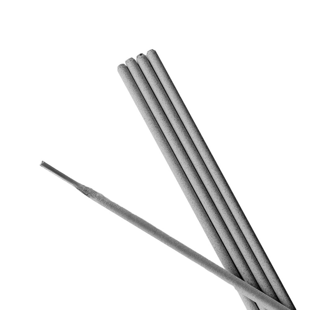
Washington Alloy 9018-M 10lbs Welding Stick Electrode (3/32″): Product Breakdown
“>
Washington Alloy 9018-M 10lbs Welding Stick Electrode (3/32″) is a low-hydrogen stick electrode intended for demanding structural and repair work where weld quality and toughness matter. The product description identifies it as an all-position, iron-powder electrode with manganese, molybdenum, and nickel, and notes it is aimed at low alloy, high tensile, quenched, and tempered steels such as T1, HY80, and HY90. That puts it in a class of consumables that buyers often choose for stronger base metals, but the final selection still depends on the job procedure, material condition, and code requirements.
This article breaks down what the product description tells you, what you should verify before use, and how to support the electrode in the shop. It is a buyer guide, not a procedure approval. If the job is code work, match the electrode to the WPS, base metal, joint design, and preheat/postheat requirements.
Key Takeaways
- 9018-M is described as an all-position, low-hydrogen, iron-powder electrode.
- The listed alloying elements are manganese, molybdenum, and nickel.
- It is intended for low alloy, high tensile, quenched, and tempered steels, including T1, HY80, and HY90 as listed by the source.
- The product description says weld deposits have excellent impact properties and are X-ray quality.
- Preheat and postheat are application dependent; exact requirements are Unknown (Verify).
What the Product Breakdown Means
The term low-hydrogen matters because hydrogen control is a common concern on higher-strength steels and restrained joints. In practical terms, the electrode should be stored and handled to limit moisture pickup. The listing also calls it iron-powder. That usually signals higher deposition efficiency than a plain general-purpose rod, but exact deposition behavior for this specific product is Unknown (Verify) unless you are working from the manufacturer data sheet or a qualified procedure.
The alloy content listed in the product summary suggests the rod is intended to support strength and toughness requirements. That does not mean it is the correct filler for every high-strength steel. Verify the base metal specification, thickness, restraint, service temperature, and any code or customer requirements before issuing it to production.
Practical Check / Inspect / Verify Steps
- Check the base metal spec and the job traveler. Confirm the material actually calls for a low-hydrogen high-strength electrode.
- Inspect the joint fit-up, bevel, root gap, and cleanliness. Remove rust, oil, mill scale, and moisture before striking an arc.
- Verify the required preheat and interpass controls. The source indicates preheating and postheating may be needed depending on thickness and hardening characteristics, but exact temperatures are Unknown (Verify).
- Check rod condition before use. Bent, contaminated, or moisture-exposed electrodes should not be treated as production-ready.
- Inspect the storage method. Low-hydrogen electrodes should be kept in a dry controlled environment or holding container as required by your procedure.
- Verify polarity and amperage from the manufacturer data or qualified procedure. Do not assume settings from another 9018-family rod transfer directly.
Troubleshooting Support for Shop Use
If the arc is unstable, the first checks should be basic. Inspect the electrode for moisture damage, verify the machine output, and confirm the work lead and stinger connections. If slag is difficult to remove, check travel speed and bead shape against the procedure. If cracking appears, stop and verify preheat, interpass control, restraint, and hydrogen management before continuing.
For operators using a stinger and holder, support gear matters. A worn holder jaw, loose cable connection, or poor ground can create heat loss and inconsistent arc behavior. If you need a refresher on holder setup and stick welding handling, see Welding Electrode Holder: Stinger Guide & Stick Welding Tips and Welding Electrode Holder: Choose the Best for Stick Welding.
Product / Parts Section
The product referenced here is Washington Alloy 9018-M 10lbs Welding Stick Electrode (3/32″). The provided source description indicates the rod is designed for low alloy, high tensile, quenched, and tempered steels and highlights impact performance and X-ray quality deposits. No further technical specifications were provided in the source set, so current diameter, length, current range, recovery rate, and storage limits are Unknown (Verify).
Use this product as a support item when your procedure and material call for this family of electrode. It is not a universal replacement for general-purpose rods. If you need a different structural stick option for comparison, a related support article on a 7014 electrode is available here: Washington Alloy 7014 Stick Electrode – Smooth Welding with High Deposition. That article is a selection reference, not a procedure approval.
Support Buying Notes
For maintenance buyers, the key question is not only whether the electrode is available, but whether it matches the weld requirement. Before buying, verify the joint type, service condition, and whether the job uses a qualified WPS. If purchasing for stock, label it by electrode family and keep usage notes by job type so the next shift does not have to guess. If the work mixes general fabrication and high-strength repair, separate the stock clearly to avoid mix-ups.
If you are also reviewing related equipment, the stinger and holder should be matched to expected duty and cable condition. A good electrode will not compensate for poor current transfer or damaged leads.
Safety Notes
- Follow the applicable WPS, SDS, and site hot-work rules.
- Keep low-hydrogen electrodes dry and protected from contamination.
- Use proper PPE, including eye, face, hand, and body protection.
- Do not assume preheat or postheat values; verify them for the specific job.
- Watch for fume control, especially in confined or poorly ventilated spaces.
FAQ
Is Washington Alloy 9018-M the same as every other 9018 rod?
No. The designation suggests a similar electrode family, but you should not assume identical performance, polarity, or settings. Verify against the manufacturer data and the job procedure.Can this rod be used on any high-strength steel?
No. The listing names certain high-strength and quenched-and-tempered steels, but actual suitability depends on the base metal, service conditions, and procedure approval. Verify before use.Does the listing guarantee X-ray quality welds?
No guarantee can be assumed from a product summary alone. The source says the deposits are X-ray quality, but the final result depends on fit-up, technique, cleanliness, parameters, and inspection requirements.What should I verify before putting it into production?
Check the WPS, base metal spec, preheat needs, storage condition, and current settings. Also verify that the joint prep and operator qualifications match the task.Sources Checked
- ArcWeld product page: Washington Alloy 9018-M 10lbs Welding Stick Electrode (3/32″)
- Internal WSP blog article: Welding Electrode Holder: Stinger Guide & Stick Welding Tips
- Internal WSP blog article: Welding Electrode Holder: Choose the Best for Stick Welding
- Internal WSP blog article: Washington Alloy 7014 Stick Electrode – Smooth Welding with High Deposition
Note: No WSP lookup page or filler metal finder page was provided for this draft. Technical details not present in the supplied sources are marked Unknown (Verify).
Related Arc Weld Part
Washington Alloy 9018-M 10lbs Welding Stick Electrode (3/32")
9018M is an all-position, low-hydrogen, iron-powder electrode containing manganese, molybdenum, and nickel. 9018M is designed for welding low alloy, high tensile, quenched, and tempered steels such as T1, HY80, and HY90. Weld deposits have excellent impact properties and are X-ray quality. PREHEATING AND POSTHEATING Depending upon the thickness and hardening characteristics of the workpiece, preheating at a temper…
View at Arc Weld StoreRelated Weld Support Guides
Washington Alloy 308L-16 Stick Electrode 10 LB. Package (3/32″ – 10 LBS.): Replacement Part Breakdown
Washington Alloy 308L-16 stick electrodes are commonly selected for stainless welding support work where an E308L-16 classification is being considered. For maintenance buyers and welders, the main job is not just finding a box with the right label. The job is verifying the base metal, joint condition, electrode size, storage condition, and the actual welding procedure before the part is issued to the floor.
This article is a practical breakdown for the Washington Alloy 308L-16 Stick Electrode 10 LB. Package (3/32″ – 10 LBS.) B08232Q6P7 product reference. It focuses on what to check, how to inspect the package and setup, and how to avoid ordering the wrong replacement item when the weld callout is incomplete or unclear.
Key Takeaways
- 308L-16 is a stainless stick electrode designation. Final procedure approval still depends on the job spec and base metal.
- The 10 lb package and 3/32″ diameter must both match the application and the holder setup.
- Do not assume stainless electrode interchangeability. Verify the alloy family, deposit requirements, and service environment.
- If the welding document is unclear, treat the selection as Unknown (Verify) until the procedure or supervisor confirms it.
What this product reference means
The product name identifies a Washington Alloy 308L-16 stick electrode in a 10 lb package, with a 3/32″ diameter noted in the title. Beyond that, details such as exact coating behavior, recommended polarity, packaging style, and any application limits are Unknown (Verify) unless confirmed by the governing spec, supplier data, or the job procedure.
For shop use, the important point is that the label alone is not a complete purchasing decision. Use the electrode classification as a starting point, then verify the following:
- Base metal grade and condition
- Required deposit chemistry
- Joint design and access
- Machine output range and stinger compatibility
- Storage and exposure history of the electrodes
Check before you buy
Inspect the weld callout. Confirm whether the job actually calls for 308L-16 or a different stainless electrode classification. If the print only says “stainless rod,” stop and verify. That instruction is not enough for a controlled purchase.
Verify diameter. The 3/32″ size must fit the amperage range, joint access, and operator skill level. If the work is thin material, tight corners, or positional welding, the diameter choice may need review. Unknown (Verify) until the procedure is checked.
Check the package count. A 10 lb box matters to stocking, issue control, and production planning. Make sure the order quantity aligns with burn rate and whether the electrode will be shared across jobs or kept for a single work order.
Inspect storage conditions. If the electrodes have been exposed to moisture, damaged packaging, or dirty storage, do not issue them blindly. Open package condition, visible contamination, and label integrity should be checked before use.
Troubleshooting and support checks
Problem: arc starts poorly or sticks excessively. Check the electrode holder, cable condition, machine settings, and the electrode condition itself. Verify that the current delivery is stable and that the rods are dry and clean. If the machine is correct but the issue remains, the procedure may be wrong for the material.
Problem: weld appearance is inconsistent. Inspect work lead placement, joint cleanliness, and travel control. Stainless stick work is sensitive to surface contamination. Check for mill scale, oil, paint, and oxide on the base metal. Verify that the joint was prepared to the required level before welding began.
Problem: the electrode seems to be the wrong choice. Stop and compare the job requirements to the product classification. Check whether the base material is stainless, whether dissimilar metal is involved, and whether corrosion resistance or service temperature requirements apply. If any of those are unclear, mark the selection Unknown (Verify) and escalate.
Problem: stock label does not match the work order. Inspect the carton label, internal part number, and issue documentation. Verify the ASIN reference only as a catalog identifier; do not treat it as a procedure approval.
Product and parts breakdown
The available product reference for this article is the Washington Alloy 308L-16 Stick Electrode 10 LB. Package (3/32″ – 10 LBS.) with ASIN B08232Q6P7. No additional part breakdown, kit contents, or accessory list is confirmed here. Unknown (Verify) for any claim about included extras, proprietary features, or special packaging beyond the stated product name.
For buyers, the practical breakdown is simple:
- Electrode classification: 308L-16
- Package size: 10 lb
- Diameter noted in title: 3/32″
- Catalog reference: B08232Q6P7
If your purchasing system requires a procedure match, job number, or approved filler list, verify those against internal documents before release.
Support links for selection checks
Use the WSP blog resources below as support references for stick welding setup and electrode handling. These are starting points for selection and shop practice, not guaranteed procedure approvals.
- Welding Electrode Holder: Stinger Guide & Stick Welding Tips
- Welding Electrode Holder: Choose the Best for Stick Welding
- Washington Alloy 7014 Stick Electrode – Smooth Welding with High Deposition
For broader stainless and filler selection work, compare the job requirements against the available WSP resources and internal purchasing controls. If the application is not clearly defined, do not guess.
Safety notes
- Verify the work area is ventilated before welding stainless materials.
- Check PPE condition before issue: helmet, gloves, jacket, and respiratory controls if required by site policy.
- Inspect the electrode holder and cables for damaged insulation before energizing the circuit.
- Keep electrodes dry and store them per site practice and manufacturer guidance when available.
- Do not use uncertain filler selection as a substitute for a qualified welding procedure.
FAQ
Is Washington Alloy 308L-16 the right electrode for any stainless job?
No. It may be suitable for some stainless applications, but the base metal, joint design, service condition, and procedure must be verified first.
Does the 3/32″ size work for every stick welding setup?
No. Diameter must match the machine output, joint access, and the required deposition rate. Verify before issue.
Can I use the Amazon product title as proof of procedure approval?
No. The title is a catalog reference only. Approval comes from the job spec, WPS, supervisor direction, or other controlled documentation.
What should I do if the exact filler requirement is unclear?
Mark it Unknown (Verify), check the print or WPS, and confirm with welding supervision or engineering before ordering or issuing the electrode.
Sources Checked
- Provided product reference: Washington Alloy 308L-16 Stick Electrode 10 LB. Package (3/32″ – 10 LBS.)
- Provided ASIN reference: B08232Q6P7
- Allowed internal links listed in the task
Matched Replacement Option
No products found.
Disclosure: As an Amazon Associate, Weld Support Parts may earn from qualifying purchases.
Related Weld Support Guides
When Welding Consumables Should Be Replaced
™-black-clearlight-4x-auto-darkening-welding-helmet-for-men-with-light-state-and-4-arc-sensors-welding-mask-with-13-4-sq-in-viewing-area-lightweight-welding-hood?utm_source=blog&utm_medium=internal&utm_campaign=when-welding-consumables-should-be-replaced”>
Welding consumable replacement is part of normal maintenance, not an emergency task. Consumables wear out from heat, spatter, arc exposure, and mechanical handling. The right replacement interval depends on process, amperage, duty cycle, base material, and operator technique.
Key Takeaways
- Replace consumables when wear affects arc stability, gas coverage, cut quality, or fit-up.
- Inspect consumables before each shift or job change.
- Do not run damaged tips, cups, nozzles, electrodes, liners, or rods past service limits.
- Replacement is based on condition, not a fixed calendar schedule.
- If performance drops suddenly, check the consumable first before changing settings.
When to Replace Welding Consumables
Replace a consumable when it no longer supports consistent weld quality or safe operation. Common signs include:
- Visible burn-back, cracks, distortion, or missing material
- Excessive spatter buildup that cannot be cleaned without damaging the part
- Loose fit, poor seating, or damaged threads
- Arc wandering, erratic starts, or unstable shielding
- Poor penetration, undercut, porosity, or inconsistent bead profile
- Reduced cut quality on plasma consumables
- Electrode contamination or tungsten degradation on TIG setups
Process-by-Process Replacement Guidance
MIG / GMAW
Common wear parts include contact tips, nozzles, diffusers, liners, drive rolls, and gun neck consumables. Replace them when wire feeding becomes inconsistent, the arc becomes unstable, or the tip bore is enlarged, ovaled, or burned. If the wire sticks, shaves, or birdnests repeatedly, inspect the liner and drive system before assuming the torch is at fault.
TIG / GTAW
Replace tungsten electrodes when the tip is contaminated, cracked, severely balled outside the intended process, or no longer grinds to a clean point or taper. Gas cups, collets, collet bodies, back caps, and torch bodies should be replaced if they are cracked, warped, or no longer hold components securely. If shielding is poor, check for leaks, loose parts, or damaged insulators.
Stick / SMAW
Stick electrodes are consumables by design and are used once. Replace unused electrodes if flux is damaged, damp, cracked, or contaminated. For electrode holders and cable connections, replace worn jaws, burned insulation, or damaged lugs if they affect current transfer or safety.
Plasma Cutting
Replace electrodes, nozzles, shields, swirl rings, and retaining caps when cut quality drops or the parts show erosion, double arcing, enlarged orifices, or heat damage. Plasma consumables are often replaced as a set when the wear pattern affects arc shape or kerf consistency.
Troubleshooting Before Replacement
If the weld or cut quality changes, verify these items before ordering parts:
- Correct current, polarity, and wire speed
- Proper gas type and flow rate
- Clean base metal and joint preparation
- Correct stickout, travel speed, and torch angle
- Drive roll tension and liner condition
- Leaks, loose fittings, or damaged cables
If the issue remains after these checks, the consumable is likely worn or damaged.
Replacement Triggers by Condition
- Arc instability: Replace contact tips, tungsten, nozzles, or plasma electrodes as applicable.
- Gas coverage loss: Inspect and replace cups, nozzles, diffusers, and seals.
- Feeding problems: Inspect liners, tips, drive rolls, and gun consumables.
- Heat damage: Replace parts that are warped, melted, or no longer concentric.
- Contamination: Replace parts that cannot be cleaned back to serviceable condition.
Product / Parts Section
For operators who need a clearer view of the arc and puddle during inspection or setup, the following product is available in the Weld Support Parts catalog:
- Miller Digital Infinity™ Black, ClearLight 4X Auto Darkening Welding Helmet —
Miller Digital Infinity™ Black, ClearLight 4X – Auto Darkening Welding Helmet for Men with Light State and 4 Arc Sensors – Welding Mask with 13.4 sq. in. Viewing Area – Lightweight Welding Hood
Experience Unmatched Clarity and Comfort with Miller Digital Infinity The Miller Digital Infinity auto darkening welding helmet features an industry-leading 13.4 sq. in. viewing area. This welding hood is designed to help ensure that welders enjoy unparalleled visibility and precision. You can say goodbye to tunnel vision with a welding shield specially crafted for high-performance tasks. Experience the difference…
View at Arc Weld Store
Product details not listed above are Unknown (Verify). Verify fit, process coverage, lens requirements, and compliance before purchase.
Safety Notes
- Lock out equipment before replacing torch, liner, or power components.
- Let hot parts cool before handling.
- Do not use cracked, melted, or loose consumables.
- Replace damaged gas cups, nozzles, and insulators before resuming work.
- Use the correct PPE for grinding, handling flux, and changing worn parts.
FAQ
How often should welding consumables be replaced?
There is no universal interval. Replace them when wear affects quality, feedability, shielding, or safety. Frequency depends on process and workload.
Should consumables be replaced as a set?
Sometimes. Plasma consumables are often changed together when wear is advanced. MIG and TIG parts may be replaced individually if only one component is worn.
Can I keep using a worn contact tip or nozzle?
Not if it affects arc performance or gas coverage. Small wear can quickly become a defect or a shutdown.
What is the first part to check when weld quality changes?
Check the consumable, then verify gas, settings, workpiece prep, and cable condition.
Sources Checked
- When to Use 7018 vs 7014 Welding Rods: Differences, Similarities, Pros & Cons
- Welding with 7018: Should You Use AC or DC Current? When to Use 7018AC
- How to Identify and Replace Compatible TIG Torch Consumables for Optimal Welding Performance
- Aluminum ER 5554 3/64″ X 5lb. MIG Welding Wire Spool By Washington Alloy – Weld Support Parts Blog
Related Weld Support Guides
- Aluminum ER 5554 3/64″ X 5lb. MIG Welding Wire Spool By Washington Alloy – Weld Support Parts Blog
- When to Use 7018 vs 7014 Welding Rods: Differences, Similarities, Pros & Cons
- Welding with 7018: Should You Use AC or DC Current? When to Use 7018AC
- How to Identify and Replace Compatible TIG Torch Consumables for Optimal Welding Performance


