Tag: shielding gas

  • 211 Pro MIG Weld Porosity Troubleshooting: MDX-100 Gas Coverage, Nozzle, and Setup Checks

    If a 211 Pro MIG weld has pinholes, worm tracks, black soot, popping starts, or porous spots after grinding, check shielding coverage before changing wire speed or blaming the machine. On the Millermatic 211 PRO, the standard gun path is the MDX-100 with AccuLock MDX consumables, so porosity troubleshooting should start at the gas cylinder, regulator, gas hose, machine gas valve, MDX-100 gun connection, diffuser, nozzle, contact tip, and weld surface condition.

    Porosity is trapped gas in the weld. The cause may be no gas, low gas, too much turbulent gas, wind, a blocked nozzle, a clogged diffuser, a loose fitting, wrong shielding gas, damp/dirty base metal, contaminated wire, or poor gun angle. A flowmeter can show gas moving while the weld puddle still has poor shielding at the arc.

    Common Symptoms

    • Pinholes in the bead: Usually shielding loss, contamination, or gas trapped in the weld pool.
    • Porosity after grinding: The surface looked acceptable, but internal holes were exposed.
    • Black soot around the weld: Gas coverage, gas mix, stickout, or base metal cleanliness is suspect.
    • Popping starts: Gas delay, poor ground, bad tip, or contaminated wire end can cause unstable starts.
    • Porosity near the end of a weld: Gas coverage may be lost as travel speed, angle, or stickout changes.
    • Porosity only outdoors: Wind is blowing shielding gas away from the puddle.
    • Porosity only after several welds: Nozzle or diffuser may be loading with spatter.

    What This Failure Means

    MIG shielding gas must protect the molten puddle until the metal solidifies. If air reaches the puddle, oxygen, nitrogen, and moisture can enter the weld and leave visible or hidden pores. On a 211 Pro, this can happen even when the welder feeds wire normally. Do not diagnose porosity only as a wire-feed problem unless burnback, stutter, or birdnesting is also present.

    Compatibility Notes

    The Millermatic 211 PRO package uses the MDX-100 gun family. Use MDX-100 / AccuLock MDX nozzles, tips, diffusers, and liners unless the gun has been physically changed. The Miller MDX-100 gun parts page is the correct parts breakdown direction. Do not use Lincoln Magnum, Tweco, Bernard Centerfire, or Miller M-Series consumables on an MDX-100 unless fitment is independently verified.

    Fast Porosity Checks Before Replacing Parts

    1. Confirm the cylinder valve is open and the cylinder is not empty.
    2. Verify the shielding gas matches the process: C25 or CO2 for mild steel MIG, correct stainless mix for stainless, and argon for aluminum spool gun work.
    3. Pull the trigger and confirm gas flow at the MDX-100 nozzle.
    4. Inspect the nozzle bore for spatter, slag, or anti-spatter buildup.
    5. Inspect the AccuLock MDX diffuser gas ports for blockage or damage.
    6. Check that the contact tip is tight, correct for wire size, and not burned back.
    7. Remove fans, drafts, and open-door airflow from the weld area.
    8. Clean the base metal to bright metal where the arc and gas coverage will be.

    Porosity Diagnosis Table

    SymptomLikely CauseFirst Check
    No gas sound at nozzleClosed cylinder, empty cylinder, blocked line, gas valve issueCheck cylinder and regulator flow
    Gas sound present but porous beadLeak, wind, blocked nozzle, wrong gas, contaminationCheck nozzle, diffuser, fittings, gas type
    Porosity only outdoorsShielding gas blown awayUse wind protection or change process
    Porosity after welding for a whileNozzle/diffuser spatter buildupRemove front end and inspect gas path
    Porosity at startsGas delay, long stickout, dirty wire end, bad tipTrim wire and check tip/nozzle
    Porosity with high gas flowTurbulence pulling air into gas streamReduce flow and check nozzle size

    MDX-100 Front-End Items That Cause Porosity

    • Nozzle: Spatter narrows the gas path and disturbs shielding around the puddle.
    • Diffuser: Blocked gas ports can send gas unevenly through the nozzle.
    • Contact tip: A burned or loose tip creates unstable arc length and poor starts.
    • Liner: A restricted liner can cause feed stutter that makes gas coverage look inconsistent.
    • Gun connection: A poor seat or damaged seal can leak gas before it reaches the nozzle.

    Base Metal and Wire Contamination Checks

    Clean metal matters. Mill scale, paint, oil, cutting fluid, rust, zinc coating, moisture, marker residue, and anti-spatter overspray can all create porosity. Clean both sides of a joint when possible, especially on lap joints, tubing, and repaired material where contamination can vent into the puddle from underneath.

    Gas Flow Notes

    Use the machine, wire, and gas supplier guidance as the final reference. For short-circuit MIG on mild steel, many shop setups run in a moderate CFH range, but the correct setting depends on gas mix, nozzle bore, stickout, joint access, amperage, and air movement. Do not fix wind by turning the flowmeter excessively high. High flow can create turbulence and pull air into the shielding envelope.

    Common Wrong-Setup Mistakes

    • Running solid wire with the gas cylinder closed.
    • Using 100% argon on mild steel short-circuit MIG.
    • Using a gasless flux-core nozzle while trying to weld with shielding gas.
    • Leaving fans or open doors blowing across the weld.
    • Welding over oil, paint, mill scale, rust, or moisture.
    • Using non-MDX front-end consumables on an MDX-100 gun.
    • Turning gas flow too high and creating turbulence.
    • Replacing drive rolls when the actual problem is gas coverage or contamination.

    Test Procedure

    1. Install a clean, correct-size AccuLock MDX contact tip.
    2. Remove and clean or replace the MDX nozzle.
    3. Inspect the diffuser and replace it if gas ports are blocked or damaged.
    4. Confirm gas flow at the nozzle with the trigger pulled.
    5. Check external gas fittings with leak-detection solution or soapy water.
    6. Clean scrap steel to bright metal and weld indoors with drafts removed.
    7. If the clean indoor test weld is sound, the machine is likely not the root cause.
    8. If porosity remains, isolate gas supply, regulator, hose, gun connection, and machine gas valve.

    Field Fix vs Proper Fix

    Field fix: Clean the nozzle, replace the contact tip, block drafts, confirm gas flow, trim the wire, and test on clean scrap.

    Proper fix: Replace damaged MDX-100 front-end parts, repair leaks, verify gas type, clean the work properly, correct stickout and gun angle, and document the gas/wire/material setup that produces a sound test weld.

    Related Failure Paths

    Safety Notes

    • Secure shielding gas cylinders upright.
    • Do not use damaged regulators, hoses, or fittings.
    • Keep your head out of fumes and use ventilation.
    • Do not weld coated, oily, or unknown material without identifying hazards.
    • Disconnect input power before internal machine service.
  • TIG Tungsten Contamination Troubleshooting: Black Specks, Arc Wander, Dirty Starts, and Re-Grind Checks

    TIG tungsten contamination usually comes from one of five places: the tungsten touched the puddle, the filler rod hit the electrode, shielding gas was interrupted, the tungsten was ground on a dirty wheel, or the torch consumables are leaking or loose. The fix is not to keep welding through it. Stop, cut back or re-grind the contaminated tungsten, verify gas coverage, inspect the collet/gas lens/cup, and test on clean scrap before returning to the part.

    Contaminated tungsten can show up as black specks in the bead, gray or black weld edges, arc wandering, hard starts, sputtering, excessive balling, or a weld puddle that will not stay centered. On critical work, assume the contaminated section of weld may need to be removed and re-welded. Do not treat tungsten inclusions as cosmetic.

    Common Symptoms

    SymptomLikely CauseFirst Check
    Black specks in beadTungsten dipped or flaked into puddleInspect tip under good light
    Arc wanders or splitsDirty grind, off-center point, contaminated tipRe-grind lengthwise on clean wheel
    Gray/black weld surfacePoor shielding, long stickout, post-flow too shortCheck argon flow, leaks, cup, gas lens
    Tungsten balls excessivelyToo much amperage for diameter, wrong polarity/process setupVerify tungsten size, type, current, polarity
    Tungsten slipsWorn collet or collet bodyPull-test electrode after tightening

    Fast Diagnosis Procedure

    1. Stop welding immediately. Do not keep running a bead after dipping the tungsten.
    2. Remove the tungsten. Look for melted filler, dark oxidation, a balled end, cracks, or an off-center point.
    3. Cut back if dipped. If base metal or filler is fused into the tip, cut off the bad section before grinding.
    4. Re-grind lengthwise. Grind marks should run with the electrode, not around it.
    5. Check gas coverage. Verify cylinder valve, regulator, hose leaks, torch O-rings, cup condition, and post-flow.
    6. Inspect torch consumables. Replace cracked cups, loose collets, damaged gas lenses, and worn collet bodies.
    7. Run a scrap test. Use clean scrap, same filler, same amperage, and same torch angle before returning to the job.

    What Wears Out First

    The tungsten tip gets blamed first, but the support parts often cause repeat contamination. A worn collet can let the electrode move. A damaged collet body can create poor current transfer. A clogged or damaged gas lens can disturb shielding gas. A cracked cup can pull air into the weld zone. A loose back cap or damaged rear seal can also create gas problems that look like bad tungsten prep.

    Inspection Steps

    • Tungsten: verify diameter, alloy/color code, grind direction, point symmetry, and contamination at the tip.
    • Collet: confirm it matches the tungsten diameter and grips without over-tightening.
    • Collet body/gas lens: inspect threads, seating face, screen condition, and gas flow path.
    • Cup: check for cracks, spatter, chips, or poor seating.
    • Gas system: confirm argon, hose condition, regulator flow, torch leaks, and post-flow time.
    • Base/filler metal: clean oil, oxide, mill scale, moisture, coating, and grinder residue before blaming the machine.

    Common Wrong-Part Mistakes

    • Buying a collet that does not match tungsten diameter.
    • Using a standard collet body when the cup setup requires a gas lens body.
    • Mixing torch series parts between 9/20 and 17/18/26-style torches.
    • Assuming all cups fit all torch heads.
    • Ordering tungsten by color only without confirming diameter, current type, and application.
    • Replacing tungsten repeatedly while leaving a worn collet body or leaking cup in service.

    Compatibility Notes

    Before ordering TIG support parts, verify torch series, tungsten diameter, cup thread/style, gas lens or standard collet body, back cap length, power connector, cooling type, amperage range, and process polarity. Lincolnโ€™s parts guide identifies TIG torch support items such as tungsten electrodes, collets, collet bodies, gas lens collet bodies, alumina nozzles, back caps, and connection adapters. Match by torch family and consumable system, not by appearance alone.

    Field Fix vs Proper Fix

    ConditionField FixProper Fix
    Dipped tungstenStop and re-grindCut back contaminated section, re-grind, remove affected weld if required
    Dirty grind wheelUse clean side of wheelUse dedicated tungsten grinder or dedicated wheel
    Cracked cupReplace cupInspect full front-end stack for gas leakage
    Worn colletInstall spare colletReplace collet and inspect collet body threads/taper
    Oxidized tungsten after stopIncrease post-flowVerify post-flow setting, torch leak points, and gas purity

    Related Failure Paths

    Safety Notes

    Wear eye, hand, and respiratory protection appropriate for welding and tungsten grinding. Use local extraction when grinding tungsten dust. Allow hot torch parts to cool before handling. If thoriated tungsten is used, follow your employerโ€™s safety procedure and SDS requirements. For code, sanitary, pressure, aerospace, or structural work, follow the applicable WPS and inspection requirements before accepting or repairing a contaminated weld.

  • How to Stop MIG Nozzle Spatter from Blocking Gas Coverage

    MIG weld porosity is often blamed on shielding gas settings, but a blocked nozzle can cause the same problem. When spatter builds up inside the MIG gun nozzle, shielding gas flow can become restricted, uneven, or turbulent. The result may be pinholes, black soot, erratic arc behavior, and poor bead appearance.

    This guide explains how nozzle spatter buildup causes gas coverage problems, what to check first, and how to clean and prevent buildup without damaging the gun consumables.

    Key Takeaways

    • Spatter inside the MIG nozzle can restrict shielding gas and cause porosity.
    • A nozzle that looks acceptable from the outside may be blocked internally.
    • Nozzle gel can reduce spatter adhesion, but it should not be over-applied.
    • Contact tip, diffuser, and nozzle condition should be checked together.
    • Porosity troubleshooting should include gas leaks, flow rate, wind, base metal cleanliness, and consumable buildup.

    Problem / Context

    A MIG nozzle collects spatter during normal welding. If the buildup is not removed, it can narrow the gas path around the contact tip and diffuser. Shielding gas may still be flowing at the regulator, but the gas envelope at the weld puddle may be weak or uneven.

    This issue is common when welding with short-circuit transfer, welding in tight corners, using excessive wire stickout, welding on dirty material, or running settings that create heavy spatter. It can also happen when the nozzle is dipped too deeply into anti-spatter compound.

    Root Causes

    • Internal nozzle buildup: Spatter collects inside the nozzle and blocks the gas path.
    • Dirty diffuser: Spatter or debris around diffuser holes disrupts gas flow.
    • Damaged contact tip: A worn or oversized tip can cause unstable wire feeding and more spatter.
    • Excessive nozzle gel: Too much compound can contaminate the nozzle, contact tip, or weld area.
    • Incorrect settings: Voltage, wire speed, stickout, and travel angle can all affect spatter level.
    • External gas problems: Wind, leaks, low cylinder pressure, incorrect gas mix, or poor flow rate can also cause porosity.

    Solution

    Remove the nozzle and inspect the inside, not just the outside edge. If spatter is narrowing the opening or covering diffuser holes, clean the nozzle before adjusting the machine. Use proper MIG pliers or a nozzle cleaning tool rather than striking the nozzle against the workbench.

    • Turn off the welder before removing or servicing gun consumables.
    • Remove the nozzle and clear spatter from the inside wall.
    • Inspect the contact tip for wear, burnback, keyholing, or blocked wire passage.
    • Check the diffuser or gas ports for spatter blockage.
    • Reinstall consumables securely without cross-threading.
    • Apply nozzle gel lightly if used, keeping it away from the contact tip bore and weld joint.
    • Run a short test weld and inspect for porosity before continuing production work.

    Specs / Verification Notes

    Item to VerifyWhat to CheckNotes
    MIG gun modelNozzle, tip, and diffuser compatibilityUnknown (Verify)
    Wire sizeContact tip size matches wire diameterUnknown (Verify)
    Shielding gasCorrect gas or gas mix for processUnknown (Verify)
    Gas flowFlow at the gun, not only at the regulatorUnknown (Verify)
    Nozzle conditionInternal spatter, deformation, loose fitReplace if damaged
    Diffuser conditionBlocked gas holes or damaged threadsReplace if damaged

    Product Section

    Nozzle gel can help reduce weld spatter adhesion inside a MIG nozzle. It should be used as a support item, not as a substitute for correct settings, clean consumables, and proper shielding gas coverage. Verify current product size, seller, and safety information before purchase.

    Last update on 2026-07-14 / Affiliate links / Images from Amazon Product Advertising API

    Comparison Table

    ApproachBest UseRisk
    Routine nozzle cleaningDaily MIG gun maintenanceMay be skipped when production is rushed
    Nozzle gelReducing spatter adhesionOver-application can create contamination risk
    Replacing nozzleDamaged, distorted, or heavily packed nozzleWrong nozzle can affect gas coverage
    Changing weld settingsReducing excessive spatter at the sourceIncorrect changes can create new weld defects

    Safety Notes

    • Allow the nozzle and contact tip to cool before handling. MIG gun front-end parts can remain hot after welding.
    • Use safety glasses when removing spatter because fragments can break loose during cleaning.
    • Follow the product SDS for nozzle gel or anti-spatter compound handling and storage.
    • Keep anti-spatter compounds away from open flames unless the product documentation confirms safe use conditions.
    • Follow OSHA welding, cutting, and brazing requirements and ANSI Z49.1 safety guidance for welding, cutting, and allied processes.

    FAQ

    Can nozzle spatter cause MIG porosity?

    Yes. Heavy spatter buildup inside the nozzle can interfere with shielding gas coverage and contribute to porosity.

    How often should a MIG nozzle be cleaned?

    Clean it whenever spatter buildup is visible inside the nozzle or when weld quality changes. High-spatter applications may require frequent cleaning during the job.

    Can too much nozzle gel cause problems?

    Yes. Excessive gel can collect debris or contaminate the contact tip and work area. Use a light amount and keep it out of the wire path.

    Should the contact tip be replaced when cleaning the nozzle?

    Inspect it at the same time. Replace the contact tip if it is worn, blocked, burned back, loose, or no longer feeding wire consistently.

    What should be checked if the nozzle is clean but porosity remains?

    Check gas flow at the gun, gas leaks, wind, base metal contamination, wire condition, polarity, and the correct gas type for the wire and process.

    Next Step

    If MIG porosity appears suddenly, remove the nozzle and inspect the gas path before changing the welder settings. Clean the nozzle, check the diffuser and contact tip, verify gas flow, then make a short test weld on clean material.

    Sources Checked

    • Amazon product page for Forney Nozzle Gel 16 Oz, ASIN B00IOX4GBE
    • OSHA 1910.252 welding, cutting, and brazing general requirements
    • OSHA Eye Protection against Radiant Energy during Welding and Cutting fact sheet
    • AWS Eye and Face Protection for Welding and Cutting Operations fact sheet
    • ANSI Z49.1 safety guidance for welding, cutting, and allied processes
  • Why Your TIG Weld Is Getting Contaminated (And How to Fix It)

    TIG contamination shows up as a dull, dirty weld, unstable arc, or blackened tungsten. Itโ€™s usually caused by poor shielding, dirty material, or tungsten issues, and it will quickly ruin weld quality if not corrected.

    Key Takeaways

    • Contamination is usually caused by air exposure or dirty surfaces
    • Tungsten condition directly affects arc stability
    • Shielding gas problems are a top cause
    • Cleanliness is critical for TIG welding success

    Whatโ€™s Causing the Problem

    1) Poor Shielding Gas Coverage

    • Gas flow is too low or disrupted
    • Drafts pulling shielding gas away
    • Leaks in hoses or fittings

    2) Dirty Base Material

    • Oil, grease, oxidation, or coatings
    • The aluminum oxide layer was not removed
    • Stainless contamination from improper tools

    3) Contaminated Tungsten

    • Touching the puddle or filler rod
    • Improper grinding direction
    • Using the wrong tungsten type for the job

    4) Incorrect Gas Flow Settings

    • Too low โ†’ inadequate shielding
    • Too high โ†’ turbulence pulling in air

    5) Bad Technique

    • Long arc length exposing the weld to the atmosphere
    • Improper torch angle
    • Inconsistent filler rod feeding

    How to Fix It

    Step 1: Set Proper Gas Flow

    • Typical range: 15โ€“25 CFH (7โ€“12 L/min)
    • Use lower end indoors, higher if needed for coverage

    Step 2: Clean the Material Thoroughly

    • Use a dedicated stainless steel brush for aluminum/stainless steel
    • Remove all oil and grease with acetone
    • Grind or wire brush to clean the metal surface

    Step 3: Prepare Tungsten Correctly

    • Grind longitudinally (not around)
    • Keep a sharp, clean point for DC welding
    • Replace tungsten if contaminated

    Step 4: Check Equipment

    • Inspect gas lines and connections for leaks
    • Clean the nozzle and check the gas lens if installed
    • Ensure proper cup size for coverage

    Step 5: Improve Technique

    • Keep arc length short and consistent
    • Maintain proper torch angle (~10โ€“15ยฐ)
    • Feed the filler rod smoothly without touching the tungsten

    Common Mistakes to Avoid

    • Welding on dirty or oxidized metal
    • Letting tungsten touch the weld puddle
    • Running gas flow too high or too low
    • Using contaminated filler rods
    • Ignoring drafts in the work area

    Best Settings / Guidelines

    ParameterTypical Range
    Gas Flow15โ€“25 CFH (7โ€“12 L/min)
    Arc LengthShort and consistent
    Torch Angle10โ€“15ยฐ
    Tungsten PrepSharp point (DC), clean grind
    Filler RodClean, matched to material

    Always verify with your machine settings and material requirements.

    Safety Notes

    • Wear proper eye protection (ANSI Z87.1) and a welding helmet
    • Avoid breathing shielding gas in confined areas
    • Use proper ventilation when cleaning with solvents
    • Keep gloves clean to prevent contaminating filler rods

    FAQ

    Why does my tungsten turn black?
    This usually indicates poor shielding gas coverage or contamination.

    Can I reuse contaminated tungsten?
    Yes, but it must be re-ground properly before reuse.

    Does gas type matter for contamination?
    Yesโ€”pure argon is standard for TIG and provides proper shielding.

    Why is aluminum more prone to contamination?
    Aluminum forms an oxide layer that must be removed before welding.

    Can drafts really affect TIG welding?
    Yesโ€”even small air movement can disrupt shielding gas.

    Sources Checked

    • American Welding Society
    • Lincoln Electric TIG welding resources
    • Miller Electric application and troubleshooting guides

  • Why Your MIG Weld Has Porosity (and How to Fix It Fast)

    Porosity in MIG welding shows up as pinholes or small voids in the weld bead. It weakens the weld and usually points to shielding gas failure or contamination. This guide breaks down the exact causes and the fastest way to fix it using proper setup and wire selection.

    Key Takeaways

    • Porosity is caused by poor shielding gas coverage or contamination
    • Dirty metal and bad wire are the most common causes
    • Gas flow, nozzle condition, and wire choice fix most issues
    • ER70S-6 wire helps reduce porosity on less clean steel

    What Causes MIG Weld Porosity

    Porosity occurs when atmospheric gases get trapped in the weld pool as it solidifies. In MIG welding, shielding gas is supposed to prevent this. When coverage fails, defects form.

    • Low shielding gas flow
    • Wind or airflow disrupting gas
    • Dirty or oily metal
    • Rusty or contaminated wire
    • Improper stickout or angle
    • Clogged nozzle or diffuser

    How to Fix MIG Porosity

    • Set gas flow to 20โ€“30 CFH (verify for your setup)
    • Keep stickout around 3/8โ€โ€“1/2โ€
    • Clean metal to bare steel
    • Check for gas leaks
    • Replace worn nozzle or diffuser
    • Switch to ER70S-6 wire if needed

    Recommended Wire for Reducing Porosity

    Hobart ER70S-6 MIG Welding Wire (.030โ€)


    Type: Solid MIG wire

    Diameter: .030โ€

    Material: Mild steel

    Deoxidizers: Higher than ER70S-3

    Specs: Unknown (Verify)

    Hobart H305406-R22 10-Pound ER70S-6 Carbon-Steel Solid Welding Wire, 0.030-Inch
    • Carbon-steel sound, porosity-free welds with powerful deoxidizers for your work with shielding gases.
    • Great for construction work, farm implement fabrication, shaft buildup, tanks, truck bodies and general shop applications with poor fit-up or rusty, oily plates.
    • 10-Pound spool
    • Country of Origin: Made in China

    Last update on 2026-07-14 / Affiliate links / Images from Amazon Product Advertising API


    ER70S-6 wire is more forgiving on dirty steel and helps reduce porosity compared to ER70S-3.

    Gas Flow Setup

    • Typical: 20โ€“30 CFH (verify)
    • Too low = poor coverage
    • Too high = turbulence
    • Avoid drafts when welding

    Wire Comparison

    WireKey DifferenceBest Use
    ER70S-6More deoxidizersDirty steel
    ER70S-3Cleaner arcClean material

    Safety Notes

    Use ANSI Z87.1 compliant eye protection and proper PPE. Ensure ventilation and follow AWS welding safety guidelines.

    FAQ

    Q: Can too much gas cause porosity?
    A: Yes. It can create turbulence and pull in air.

    Q: Does wire matter?
    A: Yes. ER70S-6 is more forgiving on dirty steel.

    Next Step

    Check your gas flow and nozzle first. If needed, switch to ER70S-6 wire and clean your material before welding.

  • Best TIG Gas Lens Kit for Sooty Welds (Clean Shielding)

    Black soot and dirty tungsten usually point back to shielding gas coverageโ€”either turbulence, leaks, or a setup that canโ€™t maintain a stable argon envelope. A gas lens kit is one of the simplest upgrades to stabilize coverage, especially with longer stickout or tight joints.
    Not sure if this is your issue? See the full troubleshooting guide โ†’ TIG Welds Turning Black and Sooty? Fix Gas Coverage Fast

    STARTECHWELD 45V26 TIG Gas Lens 3/32โ€ Gas Lens collet body Fit TIG WP17, WP18, WP26 (5 Pack) 45V26
    • TIG Gas Lens 45V26 Tig Torch Gas Lens 3/32โ€
    • Work With: TIG 17, 18, 26 Series Torches
    • 3/32″ Tungsten Electrodes Standard 10N Series Collet
    • 54N Series Gas Lens Ceramic Cups Setup
    • Pack of 5

    Last update on 2026-07-14 / Affiliate links / Images from Amazon Product Advertising API

    Key Takeaways

    • A gas lens helps create more stable, laminar shielding gas flow
    • Better coverage can reduce soot, oxidation, and tungsten contamination
    • Match the kit to your torch family (commonly 17/18/26 style)
    • Replace damaged screens/cupsโ€”dirty hardware can cause โ€œmysteryโ€ contamination
    • If specs arenโ€™t clearly listed, treat it as Unknown (Verify) before buying

    Product Picks (verify fitment before ordering)

    1) 45V26 TIG Gas Lens (3/32 in) โ€” TOP PICK (Most common fix)

    Short description: A standard 45V26-reference gas lens collet body for common 17/18/26-style TIG torches.
    Key specs (manufacturer verified): Ref number 45V26; intended for 3/32 in (2.4 mm) tungsten; torch family 17/18/26 (Verify exact torch compatibility).
    Best for: Most welders seeing soot/dirty tungsten after switching cups, changing stickout, or fighting inconsistent coverage.
    ArcWeld link: N/A
    Amazon:

    STARTECHWELD 45V26 TIG Gas Lens 3/32โ€ Gas Lens collet body Fit TIG WP17, WP18, WP26 (5 Pack) 45V26
    • TIG Gas Lens 45V26 Tig Torch Gas Lens 3/32โ€
    • Work With: TIG 17, 18, 26 Series Torches
    • 3/32″ Tungsten Electrodes Standard 10N Series Collet
    • 54N Series Gas Lens Ceramic Cups Setup
    • Pack of 5

    Last update on 2026-07-14 / Affiliate links / Images from Amazon Product Advertising API

    2) 17/18/26 Gas Lens Kit (cups + lens + collets)

    Short description: A bundled kit can be the fastest way to replace multiple wear items at once (cups, collets, lens).
    Key specs: Unknown (Verify)
    Best for: If your cup is chipped, your lens screen is dirty, and you want a clean reset.
    ArcWeld link: N/A
    Amazon:
    Unknown (Verify)

    Still deciding? Compare these options below.

    STARTECHWELD 45V26 TIG Gas Lens 3/32โ€ Gas Lens collet body Fit TIG WP17, WP18, WP26 (5 Pack) 45V26
    • TIG Gas Lens 45V26 Tig Torch Gas Lens 3/32โ€
    • Work With: TIG 17, 18, 26 Series Torches
    • 3/32″ Tungsten Electrodes Standard 10N Series Collet
    • 54N Series Gas Lens Ceramic Cups Setup
    • Pack of 5

    Last update on 2026-07-14 / Affiliate links / Images from Amazon Product Advertising API

    3) Jumbo Cup Gas Lens Kit (for longer stickout)

    Short description: Larger cups can improve coverage in joints where you need extra tungsten stickout.
    Key specs: Unknown (Verify)
    Best for: Corners, fillets, and tight access where coverage breaks down.
    ArcWeld link: N/A
    Amazon:
    Unknown (Verify)

    Buying Guide: How to Choose

    • Torch family fit (17/18/26 vs other): Donโ€™t assumeโ€”verify your torch style before ordering.
    • Tungsten diameter: Match the lens/collet body to your tungsten size (common: 1/16 in, 3/32 in, 1/8 in).
    • Cup size and access: Bigger cups can help coverage but may not fit tight joints.
    • Quality and consistency: If listings donโ€™t clearly state reference numbers (like 45V26) and fitment, treat as Unknown (Verify).

    FAQ

    What does a gas lens actually change?
    It helps straighten and stabilize gas flow, so coverage is less turbulent and more consistent.

    Can too much gas cause soot?
    Yes. Excess flow can create turbulence that pulls air into the shield.

    Do I still need to regrind tungsten after soot shows up?
    Yes. Once contaminated, itโ€™s faster and more reliable to regrind than to โ€œburn it clean.โ€

    Will a gas lens fix leaks or bad gas?
    No. Fix leaks, confirm 100% argon, and check connections first.

    Safety Notes

    Use appropriate PPE and ensure eye protection meets ANSI Z87.1. Maintain ventilationโ€”shielding issues can tempt people to hover and โ€œtestโ€ the arc repeatedly, increasing UV exposure.

  • TIG Welds Turning Black and Sooty? Fix Gas Coverage Fast

    If your TIG welds are coming out black, sooty, or โ€œdirty,โ€ youโ€™re not aloneโ€”this is one of the most common early warning signs of shielding gas problems. It usually shows up mid-bead when everything seems set correctly. Hereโ€™s why it happens and how to fix it.

    Symptoms (what youโ€™ll see)

    • Black soot around the bead (sometimes a โ€œsmoke trailโ€ look)
    • Tungsten turns dark/sooty or balls up unexpectedly
    • Porosity starts showing up even on clean steel
    • Arc feels unstable or wanders
    • Weld color looks dull/gray instead of clean and consistent

    Root cause (whatโ€™s actually happening)

    Black soot is typically a sign that your weld puddle (and/or hot tungsten) is seeing oxygen and contaminants because shielding gas coverage is breaking down. That can come from too little flow, turbulent flow, a leak, a blocked cup/screen, or drafts pulling the argon away.

    On steel, poor shielding can leave soot and surface oxidation; on stainless, it can show up as heavy discoloration; on aluminum, it often stacks with porosity and โ€œdirtyโ€ looking puddle behavior. The key point: argon has to form a stable envelope around the tungsten and puddleโ€”when it doesnโ€™t, contamination happens fast.

    The fix (step-by-step)

    1. Check flow rate and stop turbulence
      Start around 15โ€“20 CFH (0.42โ€“0.57 mยณ/h) for typical cups, then adjust. Too low starves coverage; too high can create turbulence that pulls air in.
    2. Inspect the cup, collet body, and gas lens screen
      Remove the cup and look for spatter, dust, or a partially blocked gas lens screen. If the screen is dirty or damaged, replace it.
    3. Leak-check the gas path
      Confirm tight connections from the regulator to the torch. If you suspect leaks, isolate sections (regulator, hose, torch) and re-test. Leaks can cause inconsistent shielding and โ€œrandomโ€ soot.
    4. Increase stickout control (or switch to a gas lens)
      If youโ€™re running long tungsten stickout (common in corners/fillets), a standard setup can lose coverage. A gas lens helps laminar flow and supports longer stickout without losing shielding.
    5. Fix post-flow and regrind tungsten
      If the tungsten is sooty/contaminated, stop and regrind. Also ensure post-flow is long enough to protect the tungsten as it cools.

    Safety note during troubleshooting

    If youโ€™re chasing shielding issues, donโ€™t โ€œtestโ€ by hovering the torch and blasting gas near your face. Keep your hood down and gloves onโ€”hot tungsten and UV exposure are still hazards even during quick checks.

    Real-world tip (what experienced welders do)

    When soot shows up, experienced TIG welders donโ€™t keep pushing the bead hoping it clears. They stop, regrind the tungsten, and do a fast gas-system sanity check: flow, leaks, cup/lens condition, and drafts. If theyโ€™re working with longer stickout or tight joints, they often move straight to a gas lens setup because it reduces sensitivity to small technique changes.

  • Bad Gas Coverage in MIG Welds? Replace Your Nozzle

    Intro

    Your MIG welds are porous, and you can see the problem: the shielding gas isn’t covering the weld pool. The arc is exposed, hydrogen from the air contaminates the molten metal, and porosity results. The fix isn’t always a regulator adjustmentโ€”it’s often a worn or wrong nozzle. A damaged nozzle restricts gas flow and creates dead zones where the arc isn’t protected. This guide shows you how to diagnose and fix it in 5 minutes.

    Key Takeaways

    • A worn or wrong nozzle restricts gas flow and causes porosity
    • Copper nozzles conduct heat better and last longer than steel
    • Nozzle orifice size affects gas coverage (5/8″ is standard for most MIG guns)
    • Replace nozzles every 100โ€“150 hours of welding or when spatter buildup is visible
    • Always clean the nozzle before replacing itโ€”spatter can be deceptive

    The Problem

    A MIG nozzle is a copper tube that directs shielding gas around the arc. Over time, spatter welds itself to the nozzle, restricting the gas opening. When the orifice is blocked or worn, gas coverage becomes inconsistent.

    What happens:

    • Reduced gas flow: Spatter buildup narrows the opening, starving the arc of protection.
    • Dead zones: Gas doesn’t reach the entire weld pool, leaving unprotected areas.
    • Hydrogen absorption: Unshielded molten metal absorbs hydrogen from air, creating porosity.
    • Weak welds: Porosity reduces tensile strength and can fail inspection.

    You’ll see:

    • Porosity clustered in the weld center or edges
    • Spatter stuck to the nozzle (sometimes thick)
    • Dull or inconsistent arc appearance
    • Gas leaks or hissing sounds around the gun

    Why It Matters

    Porosity is a weld defect. In structural work, it can fail X-ray or ultrasonic inspection. In production, rework costs time and material. A $5 nozzle replacement prevents hours of grinding and rewelding. It also improves weld aesthetics and reduces spatter cleanup.

    The Fix

    1. Power down the welderย and wait 30 seconds.
    2. Unscrew the nozzleย from the gun (usually hand-tight or one-quarter turn).
    3. Inspect the nozzleย for spatter buildup, erosion, or damage.
    4. Clean the nozzleย with a wire brush or soak it in acetone to remove spatter.
    5. If cleaning doesn’t restore flow, install a new nozzleย (hand-tight).
    6. Verify gas flowย by listening for a steady hiss when you pull the trigger.
    7. Test on scrapย to confirm porosity is gone.

    Why This Product Solves It

    The Miller Nozzle Replacement – N-A5800C AccuLock S Large Thread-On Nozzle, 5/8″ Orifice, Copper is a direct replacement for Miller AccuLock S guns. It’s made from high-quality copper, which conducts heat efficiently and resists spatter adhesion better than steel. The 5/8″ orifice is standard for most MIG work, providing optimal gas coverage. A pack of 10 ensures you always have replacements ready.

    Product Link: Miller Nozzle Replacement - N-A5800C AccuLock S Large Thread-On Nozzle, 5/8" Orifice, Copper

    ” target=”_blank” rel=”noreferrer noopener”>
    Miller Nozzle Replacement - N-A5800C AccuLock S Large Thread-On Nozzle, 5/8" Orifice, Copper

    Miller Nozzle Replacement – N-A5800C AccuLock S Large Thread-On Nozzle, 5/8" Orifice, Copper

    $230.23 โ€“ Pack of 10

    In Stock

    View Product

    What to Check Before You Buy

    • Gun compatibility: AccuLock S guns (Miller, Bernard, and clones). Check your gun nameplate.
    • Orifice size: 5/8″ is standard. Some specialty guns use 1/2″ or 3/4″. Verify before ordering.
    • Thread type: Most nozzles are standard thread-on. Older guns may use different connections.
    • Material: Copper is best for durability. Avoid steel nozzles if possible.

    Real-World Use

    A pipeline crew was struggling with porosity on 3/8″ structural steel. They’d checked gas pressure (correct), wire feed (smooth), and base metal (clean). The nozzle had 6 months of spatter buildupโ€”so thick it looked like a different part. After cleaning and replacing with a fresh nozzle, porosity disappeared. The old nozzle’s orifice had shrunk from 5/8″ to nearly 1/2″ due to spatter.

    Common Mistakes

    • Ignoring spatter buildup: Clean before you replace. Sometimes cleaning alone fixes the problem.
    • Using the wrong orifice size: A 1/2″ nozzle won’t provide full coverage. Confirm size before buying.
    • Not checking gas pressure: A worn nozzle combined with low pressure makes porosity worse. Verify regulator setting.
    • Over-tightening the nozzle: Hand-tight is correct. Over-tightening can crack the gun.
    • Forgetting to test: Always run a test bead on scrap before production welding.

    Safety Notes

    Always follow the manufacturer’s instructions and your shop’s safety procedures. If you’re unsure about fitment or ratings, verify before you buy or install.

    Related Reading

  • TIG Gas Lens Cups Cracking? Replace Them Before Porosity Hits

    Intro

    Your TIG welds are starting to show porosity or inconsistent gas coverage. You’ve checked your argon flow, regulator pressure, and torch angle. Everything checks outโ€”except the welds still look rough.

    The problem might be hiding in plain sight: a cracked or worn gas lens cup.

    A damaged gas lens cup disrupts shielding gas flow, allowing air to contaminate the weld pool. Even a hairline crack can cause porosity that ruins structural welds. Unlike contact tips, gas lens cups get less attentionโ€”but they’re just as critical.

    Key Takeaways

    • Cracked or worn gas lens cups allow air into the shielding gas stream
    • Porosity, discoloration, and rough beads are signs of gas coverage failure
    • Gas lens cups wear faster with high amperage or prolonged duty cycles
    • Replacement is quick and inexpensiveโ€”$2โ€“$8 per cup
    • Proper fitment requires matching your torch size and collet type

    The Problem

    A gas lens cup (also called a ceramic cup or nozzle) sits at the end of your TIG torch and directs shielding gas around the weld pool. Over time, thermal cycling and spatter impact cause:

    • Cracks: Hairline fractures that let air seep in
    • Erosion: The ceramic wears thin, reducing gas flow efficiency
    • Discoloration: Brown or white deposits indicate heat stress and gas leakage
    • Porosity: Air contamination creates gas pockets in the weld

    A cracked cup might look minor, but even a 1mm hairline fracture is enough to ruin a structural weld.

    Why It Matters

    Porosity from a bad gas lens cup is expensive:

    • Rework: Cutting out and re-welding porosity costs hours of labor
    • Inspection failures: Radiographic or ultrasonic testing will reject porosity
    • Safety risk: Porosity weakens the joint and can cause failure under load
    • Material waste: Scrap parts and wasted filler material
    • Reputation: Failed welds on customer parts damage trust

    A $5 replacement cup prevents all of this.

    The Fix

    Replace your gas lens cup as part of routine torch maintenance:

    1. Stop the welder and let the torch cool (5โ€“10 minutes for high-amperage work)
    2. Unscrew the nozzle from the torch head (usually hand-tight or with a small wrench)
    3. Remove the collet body (the small metal piece holding the cup)
    4. Slide out the old cup and inspect the collet body for damage
    5. Install the new cup (check the size: 3/8″, 7/16″, 1/2″, etc.)
    6. Re-assemble: Collet body โ†’ new cup โ†’ nozzle
    7. Hand-tighten and resume welding

    Total time: 3โ€“5 minutes.

    Why This Product Solves It

    The CK TIG Gas Lens Collet Body (available in multiple sizes) is a precision replacement for standard TIG torches (#17, #18, #26). It includes the collet body and gas lens cup assembly, ensuring proper gas flow and consistent shielding.

    Key benefits:

    • Precision fit: Engineered for standard torch sizes
    • Improved gas coverage: Larger diameter design provides better shielding gas distribution
    • Durability: Quality ceramic resists thermal cracking
    • Compatibility: Works with most standard TIG torches
    • Affordable: Packs of 2 cover extended service intervals

    Replace every 100โ€“200 hours of welding or immediately if you see porosity or discoloration.

    What to Check Before You Buy

    • Torch size: Standard torches are #17, #18, or #26 (small torches are #9, #20, #24W, #25)
    • Cup size: Available in 3/8″ (3/32″), 7/16″ (1/8″), 1/2″ (5/32″), and larger
    • Collet type: Standard collet body vs. gas saver (gas saver is more efficient but less common)
    • Fitment: Unknown (Verify) โ€” confirm your torch model and cup size before ordering

    Real-World Use

    A stainless steel fabrication shop doing heavy TIG work at 150โ€“200 amps noticed porosity on every other weld. They replaced the gas lens cup and the porosity disappeared. The old cup had a hairline crack invisible to the naked eye. Now they replace cups every 150 hours as preventive maintenance.

    Common Mistakes

    • Ignoring discoloration: Brown or white staining on the cup is a sign of gas leakageโ€”replace it immediately
    • Wrong cup size: Installing a 3/8″ cup on a 1/2″ collet body leaves gaps and allows air in
    • Over-tightening the nozzle: Hand-tight is enough; over-tightening can crack the cup
    • Not cleaning the torch head: Spatter and oxidation on the torch head can interfere with gas flowโ€”clean it when you replace the cup
    • Waiting for complete failure: Replace cups at the first sign of porosity, not after multiple failed welds

    Safety Notes

    • Always wear ANSI Z87.1-rated safety glasses or a helmet when welding
    • Let the torch cool for 5โ€“10 minutes before removing the cupโ€”ceramic cups retain heat and can cause burns
    • Ensure proper ventilation; TIG welding produces fumes that require respiratory protection (OSHA guidelines)
    • Never touch the cup or nozzle immediately after welding

    Always follow the manufacturer’s instructions and your shop’s safety procedures. If you’re unsure about fitment or ratings, verify before you buy or install.

    Where to Buy

    Available at ArcWeld.store (stock and shipping: Unknown โ€“ verify)

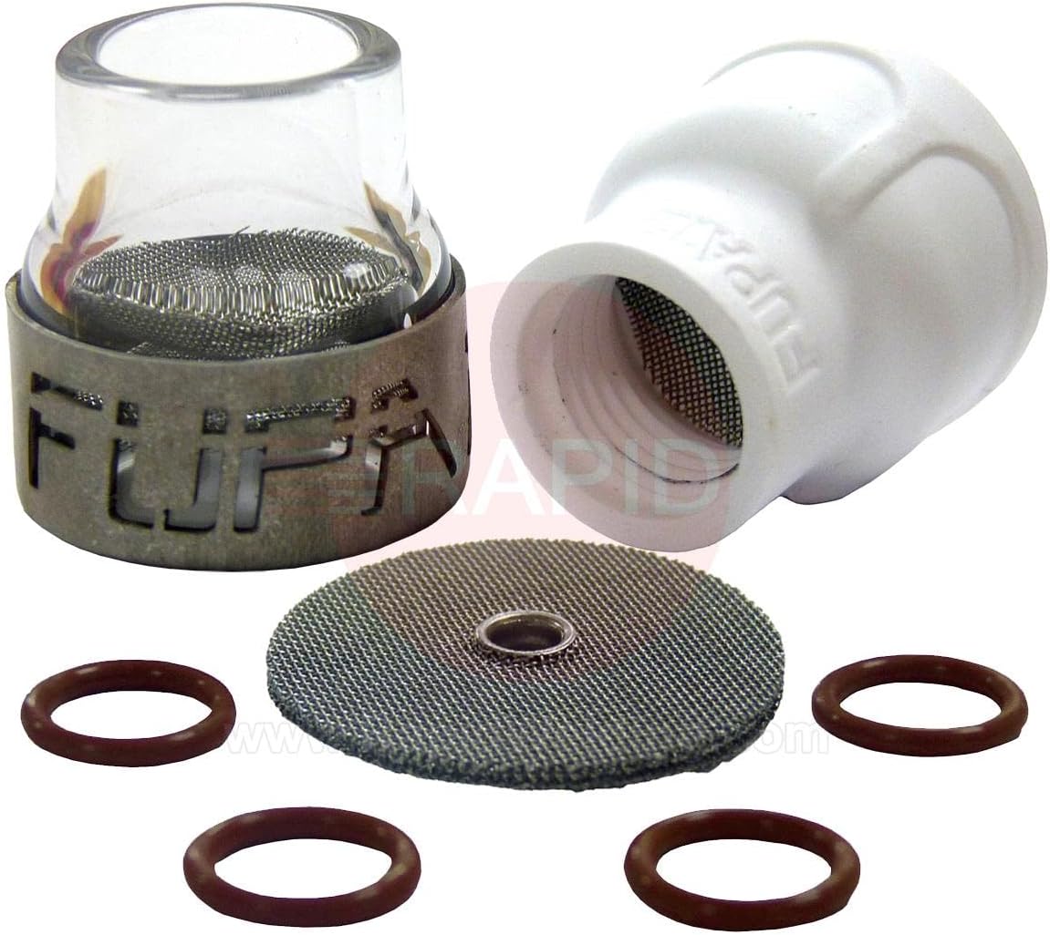
  • Furick Cup Dual FUPA #12 TIG Cup Kit (B09717HYGY): What It Is, When It Helps, and What to Compare

    Furick Cup Dual FUPA #12 TIG Cup Kit (B09717HYGY): What It Is, When It Helps, and What to Compare

    If youโ€™re running TIG and youโ€™re trying to improve coverage, visibility at the puddle, or consistency on longer beads, your cup setup matters more than most people think. A cup kit is not a magic fix, but it can reduce variablesโ€”especially when youโ€™re troubleshooting gas coverage problems that look like โ€œtungsten issuesโ€ or โ€œbad fillerโ€ but are actually shielding-related.

    This post covers one specific Amazon kit so you can verify what youโ€™re buying, compare it to alternatives, and avoid guessing on fitment.

    No products found.

    Product (verified)

    Amazon listing title: Furick Cup Dual FUPA #12 Welding Cup Kit w/Titanium Diffuser
    Verified ASIN: B09717HYGY
    Amazon URL used to confirm ASIN:https://www.amazon.com/Furick-Cup-Welding-Titanium-Diffuser/dp/B09717HYGY?tag=weldsupport-20

    What this is (plain-English)

    This is a TIG cup kit built around a #12 cup format with a diffuser component. In practice, cup/diffuser setups are used to shape and stabilize shielding gas flow at the nozzle, which can help when youโ€™re pushing cup size, stickout, or trying to keep coverage stable around corners and transitions.

    Unknown (Verify): exact torch series compatibility (WP-17/18/26 vs WP-9/20), included parts list, and whether any adapters are required. Confirm on the listing and/or manufacturer documentation before buying.

    Who this is for

    • TIG welders who are actively troubleshooting coverage/oxidation issues and want to eliminate โ€œcup setupโ€ as a variable.
    • Shops that standardize torch consumables and want a known kit instead of mixing random cups/diffusers.
    • Anyone doing cosmetic stainless work where coverage consistency is obvious in the finish.

    When itโ€™s not the right fix

    If your issue is actually gas supply, leaks, contaminated tungsten, or poor prep, a new cup kit wonโ€™t solve it. Treat this as a consumable/torch-end choice, not a process substitute.

    Performance & Use

    Cup setups affect how forgiving your shielding is. The right setup can make your results more repeatable; the wrong setup can make it harder to see whatโ€™s actually going wrong.

    What to compare before you buy

    • Torch series fitment: confirm your torch (WP-17/18/26, WP-9/20, etc.) and whether adapters are required (Unknownโ€”Verify).
    • Cup size vs access: larger cups can help coverage but can block access in tight joints.
    • Diffuser style: verify whatโ€™s included and how itโ€™s intended to be used (Unknownโ€”Verify).
    • Consumable availability: can you easily replace cups/diffusers without buying the whole kit again?
    • Your typical stickout and joint type: long stickout and tight corners punish marginal shielding setups.

    Comparable Amazon picks (optional)

    (Verified ASINs; plain affiliate links only.)

    Setup checklist (quick)

    • Confirm torch model/series and consumable family before ordering (do not assume).
    • Inspect for leaks at torch head, back cap, and fittings before blaming the cup.
    • If you change cup/diffuser setup, change one variable at a time and document results.

    Safety note

    Shielding gas displaces oxygen. Use ventilation appropriate for the space, and do not treat โ€œno visible smokeโ€ as โ€œsafe air.โ€ If youโ€™re welding stainless or anything with coatings, fume control matters.

  • Try Amazon Prime Free