Tag: MIG welding

  • Lincoln Electric SuperArc LA-90 MIG Wire ER80S-D2/ER90S-D2, 0.045″, 500 lb Drum (ED001378): Product Breakdown

    Lincoln Electric SuperArc LA-90 MIG Wire ER80S-D2/ER90S-D2, 0.045″, 500 lb Drum (ED001378): Product Breakdown

    Product not found.
    “>Lincoln Electric SuperArc LA-90 MIG Wire ER80S-D2/ER90S-D2, 0.045", 500 lb Drum (ED001378)

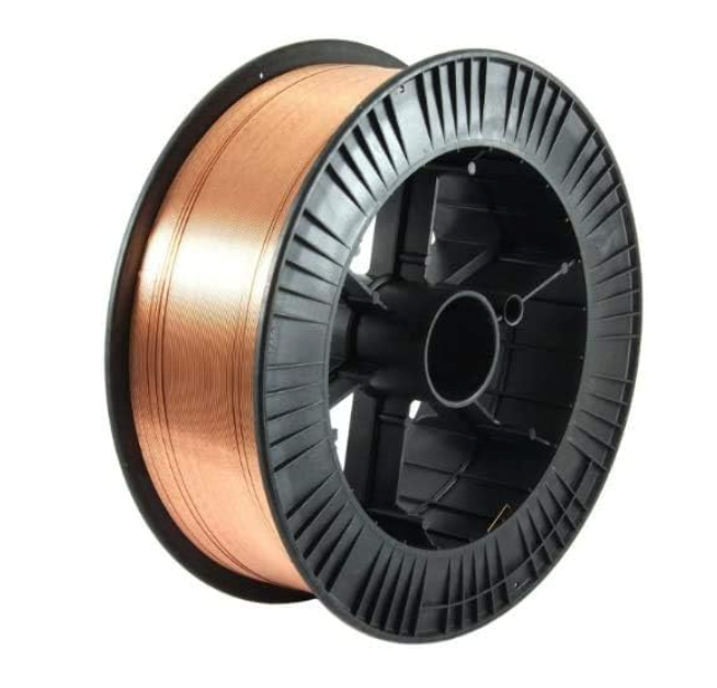
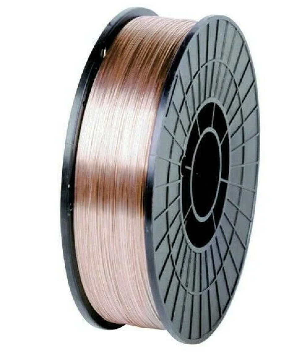
    Lincoln Electric SuperArc LA-90 MIG Wire ER80S-D2/ER90S-D2, 0.045″, 500 lb Drum (ED001378) is a low-alloy GMAW wire intended for higher-strength steel applications where the filler metal classification matters as much as the base metal and shielding gas. For buyers and weld support teams, the main point is simple: this is not a general-purpose wire. It is a classification-driven consumable that should be matched to the procedure, joint design, shielding gas, and deposit property requirements before release to production.

    Key Takeaways

    • Classification is the starting point: AWS A5.28 ER80S-D2 / ER90S-D2.
    • Wire diameter is 0.045 in, and the package is a 500 lb drum.
    • The listing identifies DC+ polarity and common shielding gas use, including 100% CO2 and argon/oxygen blends.
    • This product is aimed at higher-strength steel work, not general mild steel fill-in unless the procedure supports it.
    • Procedure approval, joint prep, and base metal verification still control the final answer. Unknown (Verify) when uncertain.

    What to Verify Before You Buy

    For maintenance buyers, the first filter is whether the wire classification matches the job. Check the WPS, base metal spec, and required deposited mechanical properties. ER80S-D2 and ER90S-D2 are not interchangeable by assumption. If your procedure calls for one range, confirm that the wire classification on the spool label and certification paperwork matches that requirement.

    Inspect: the wire package size, feed system capability, and storage space for a 500 lb drum. Large drums are efficient for high-volume work, but they create handling and feed-path requirements that smaller spools do not.

    Verify: drive roll setup, liner condition, inlet guide size, gun routing, and whether your feeder is configured for drum use. Unknown (Verify) if your feeder, drum adapter, or wire delivery kit is suitable for this package size.

    Support Check: Feedability and Setup

    Low-alloy solid wire performance is often limited by setup errors, not the wire itself. If the arc is unstable or feed speed is inconsistent, start with the wire path.

    • Check drive roll groove size against 0.045 in wire.
    • Inspect the liner for wear, contamination, or improper length.
    • Verify contact tip condition and bore size.
    • Check spool or drum brake tension so wire does not overrun or drag.
    • Inspect the inlet guide, gun cable bends, and any pinch points.

    If you need a more detailed feed system reference, use this internal guide: Lincoln Drive Roll Pressure Adjustment Guide. It covers wire feed slip, burnback, birdnesting, and wire shaving fixes.

    Shielding Gas and Polarity

    The product description identifies DC+ polarity and common use with 100% CO2 and argon/oxygen blends. That helps narrow selection, but it does not replace a procedure. Gas choice affects arc characteristics, spatter level, penetration profile, and bead shape. The exact procedure may require a specific blend, flow rate, or torch setup. Unknown (Verify) unless your WPS or governing document specifies it.

    Check: regulator condition, flow meter accuracy, hose integrity, and gas delivery at the gun. A wire can be correct and still perform poorly if shielding is inconsistent.

    Verify: polarity at the machine before loading the wire into production. Reversed polarity can create immediate performance problems and misleading troubleshooting.

    WSP Lookup and Filler Metal Selection

    If you are building a purchasing or support decision, use the available selection tools as starting points only. They help narrow the search, but they do not guarantee procedure approval.

    Use any filler metal finder output as a selection starting point, not as a substitute for your WPS, base metal qualification, or code requirement.

    Product and Parts Notes

    The allowed product for this draft is the ArcWeld listing for Lincoln Electric SuperArc LA-90 MIG Wire ER80S-D2/ER90S-D2, 0.045″, 500 lb Drum (ED001378). Use the ArcWeld product page when you need the vendor-facing product record and ordering reference.

    Product not found.

    “>View the ArcWeld product page

    The product shortcode provided for internal use is:

    Lincoln Electric SuperArc LA-90 MIG Wire ER80S-D2/ER90S-D2, 0.045", 500 lb Drum (ED001378)

    Lincoln Electric SuperArc LA-90 MIG Wire ER80S-D2/ER90S-D2, 0.045", 500 lb Drum (ED001378)

    SuperArc® LA-90™ is a premium, copper-coated low-alloy MIG (GMAW) wire from Lincoln Electric designed to meet 80,000–90,000 psi tensile strength requirements for higher-strength steel applications. Classified to AWS A5.28 ER80S-D2 / ER90S-D2, LA-90 delivers strong, consistent as-welded mechanical performance across common shielding gas mixes, including 100% CO₂ and argon/oxygen blends, with DC+ polarity. This list...

    View at Arc Weld Store

    Do not assume additional compatibility, certifications, or performance values beyond what is stated in the product record. Unknown (Verify) if a specific feeder, gun, or procedure package is not documented.

    Practical Troubleshooting Sequence

    1. Check the wire classification on the label against the WPS.
    2. Inspect the feed path from drum to contact tip.
    3. Verify polarity, gas type, and gas flow.
    4. Check the contact tip for wear or mismatch.
    5. Inspect the joint prep, mill scale, rust, oil, and moisture.
    6. Verify whether the issue follows the wire or stays with the machine setup.

    If the deposit profile is not meeting expectations, do not jump straight to a different wire class. First confirm that the setup matches the intended procedure. Many apparent filler metal problems are actually feed issues, shielding issues, or base metal prep issues.

    Safety Notes

    • Follow the applicable WPS, SDS, and site hot-work controls.
    • Handle the 500 lb drum with proper lifting equipment. Do not manually lift or reposition it without a safe method.
    • Keep hands clear of feed rollers and pinch points during setup.
    • Use eye, hand, and respiratory protection as required by the job and local exposure controls.
    • Confirm ventilation and fume control before welding on production parts.

    FAQ

    Is this wire for general mild steel welding?
    Not by default. It is classified as ER80S-D2 / ER90S-D2 and should be matched to the procedure and strength requirements. Unknown (Verify) for any mild steel application unless the WPS allows it.

    What polarity is listed for this wire?
    The product description identifies DC+ polarity.

    Can I use it with any shielding gas?
    No. The listing mentions common use with 100% CO2 and argon/oxygen blends, but the actual approved gas depends on your procedure. Treat gas references as a starting point only.

    What should I check first if feed is unstable?
    Check drive roll pressure, liner condition, contact tip wear, cable routing, and drum brake tension before replacing the wire.

    Sources Checked

    • ArcWeld product record: Lincoln Electric SuperArc LA-90 MIG Wire ER80S-D2/ER90S-D2, 0.045″, 500 lb Drum (ED001378)
    • Provided internal product reference shortcode
    • Provided internal links: drive roll pressure adjustment guide and related welding support articles

    Related Weld Support Guides

  • S19418-1 Lincoln Style Gas Diffuser Pack of 2 – Arc Weld by Masterweld: Product Breakdown

    S19418-1 Lincoln Style Gas Diffuser Pack of 2 – Arc Weld by Masterweld: Product Breakdown

    Product not found.
    “>S19418-1 Lincoln Style Gas Diffuser Pack of 2 - Arc Weld by Masterweld

    The S19418-1 Lincoln Style Gas Diffuser Pack of 2 – Arc Weld by Masterweld is a replacement support part for a specific Lincoln Style gun configuration. Based on the product description provided, it is intended for the Magnum 250L Classic Series Gun and does not work with PRO series guns. That is the first fitment check any buyer should confirm before ordering or installing the part.

    For welders, maintenance buyers, and support teams, the practical question is not just “what is it?” but “will it fit my gun, and will it restore stable shielding gas flow at the diffuser end?” The answer depends on the gun model, consumable setup, and correct installation. Unknown (Verify) for any detail not stated in the source product description.

    Key Takeaways

    What a Gas Diffuser Does

    A gas diffuser is a consumable support component at the front end of a MIG gun. Its job is to help route shielding gas into the weld zone and support the front-end consumable stack. When a diffuser is worn, damaged, blocked, or mismatched to the gun, the result can be poor gas coverage, unstable arc behavior, spatter issues, or inconsistent contact tip performance.

    This part should be treated as a fitment-controlled component. In MIG welding, “Lincoln Style” does not automatically mean universal compatibility across every Lincoln-branded or Lincoln-style gun. Verify the exact gun series and front-end consumables before purchase.

    Before You Buy: Verify Fitment

    Use the following checks before placing the order:

    If the gun serial number, front-end configuration, or service history is unclear, do not assume interchangeability. A wrong diffuser can create repeat service calls and wasted consumables.

    Installation and Service Checks

    Before replacing the diffuser, follow basic service discipline:

    After installation, test the gun in a controlled setting. Verify arc start, gas coverage, and front-end retention. If the arc remains erratic or shielding is still poor, inspect the full consumable stack instead of assuming the diffuser is defective.

    Troubleshooting Support: What to Check

    If a front-end issue continues after replacement, work through the following steps:

    If the symptoms persist, document the gun model, part numbers, and observed failure mode before requesting support. That makes it easier to confirm whether the diffuser is the correct replacement or whether another front-end component is the real cause.

    Product / Parts Notes

    This listing is for the S19418-1 Lincoln Style Gas Diffuser Pack of 2 – Arc Weld by Masterweld. The product description supplied states only the following actionable fitment point: it is for a Magnum 250L Classic Series Gun and does not work with PRO series guns. Any additional compatibility claims would be Unknown (Verify).

    Buyers should not infer cross-compatibility from the phrase “Lincoln Style” alone. That term is useful as a starting point, not as final proof of fitment. Match the actual front-end architecture of the gun before stocking the part for maintenance use.

    Related Technical Reference

    For a broader view of MIG support materials and how consumable selection affects welding setup, see this related article: Aluminum ER 5554 3/64″ X 5lb. MIG Welding Wire Spool By Washington Alloy – Weld Support Parts Blog.

    Safety Notes

    FAQ

    Q: What gun does this diffuser fit?
    A: The provided source description says it is for a Magnum 250L Classic Series Gun. Exact fitment beyond that is Unknown (Verify).

    Q: Will it work with PRO series guns?
    A: No. The source description explicitly says it does not work with PRO series guns.

    Q: Is this a full consumable kit?
    A: No. This is identified as a gas diffuser pack of 2. Any included accessory detail beyond that is Unknown (Verify).

    Q: What should I inspect if the weld still has shielding problems after replacement?
    A: Check the nozzle, contact tip, liner, gas hose, fittings, and gas supply before assuming the diffuser is the only issue.

    Sources Checked

    “>S19418-1 Lincoln Style Gas Diffuser Pack of 2 – Arc Weld by Masterweld
  • Internal reference: Aluminum ER 5554 3/64″ X 5lb. MIG Welding Wire Spool By Washington Alloy – Weld Support Parts Blog
  • Bottom line: this part is a straightforward front-end replacement, but its value depends on correct fitment. Confirm the gun series, verify that the gun is not a PRO series model, and inspect the entire front-end assembly during service. That is the practical way to avoid downtime and repeat failures.

    Related Arc Weld Part

    S19418-1 Lincoln Style Gas Diffuser Pack of 2 - Arc Weld by Masterweld

    S19418-1 Lincoln Style Gas Diffuser Pack of 2 – Arc Weld by Masterweld

    Lincoln Style gas diffuser for Magnum 250L Classic Series Gun – Does not work with PRO series guns

    View at Arc Weld Store

    Related Weld Support Guides

  • When Welding Consumables Should Be Replaced

    Product not found.
    ™-black-clearlight-4x-auto-darkening-welding-helmet-for-men-with-light-state-and-4-arc-sensors-welding-mask-with-13-4-sq-in-viewing-area-lightweight-welding-hood?utm_source=blog&utm_medium=internal&utm_campaign=when-welding-consumables-should-be-replaced”>Miller Digital Infinity™ Black, ClearLight 4X - Auto Darkening Welding Helmet for Men with Light State and 4 Arc Sensors - Welding Mask with 13.4 sq. in. Viewing Area - Lightweight Welding Hood

    Welding consumable replacement is part of normal maintenance, not an emergency task. Consumables wear out from heat, spatter, arc exposure, and mechanical handling. The right replacement interval depends on process, amperage, duty cycle, base material, and operator technique.

    Key Takeaways

    When to Replace Welding Consumables

    Replace a consumable when it no longer supports consistent weld quality or safe operation. Common signs include:

    Process-by-Process Replacement Guidance

    MIG / GMAW

    Common wear parts include contact tips, nozzles, diffusers, liners, drive rolls, and gun neck consumables. Replace them when wire feeding becomes inconsistent, the arc becomes unstable, or the tip bore is enlarged, ovaled, or burned. If the wire sticks, shaves, or birdnests repeatedly, inspect the liner and drive system before assuming the torch is at fault.

    TIG / GTAW

    Replace tungsten electrodes when the tip is contaminated, cracked, severely balled outside the intended process, or no longer grinds to a clean point or taper. Gas cups, collets, collet bodies, back caps, and torch bodies should be replaced if they are cracked, warped, or no longer hold components securely. If shielding is poor, check for leaks, loose parts, or damaged insulators.

    Stick / SMAW

    Stick electrodes are consumables by design and are used once. Replace unused electrodes if flux is damaged, damp, cracked, or contaminated. For electrode holders and cable connections, replace worn jaws, burned insulation, or damaged lugs if they affect current transfer or safety.

    Plasma Cutting

    Replace electrodes, nozzles, shields, swirl rings, and retaining caps when cut quality drops or the parts show erosion, double arcing, enlarged orifices, or heat damage. Plasma consumables are often replaced as a set when the wear pattern affects arc shape or kerf consistency.

    Troubleshooting Before Replacement

    If the weld or cut quality changes, verify these items before ordering parts:

    If the issue remains after these checks, the consumable is likely worn or damaged.

    Replacement Triggers by Condition

    Product / Parts Section

    For operators who need a clearer view of the arc and puddle during inspection or setup, the following product is available in the Weld Support Parts catalog:

    Product details not listed above are Unknown (Verify). Verify fit, process coverage, lens requirements, and compliance before purchase.

    Safety Notes

    FAQ

    How often should welding consumables be replaced?

    There is no universal interval. Replace them when wear affects quality, feedability, shielding, or safety. Frequency depends on process and workload.

    Should consumables be replaced as a set?

    Sometimes. Plasma consumables are often changed together when wear is advanced. MIG and TIG parts may be replaced individually if only one component is worn.

    Can I keep using a worn contact tip or nozzle?

    Not if it affects arc performance or gas coverage. Small wear can quickly become a defect or a shutdown.

    What is the first part to check when weld quality changes?

    Check the consumable, then verify gas, settings, workpiece prep, and cable condition.

    Sources Checked

    Related Weld Support Guides

  • MIG Nozzle and Diffuser Replacement Guide

    Bernard NT-3800C Centerfire Welding Nozzle - Tapered MiniFlush 3/8" for Large Diffuser
    “>Bernard NT-3800C Centerfire Welding Nozzle - Tapered MiniFlush 3/8" for Large Diffuser

    Front-end MIG gun parts wear out in service. A worn nozzle or diffuser can cause poor gas coverage, inconsistent wire feeding, excess spatter, and unstable arc starts. This guide covers when to replace these parts, what to inspect, and how to troubleshoot common front-end problems.

    Key Takeaways

    When to Replace a MIG Nozzle

    The nozzle directs shielding gas around the weld zone and helps protect the contact tip and diffuser. Replace it when you see any of the following:

    If the nozzle is still structurally sound, cleaning may extend service life. If it has lost shape or fit, replace it.

    When to Replace a Diffuser

    The diffuser routes gas to the nozzle and supports the contact tip. Replace it if you find:

    A damaged diffuser can look like a nozzle problem. If cleaning the nozzle does not restore performance, inspect the diffuser closely.

    Troubleshooting Front-End MIG Problems

    1. Excess spatter at the nozzle

    Possible causes:

    Start by checking gas flow, contact tip condition, and nozzle cleanliness before replacing more parts.

    2. Arc instability or erratic starts

    Possible causes:

    If the front end looks good, move upstream to the liner and drive system.

    3. Poor shielding gas coverage

    Possible causes:

    Confirm gas flow at the source and inspect the gun body before assuming the nozzle is the only problem.

    4. Frequent burnback

    Possible causes:

    Burnback can damage the diffuser and tip seat. Replace damaged parts before returning the gun to service.

    Replacement Checklist

    Product and Parts Note

    If you need a replacement nozzle for a large centerfire diffuser, the ArcWeld-listed option is below.

    Bernard NT-3800C Centerfire Welding Nozzle - Tapered MiniFlush 3/8" for Large Diffuser

    Bernard NT-3800C Centerfire Welding Nozzle – Tapered MiniFlush 3/8" for Large Diffuser

    Enhance your welding performance with the Bernard NT-3800C Centerfire Nozzle. Specifically designed as a tapered, MiniFlush accessory for large centerfire diffusers, this nozzle ensures precision and efficiency in every weld. The Bernard NT-3800C is your go-to centerfire welding nozzle, featuring a built-in spatter shield. This essential design element minimizes spatter, promoting a cleaner workspace and reducing…

    View at Arc Weld Store

    Product noted: Bernard NT-3800C Centerfire Welding Nozzle – Tapered MiniFlush 3/8″ for Large Diffuser

    Use case: Large centerfire diffuser front-end nozzle replacement. Compatibility details beyond the product title are Unknown (Verify).

    Safety Notes

    FAQ

    How often should I replace a MIG nozzle?

    There is no fixed interval. Replace it when spatter, damage, or poor fit affects gas coverage or weld quality.

    How do I know if the diffuser is bad?

    Look for stripped threads, burn damage, cracks, gas leaks, or a nozzle that will not seat correctly.

    Can I keep cleaning a nozzle instead of replacing it?

    Yes, if the nozzle is still round, undamaged, and maintains proper fit. Replace it when cleaning no longer restores function.

    What else should I check if replacement parts do not fix the issue?

    Check the contact tip, liner, drive rolls, gas supply, and torch setup. Front-end wear is only one possible cause.

    Sources Checked

    Note: Exact compatibility, dimensions, and application limits for the listed nozzle are Unknown (Verify) unless confirmed by the equipment manufacturer or the product detail page.

    Related Weld Support Guides

  • Why Does My MIG Contact Tip Keep Burning Back?

    Tweco VTS30 Velocity Light Duty MIG Welding Contact Tip, 0.030" Wire Size, Standard (Pack of 10)
    “>Tweco VTS30 Velocity Light Duty MIG Welding Contact Tip, 0.030" Wire Size, Standard (Pack of 10)

    If your MIG contact tip keeps burning back, the problem is usually not just the tip. Burnback happens when the wire stops feeding normally while the arc stays on the wire end. The wire then melts back into the tip and can fuse to it.

    This guide covers the common causes that get missed after a tip replacement: wrong tip size, liner drag, spool brake setting, worn drive rolls, and stickout issues.

    Key Takeaways

    What Burnback Means

    In MIG welding, burnback means the wire burns back into the contact tip instead of feeding out at the normal rate. You may see the wire fused to the tip, a cratered wire end, or a tip that overheats quickly after starting the arc.

    1) Check the Contact Tip Size

    The tip bore has to match the wire size closely enough for stable electrical contact, but not so tight that it creates drag. A tip that is too small for the wire can increase friction and heat. A worn or damaged tip can also cause erratic contact and feeding problems.

    Verify the wire diameter and the tip marking before replacing more parts. If the wire size and tip size do not match, correct that first.

    2) Check for Liner Drag

    A liner that has contamination, sharp bends, wear, or the wrong length can make the wire feed unevenly. When wire speed drops even briefly, burnback can happen fast.

    Inspect the liner path for:

    If the wire feed feels rough when you jog it, suspect liner drag before blaming the tip.

    3) Check Drive Rolls

    Worn, mismatched, or improperly tensioned drive rolls can slip or flatten the wire. That creates inconsistent feed speed and can lead to burnback at the tip.

    Inspect the drive rolls for:

    If the wire feed is unstable at the feeder, fix the drive roll setup before changing the tip again.

    4) Check Spool Brake Tension

    On spool-fed systems, brake tension that is too tight can overload the drive system. Brake tension that is too loose can let the spool overrun and create feed inconsistency. Either condition can contribute to burnback.

    Verify that the spool turns smoothly and stops without freewheeling. If you hear the feeder laboring or see wire birdnesting risk, the spool brake may need adjustment. Exact brake settings are machine-specific and Unknown (Verify).

    5) Check Stickout

    Stickout is the distance from the contact tip to the work before the arc starts. Too much stickout changes electrical behavior and can make the wire heat up differently. That can increase burnback risk, especially on thin wire or with marginal feed.

    Keep stickout within the procedure used for the job. If the operator has been holding the gun too far from the work, shorten it and test again.

    6) Check Gun Angle and Travel Technique

    Steep angles, excessive arc length, or poor gun positioning can make the wire stick or burn back more easily. A stable push angle and consistent travel help keep the arc and wire feed predictable.

    If burnback happens only with one operator, review technique before replacing parts.

    7) Check Heat and Parameter Balance

    Burnback can also happen when the arc is too hot for the wire feed speed, or when the wire feed is too slow for the voltage and current being used. If the arc stays on too long after the trigger is released, postflow and wire retraction behavior may also matter. Machine settings are Unknown (Verify) without the unit model.

    If the machine is set for a small wire but the feed path is restricted, the result can look like a tip problem even when it is a system problem.

    Support Check Sequence

    1. Confirm wire size and contact tip size match.
    2. Inspect the tip for wear, spatter, and overheating.
    3. Test wire feed by jogging wire with the tip removed.
    4. Check liner drag and cable routing.
    5. Inspect drive rolls and tension.
    6. Verify spool brake tension on spool-fed systems.
    7. Review stickout, gun angle, and welding settings.

    When to Replace the Tip

    Replace the contact tip if it is visibly enlarged, burned, fused, or no longer feeds wire smoothly. If tips keep failing right after replacement, stop changing tips and find the feed restriction first.

    Product / Parts

    For a replacement tip option in 0.030″ wire size, see the following ArcWeld product:

    Verify wire size, gun compatibility, and nozzle family before ordering. Compatibility details beyond the provided product data are Unknown (Verify).

    Safety Notes

    FAQ

    Why does my tip burn back right after I replace it?

    Usually because the underlying feed issue was not fixed. Check tip size, liner drag, drive rolls, spool brake, and stickout.

    Can a wrong contact tip size cause burnback?

    Yes. A tip that is too small, worn, or damaged can increase drag and heat, which can contribute to burnback.

    Can drive rolls cause a contact tip to burn back?

    Yes. Slipping or worn drive rolls can slow wire feed enough to cause burnback.

    Is burnback always caused by too much heat?

    No. Heat is part of it, but unstable wire feed is a common root cause.

    Sources Checked

    Related Weld Support Guides

  • Troubleshooting Weld Quality Before Replacing Parts

    Tweco MSAK-354 Control Wire Assembly for MIG Guns - High Quality Welding Parts
    “>Tweco MSAK-354 Control Wire Assembly for MIG Guns - High Quality Welding Parts

    If weld quality drops, do not start by replacing parts. Most issues come from process settings, consumables, shielding gas, ground connection, wire feed, or operator technique. Use this weld quality troubleshooting guide to isolate the cause before you spend time and money on parts.

    Key Takeaways

    Start With the Welding Process

    Many weld defects are process related, not part failures. Verify the following before opening the gun or feeder.

    Check Shielding Gas First

    Shielding gas problems can look like bad consumables or a failing gun. Verify gas setup before replacing parts.

    Inspect the Wire Feed System

    Wire feed instability can create arc fluctuation, burnback, and inconsistent bead shape.

    Review Consumables and Contact Surfaces

    Before replacing a control wire assembly or gun component, inspect the basic wear items first.

    Check the Base Metal and Joint Prep

    Weld quality problems often start at the joint.

    Common Symptoms and What to Check

    When a Part Replacement Makes Sense

    Replace parts only after the problem follows the component or shows clear wear. For MIG gun control and feed-related issues, the Tweco MSAK-354 Control Wire Assembly for MIG Guns may be a relevant replacement option when the original assembly is damaged or no longer performing as expected. Use the part only if it matches the existing setup. Compatibility is Unknown (Verify).

    Tweco MSAK-354 Control Wire Assembly for MIG Guns - High Quality Welding Parts

    Tweco MSAK-354 Control Wire Assembly for MIG Guns – High Quality Welding Parts

    Introducing the MSAK-354 Control Wire Assembly, a premium component designed to enhance your MIG welding experience. This high-quality control wire assembly is manufactured by Tweco, a reputable name in the welding industry. Precision-engineered, the MSAK-354 provides reliable performance and durability that meets the demands of both professional welders and DIY enthusiasts. The MSAK-354 is essential for ensuring…

    View at Arc Weld Store

    Do not assume the control wire assembly is the cause of poor weld quality until you have checked process settings, gas coverage, wire feed, and consumables.

    Support Workflow for Maintenance Teams

    1. Document the defect type: porosity, spatter, lack of fusion, undercut, burnback, or instability.
    2. Verify machine settings against the procedure or WPS.
    3. Inspect gas, wire feed, liner, tip, nozzle, and work clamp.
    4. Clean the joint and verify fit-up.
    5. Run a test weld after each change so you know what corrected the issue.
    6. Replace parts only after the fault is isolated.

    Safety Notes

    FAQ

    Why does the weld look bad if the machine seems fine?
    Weld appearance can be affected by shielding gas, contamination, wire feed instability, joint prep, or technique. A machine can operate normally while the process is still out of control.

    Should I replace the gun first?
    No. Check the consumables, wire path, work clamp, gas delivery, and settings first. Replace the gun or its components only after you isolate the fault.

    Can a bad ground cause porosity?
    Yes. A poor work connection can contribute to unstable arc behavior and poor bead quality.

    What is the fastest way to narrow it down?
    Make one change at a time and run a short test weld. That is the most reliable way to separate process issues from hardware issues.

    Sources Checked

  • MIG Weld Spatter Too High

    Washington Alloy 309 MIG Welding Wire, 2 LB Spool, .030" Stainless Steel for High Temp Welding
    “>Washington Alloy 309 MIG Welding Wire, 2 LB Spool, .030" Stainless Steel for High Temp Welding

    If MIG weld spatter is running high, start with the basics: voltage, wire feed speed, shielding gas, stickout, and gun angle. Spatter is usually a setup issue, a consumable issue, or both. Do not chase one setting without checking the full weld setup.

    Key Takeaways

    Troubleshooting Steps

    1. Check voltage and wire feed speed

    If voltage is too low for the wire feed speed, the wire can stub into the puddle and throw spatter. If wire feed is too high for the voltage, the arc can become harsh and unstable. Make small changes and test one variable at a time.

    2. Verify shielding gas coverage

    Poor shielding gas coverage increases spatter and can cause porosity. Check the flow, hose condition, fittings, and nozzle buildup. Clean the nozzle if spatter is restricting gas flow.

    3. Inspect stickout and work angle

    Long stickout reduces arc stability and can drive spatter up. Excessive push or drag angle can also disturb shielding and puddle control. Hold the gun angle consistent and keep stickout controlled.

    4. Check wire condition and feeding

    Dirty, rusty, kinked, or poorly driven wire can feed unevenly and create spatter. Inspect the spool, drive rolls, and liner. If feed is surging, the arc will usually show it.

    5. Check joint prep and base metal condition

    Mill scale, rust, oil, paint, and moisture all increase spatter. Poor fit-up can also make the arc unstable. Clean the joint and verify the gap, root face, and edge condition before welding.

    Common Causes of MIG Weld Spatter

    Product and Parts Check

    When spatter remains high after setup checks, verify consumables and wire selection for the job. If you are welding stainless or high-temperature service material, the wire choice must match the application and procedure. Unknown (Verify) if your procedure allows the following wire for the joint and material.

    Allowed product: Washington Alloy 309 MIG Welding Wire, 2 LB Spool, .030″ Stainless Steel for High Temp Welding
    ArcWeld shortcode:

    Washington Alloy 309 MIG Welding Wire, 2 LB Spool, .030" Stainless Steel for High Temp Welding

    Washington Alloy 309 MIG Welding Wire, 2 LB Spool, .030" Stainless Steel for High Temp Welding

    Experience superior welding performance with Washington Alloy 2 Lb. Spool Mig Welding Wire 309 Stainless Steel (.030 X 2 LB.). This high-quality 309 mig welding wire is engineered for exceptional strength and durability in a variety of welding projects. The USA 309 wire is specifically designed for welding heat-resistant AISI 309 and other chromium grades of stainless steel. It excels in applications where pre-hea...

    View at Arc Weld Store

    This product may be relevant when the job calls for 309 stainless wire. Verify base metal, joint design, shielding gas, polarity, and procedure before use.

    Safety Notes

    FAQ

    Why does MIG weld spatter increase suddenly?

    Common causes are a change in voltage, wire feed, gas flow, stickout, dirty consumables, or contaminated material. Check the full setup before changing the machine again.

    Can gas flow alone fix spatter?

    No. Gas flow is one factor. High spatter can still come from poor voltage-to-wire-feed balance, bad angle, long stickout, or worn tips.

    Does contact tip wear cause spatter?

    Yes. A worn or oversized contact tip can create unstable wire delivery and a rough arc.

    Should I change wire before changing settings?

    Only if the wire is damaged, rusty, or feeding poorly. Otherwise, verify machine settings and shielding gas first.

    Sources Checked

    Related Weld Support Guides

  • MIG Porosity Causes and Fixes

    Washington Alloy E71T-GS .045 Gasless MIG Welding Wire 11 LB Spool for Easy Welding Tasks
    “>Washington Alloy E71T-GS .045 Gasless MIG Welding Wire 11 LB Spool for Easy Welding Tasks

    MIG porosity is gas trapped in the weld metal as it solidifies. It usually shows up as pinholes, worm tracks, or a rough weld surface. The main causes are shielding gas problems, contamination, incorrect gun setup, and poor technique.

    Key Takeaways

    Common MIG Porosity Causes

    1. Shielding gas contamination or loss

    If shielding gas is not reaching the arc, air will mix into the weld pool. That creates porosity. Common reasons include an empty cylinder, a closed valve, a leaking hose, loose fittings, or a damaged gun neck.

    2. Excessive stickout

    Stickout that is too long reduces shielding effectiveness and can make the arc unstable. Long stickout also increases electrical resistance and can change the way the wire melts.

    3. Dirty base metal

    Rust, oil, mill scale, paint, galvanizing residue, moisture, and cutting fluids can all cause porosity. Contamination vaporizes in the arc and gets trapped in the weld.

    4. Moisture on the work or wire

    Condensation, wet storage, or damp wire can introduce hydrogen and other gases into the weld. This can create visible porosity or internal defects.

    5. Incorrect torch angle or excessive travel speed

    Too much angle or moving too fast can pull shielding gas away from the puddle. That leaves the weld exposed to the atmosphere.

    6. Nozzle blockage or spatter buildup

    Spatter, soot, and debris in the nozzle can disrupt gas coverage. A restricted nozzle can cause erratic shielding even when gas flow looks normal at the regulator.

    7. Drafts and air movement

    Fans, open doors, shop airflow, and outdoor wind can blow shielding gas away from the weld zone. Gasless flux-cored wire can reduce this issue, but it does not solve contamination on the workpiece.

    Troubleshooting Steps

    Step 1: Inspect the weld defect

    Look at the porosity pattern. Scattered pinholes often point to contamination or gas disturbance. Linear porosity can point to travel issues, nozzle problems, or gas coverage loss along the weld path.

    Step 2: Check shielding gas delivery

    Verify the cylinder is open, the regulator is set correctly, and the flowmeter is working. Inspect hoses, fittings, and the gun for leaks. Unknown (Verify): specific recommended flow rate depends on wire type, joint position, and shielding gas mix.

    Step 3: Clean the nozzle and contact tip area

    Remove spatter and buildup from the nozzle, diffuser, and tip. Make sure gas ports are not blocked. Replace worn parts if cleaning does not restore a clear gas path.

    Step 4: Shorten stickout if needed

    Keep wire stickout within the range recommended for your process and consumable. If porosity appears after a setup change, reduce stickout and re-test.

    Step 5: Clean the joint and surrounding area

    Remove oil, rust, paint, moisture, and heavy scale before welding. Clean beyond the weld zone so contamination does not get pulled into the arc.

    Step 6: Reduce drafts

    If possible, block crossflow from fans or doors. For field work, reposition the setup or use wind protection that does not disturb the arc.

    Step 7: Review travel technique

    Use steady travel speed and maintain a consistent torch angle. Avoid weaving so wide that the shielding gas cannot cover the full puddle.

    Support Parts and Consumables

    If you need a wire option for gasless MIG work, this product may be relevant for certain applications:

    Washington Alloy E71T-GS .045 Gasless MIG Welding Wire 11 LB Spool for Easy Welding Tasks. Verify suitability for your material, thickness, polarity, and procedure before use.

    Safety Notes

    FAQ

    What is the most common cause of MIG porosity?

    Shielding gas loss or contamination is the most common cause. Start with gas delivery, nozzle condition, and airflow around the weld.

    Can dirty steel cause porosity?

    Yes. Rust, oil, paint, moisture, and mill scale can all create gas pockets in the weld.

    Does long stickout cause porosity?

    Yes. Excessive stickout can reduce shielding gas effectiveness and destabilize the arc.

    Will gasless wire fix porosity?

    Not automatically. Gasless wire can help when wind makes gas shielding difficult, but dirty material, poor technique, and moisture can still cause defects.

    Sources Checked

    Related Weld Support Guides

  • How to Stop MIG Nozzle Spatter from Blocking Gas Coverage

    MIG weld porosity is often blamed on shielding gas settings, but a blocked nozzle can cause the same problem. When spatter builds up inside the MIG gun nozzle, shielding gas flow can become restricted, uneven, or turbulent. The result may be pinholes, black soot, erratic arc behavior, and poor bead appearance.

    This guide explains how nozzle spatter buildup causes gas coverage problems, what to check first, and how to clean and prevent buildup without damaging the gun consumables.

    Key Takeaways

    • Spatter inside the MIG nozzle can restrict shielding gas and cause porosity.
    • A nozzle that looks acceptable from the outside may be blocked internally.
    • Nozzle gel can reduce spatter adhesion, but it should not be over-applied.
    • Contact tip, diffuser, and nozzle condition should be checked together.
    • Porosity troubleshooting should include gas leaks, flow rate, wind, base metal cleanliness, and consumable buildup.

    Problem / Context

    A MIG nozzle collects spatter during normal welding. If the buildup is not removed, it can narrow the gas path around the contact tip and diffuser. Shielding gas may still be flowing at the regulator, but the gas envelope at the weld puddle may be weak or uneven.

    This issue is common when welding with short-circuit transfer, welding in tight corners, using excessive wire stickout, welding on dirty material, or running settings that create heavy spatter. It can also happen when the nozzle is dipped too deeply into anti-spatter compound.

    Root Causes

    • Internal nozzle buildup: Spatter collects inside the nozzle and blocks the gas path.
    • Dirty diffuser: Spatter or debris around diffuser holes disrupts gas flow.
    • Damaged contact tip: A worn or oversized tip can cause unstable wire feeding and more spatter.
    • Excessive nozzle gel: Too much compound can contaminate the nozzle, contact tip, or weld area.
    • Incorrect settings: Voltage, wire speed, stickout, and travel angle can all affect spatter level.
    • External gas problems: Wind, leaks, low cylinder pressure, incorrect gas mix, or poor flow rate can also cause porosity.

    Solution

    Remove the nozzle and inspect the inside, not just the outside edge. If spatter is narrowing the opening or covering diffuser holes, clean the nozzle before adjusting the machine. Use proper MIG pliers or a nozzle cleaning tool rather than striking the nozzle against the workbench.

    • Turn off the welder before removing or servicing gun consumables.
    • Remove the nozzle and clear spatter from the inside wall.
    • Inspect the contact tip for wear, burnback, keyholing, or blocked wire passage.
    • Check the diffuser or gas ports for spatter blockage.
    • Reinstall consumables securely without cross-threading.
    • Apply nozzle gel lightly if used, keeping it away from the contact tip bore and weld joint.
    • Run a short test weld and inspect for porosity before continuing production work.

    Specs / Verification Notes

    Item to VerifyWhat to CheckNotes
    MIG gun modelNozzle, tip, and diffuser compatibilityUnknown (Verify)
    Wire sizeContact tip size matches wire diameterUnknown (Verify)
    Shielding gasCorrect gas or gas mix for processUnknown (Verify)
    Gas flowFlow at the gun, not only at the regulatorUnknown (Verify)
    Nozzle conditionInternal spatter, deformation, loose fitReplace if damaged
    Diffuser conditionBlocked gas holes or damaged threadsReplace if damaged

    Product Section

    Nozzle gel can help reduce weld spatter adhesion inside a MIG nozzle. It should be used as a support item, not as a substitute for correct settings, clean consumables, and proper shielding gas coverage. Verify current product size, seller, and safety information before purchase.

    Last update on 2026-07-14 / Affiliate links / Images from Amazon Product Advertising API

    Comparison Table

    ApproachBest UseRisk
    Routine nozzle cleaningDaily MIG gun maintenanceMay be skipped when production is rushed
    Nozzle gelReducing spatter adhesionOver-application can create contamination risk
    Replacing nozzleDamaged, distorted, or heavily packed nozzleWrong nozzle can affect gas coverage
    Changing weld settingsReducing excessive spatter at the sourceIncorrect changes can create new weld defects

    Safety Notes

    • Allow the nozzle and contact tip to cool before handling. MIG gun front-end parts can remain hot after welding.
    • Use safety glasses when removing spatter because fragments can break loose during cleaning.
    • Follow the product SDS for nozzle gel or anti-spatter compound handling and storage.
    • Keep anti-spatter compounds away from open flames unless the product documentation confirms safe use conditions.
    • Follow OSHA welding, cutting, and brazing requirements and ANSI Z49.1 safety guidance for welding, cutting, and allied processes.

    FAQ

    Can nozzle spatter cause MIG porosity?

    Yes. Heavy spatter buildup inside the nozzle can interfere with shielding gas coverage and contribute to porosity.

    How often should a MIG nozzle be cleaned?

    Clean it whenever spatter buildup is visible inside the nozzle or when weld quality changes. High-spatter applications may require frequent cleaning during the job.

    Can too much nozzle gel cause problems?

    Yes. Excessive gel can collect debris or contaminate the contact tip and work area. Use a light amount and keep it out of the wire path.

    Should the contact tip be replaced when cleaning the nozzle?

    Inspect it at the same time. Replace the contact tip if it is worn, blocked, burned back, loose, or no longer feeding wire consistently.

    What should be checked if the nozzle is clean but porosity remains?

    Check gas flow at the gun, gas leaks, wind, base metal contamination, wire condition, polarity, and the correct gas type for the wire and process.

    Next Step

    If MIG porosity appears suddenly, remove the nozzle and inspect the gas path before changing the welder settings. Clean the nozzle, check the diffuser and contact tip, verify gas flow, then make a short test weld on clean material.

    Sources Checked

    • Amazon product page for Forney Nozzle Gel 16 Oz, ASIN B00IOX4GBE
    • OSHA 1910.252 welding, cutting, and brazing general requirements
    • OSHA Eye Protection against Radiant Energy during Welding and Cutting fact sheet
    • AWS Eye and Face Protection for Welding and Cutting Operations fact sheet
    • ANSI Z49.1 safety guidance for welding, cutting, and allied processes
  • Why Your MIG Weld Has Porosity (and How to Fix It Fast)

    Porosity in MIG welding shows up as pinholes or small voids in the weld bead. It weakens the weld and usually points to shielding gas failure or contamination. This guide breaks down the exact causes and the fastest way to fix it using proper setup and wire selection.

    Key Takeaways

    • Porosity is caused by poor shielding gas coverage or contamination
    • Dirty metal and bad wire are the most common causes
    • Gas flow, nozzle condition, and wire choice fix most issues
    • ER70S-6 wire helps reduce porosity on less clean steel

    What Causes MIG Weld Porosity

    Porosity occurs when atmospheric gases get trapped in the weld pool as it solidifies. In MIG welding, shielding gas is supposed to prevent this. When coverage fails, defects form.

    • Low shielding gas flow
    • Wind or airflow disrupting gas
    • Dirty or oily metal
    • Rusty or contaminated wire
    • Improper stickout or angle
    • Clogged nozzle or diffuser

    How to Fix MIG Porosity

    • Set gas flow to 20–30 CFH (verify for your setup)
    • Keep stickout around 3/8”–1/2”
    • Clean metal to bare steel
    • Check for gas leaks
    • Replace worn nozzle or diffuser
    • Switch to ER70S-6 wire if needed

    Recommended Wire for Reducing Porosity

    Hobart ER70S-6 MIG Welding Wire (.030”)


    Type: Solid MIG wire

    Diameter: .030”

    Material: Mild steel

    Deoxidizers: Higher than ER70S-3

    Specs: Unknown (Verify)

    Hobart H305406-R22 10-Pound ER70S-6 Carbon-Steel Solid Welding Wire, 0.030-Inch
    • Carbon-steel sound, porosity-free welds with powerful deoxidizers for your work with shielding gases.
    • Great for construction work, farm implement fabrication, shaft buildup, tanks, truck bodies and general shop applications with poor fit-up or rusty, oily plates.
    • 10-Pound spool
    • Country of Origin: Made in China

    Last update on 2026-07-14 / Affiliate links / Images from Amazon Product Advertising API


    ER70S-6 wire is more forgiving on dirty steel and helps reduce porosity compared to ER70S-3.

    Gas Flow Setup

    • Typical: 20–30 CFH (verify)
    • Too low = poor coverage
    • Too high = turbulence
    • Avoid drafts when welding

    Wire Comparison

    WireKey DifferenceBest Use
    ER70S-6More deoxidizersDirty steel
    ER70S-3Cleaner arcClean material

    Safety Notes

    Use ANSI Z87.1 compliant eye protection and proper PPE. Ensure ventilation and follow AWS welding safety guidelines.

    FAQ

    Q: Can too much gas cause porosity?
    A: Yes. It can create turbulence and pull in air.

    Q: Does wire matter?
    A: Yes. ER70S-6 is more forgiving on dirty steel.

    Next Step

    Check your gas flow and nozzle first. If needed, switch to ER70S-6 wire and clean your material before welding.

  • Read with Kindle Unlimited