The Miller Multimatic 215 PRO is a 120/240 V multiprocess welder for MIG, flux-cored, DC TIG, and stick welding. The accessory side matters because the machine uses specific Miller gun, spool gun, TIG, drive roll, liner, and MDX consumable families. Do not order by “Miller MIG tip” alone.
Factory Package Contents
- Power source
- 15 ft MDX-100 MIG gun
- 15 ft electrode holder lead with 25 mm Dinse-style connector
- 15 ft work cable with clamp
- 6.5 ft power cord with MVP 120 V and 240 V plugs
- Flow gauge regulator and gas hose for argon or argon/CO2 mix
- Two .030 in contact tips
- Quick Select drive roll for .024, .030/.035 solid wire and .030/.035 flux-cored wire
- Cord wraps and material thickness gauge
Accessory Compatibility Notes
| Accessory | Miller part | What to verify |
|---|---|---|
| MDX-100 MIG gun | 1770029 | 15 ft, 100 A, MDX consumables, .030–.035 wire |
| Spoolmate 100 | 300371 | .030–.035 aluminum 4043 only; 135 A, 30% duty cycle |
| Spoolmate 150 | 301272 | .030–.035 4000/5000 aluminum; 150 A, 60% duty cycle |
| TIG Contractor Kit | 301917 / 301916 | Wireless or wired pedal version; A-150 torch included |
| Weldcraft A-150 TIG torch | WP1712RDI25 | 12.5 ft, 150 A, 25 mm flow-through Dinse connector |
| Running gear/cylinder rack | 301239 | Single cylinder up to 7 in diameter or 65 lb |
| Protective cover | 301737 | Confirm cover is listed for Multimatic 215 PRO |
Amazon Accessory Match Found
A confirmed Amazon listing was found for the Miller Spoolmate 150, part 301272. This is a useful upgrade when aluminum feed consistency matters more than the lower-cost Spoolmate 100.
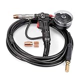
- Light Fabrications Made Easier: Experience a smooth welding experience with our Miller Spoolmate 150 Spool Gun; With its consistent wire feed & 20 ft of cable reach & accessibility, our welding spool gun is ideal for for home hobbyists & light fabricators; Comes with with a nozzle & extra contact tips
- Welding Versatility: Designed for MIG (MGAW) welding, our MIG spool gun lets you weld both 4000 & 5000 series aluminum wire; Our Miller aluminum spool gun welder also works with steel & stainless steel wires, making it ideal for various applications
- Spool Visibility for Maximum Efficiency: Thanks to our Miller spool gun’s clear cover, you’ll always know how much wire you have left; Avoid unexpected interruptions during your projects to help enhance both your efficiency & productivity at the job
- Heavy-Duty Durability: Our MIG welder spool gun is crafted with tough & durable parts, including a heavy-duty drive motor & a cast aluminum gearbox; Project after project, you can count on our aluminum welding spool gun’s reliability & performance
- Hook-Up Recommendations: Our aluminum welding gun runs on 150A at 60 percent duty cycle & is compatible with the Millermatic 211 Auto-Set with MVP, Millermatic 211, Multimatic 200 (with serial number MF364047N), Multimatic 215, Syncrowave 210 TIG (Retrofit & accessory kit required) & Syncrowave 210 TIG/MIG Complete; Power cord not included
Last update on 2026-07-01 / Affiliate links / Images from Amazon Product Advertising API
MDX-100 Consumables
The included MDX-100 uses Miller MDX consumables. Confirm the gun model and wire size before ordering tips, nozzles, diffusers, or liners. A confirmed WSP Miller MDX-100 MIG gun parts breakdown is available for visual part matching.
| Part type | Part numbers | Use note |
|---|---|---|
| Contact tips | T-M023, T-M030, T-M035, T-M045, T-M047 | Match tip bore to wire diameter |
| Nozzles | NS-M1200B, NS-M1200C, NS-MFLX | Brass, copper, or gasless nozzle |
| Diffuser | D-M100 | Replace if gas ports clog or threads are damaged |
| Liners | LM1A-15, LMD2A-15, LMD3A-15 | Match liner range to wire size |
Common Wrong-Part Mistakes
- Ordering Miller FasTip, M-Series, or Bernard Centerfire consumables for the MDX gun. Miller states these are not compatible with MDX Series guns.
- Buying Spoolmate 100 parts for a Spoolmate 150 gun.
- Assuming every WP-17 torch has the correct 25 mm flow-through Dinse connector.
- Ordering a liner only by length without checking wire diameter range.
- Using the wrong drive roll groove for solid wire versus flux-cored wire.
Inspection Steps Before Ordering
- Read the gun label: MDX-100, Spoolmate 100, Spoolmate 150, or Weldcraft A-150.
- Confirm wire size: .023, .030, .035, .045, or 3/64 in.
- Check connector style: MIG gun connection, spool gun direct connect, or 25 mm Dinse TIG connector.
- Inspect nozzle threads, diffuser face, tip bore, liner end, drive roll groove, and cable strain relief.
- For TIG, verify torch, collet, collet body, cup size, tungsten diameter, pedal type, and gas hose setup.
Common Symptoms and Likely Accessory Causes
| Symptom | Likely cause | Check first |
|---|---|---|
| Burnback | Worn tip, poor feed path, wrong tension | Tip bore, liner, drive roll pressure |
| Birdnesting | Liner drag, wrong groove, loose drive setup | Drive roll, liner match, gun cable bends |
| Porosity | Gas issue or clogged diffuser/nozzle | Gas flow, D-M100 diffuser, nozzle spatter |
| Aluminum feeding problems | Wrong spool gun or wire family | Spoolmate model and wire alloy |
| TIG arc will not control correctly | Foot control mismatch or connector issue | 301580 wireless or 301589 wired pedal setup |
Field Fix vs Proper Fix
A field fix is cleaning spatter from the nozzle, trimming wire, reseating the liner, and reducing sharp gun bends. The proper fix is replacing the worn tip, diffuser, liner, drive roll, or gun accessory with the correct Miller-listed part number. Do not keep increasing drive tension to overcome a bad liner; that usually creates more feed damage.
Safety Notes
- Disconnect input power before opening panels or changing internal drive components.
- Shut off shielding gas before changing regulators, hoses, or TIG kits.
- Use proper eye, hand, and respiratory protection when welding, grinding, or cutting contaminated metal.
- Do not exceed rated duty cycle for the gun, spool gun, torch, or machine input voltage.
Related Parts Breakdown
Use the confirmed WSP replacement gun parts diagram for MDX-100 consumable identification. Related MDX family reference: Miller MDX-250 MIG gun parts breakdown.