Tag: maintenance buying

  • Western Enterprises 69 Regulator Inlet Nipple, Oxygen, CGA-540 x 1/4″ NPT, 3″ Length, Brass: Product Breakdown

    Western Enterprises 69 Regulator Inlet Nipple, Oxygen, CGA-540 x 1/4″ NPT, 3″ Length, Brass: Product Breakdown

    Product not found.
    “>Western Enterprises 69 Regulator Inlet Nipple, Oxygen, CGA-540 x 1/4" NPT, 3" Length, Brass

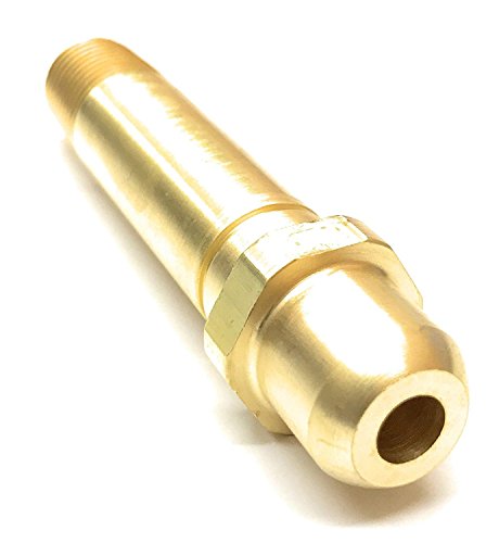
    The Western Enterprises 69 regulator inlet nipple is a gas apparatus support part used in oxygen service. Based on the product listing provided, it is a brass fitting with a CGA-540 cylinder connection on one end and 1/4" NPT threads on the regulator-side end. The listed length is 3 inches. For buyers, technicians, and maintenance teams, the important question is not only what the part is, but whether it matches the connection pattern, service gas, and installation method required on the equipment in front of you.

    Key Takeaways

    • Use this part only where the gas connection pattern matches the existing equipment.
    • The listing identifies oxygen service and CGA-540 to 1/4" NPT interface geometry.
    • Do not assume compatibility from thread size alone; verify the regulator inlet, cylinder valve, and sealing method.
    • Brass is commonly used in gas apparatus support, but the application still depends on the exact service conditions. Unknown (Verify) if your system has special material requirements.
    • Installation quality depends on clean threads, correct orientation, and leak verification after assembly.

    What the Part Does

    This inlet nipple bridges a cylinder-side oxygen connection to regulator-side plumbing. In practical terms, it is a transition fitting. One side connects to CGA-540 oxygen cylinder hardware, while the other side provides 1/4" NPT male or female connection geometry as listed by the product description. If your system uses a different regulator inlet style, a different CGA designation, or another thread form, do not force the fit. Verify the actual connection standard before ordering or installing.

    Fit and Application Checks

    Before installing any regulator inlet nipple, use a simple verification sequence:

    1. Check the gas service. Confirm the system is oxygen service. Do not mix fuels, inert gases, or mixed-service assemblies without confirming the full setup.
    2. Inspect the cylinder connection. Verify the cylinder valve connection is CGA-540, not a different CGA pattern. Do not rely on visual similarity alone.
    3. Inspect the regulator inlet. Confirm the regulator-side port accepts 1/4" NPT plumbing as listed. Unknown (Verify) if your regulator uses a different thread form or sealing method.
    4. Verify thread condition. Clean both male and female threads. Look for damaged starts, cross-threading, burrs, or contamination.
    5. Verify length and clearance. The listed length is 3 inches. Check whether that length gives proper clearance to the regulator body, cabinet, wall, or manifold frame.

    Troubleshooting Support: Common Problems to Check

    If the assembly will not seal or does not fit as expected, isolate the issue before replacement.

    • Problem: Thread engagement stops early.
      Check whether the thread form is correct. Verify you are not mixing NPT with another pipe thread standard. Inspect for debris, sealant buildup, or damaged starts.
    • Problem: Leak at the joint.
      Check sealing surfaces, thread condition, and assembly torque method used on the regulator connection. Verify the fitting is intended for the exact service arrangement. Do not assume additional sealant will fix a mismatch.
    • Problem: Wrong cylinder connection.
      Check the cylinder valve outlet marking. CGA-540 must be confirmed directly on the equipment or documentation.
    • Problem: Physical interference after installation.
      Verify the 3-inch length provides enough space for wrench access and hose routing. If not, select a different fitting arrangement that is approved for the system. Unknown (Verify).

    Inspection Prior to Service

    Use these checks every time the fitting is received or reinstalled:

    • Inspect the brass body. Look for cracks, deep scratches, corrosion, dents, or machining defects.
    • Inspect the threads. Confirm threads are clean and uniform from end to end.
    • Inspect for contamination. Keep oil, grease, and shop debris away from oxygen service parts.
    • Verify part identity. Match the product label, connection pattern, and service description before use.

    Product Breakdown

    The Western Enterprises 69 regulator inlet nipple, as listed, is a brass oxygen-service fitting with CGA-540 cylinder connection geometry, 1/4" NPT regulator-side threading, and a 3-inch overall length. That is the level of certainty available from the provided source. Do not add assumptions about pressure rating, certifications, seal type, or specific regulator brand compatibility unless those details are confirmed in the equipment documentation or by the manufacturer. Unknown (Verify) for any unpublished technical specification.

    For maintenance buyers, the value of this part is straightforward: it is a connection component. It is not a complete regulator, not a cylinder valve, and not a universal adapter. The part only solves the interface problem if the rest of the assembly is already designed around CGA-540 and 1/4" NPT geometry.

    Safety Notes

    • Use oxygen-service parts only in oxygen service.
    • Keep all fittings clean and free of oil, grease, and shop contamination.
    • Do not guess on thread type or gas connection standard.
    • Depressurize and isolate the system before removal or installation.
    • After assembly, verify for leaks using the approved site procedure.

    FAQ

    Is this fitting a universal oxygen regulator adapter?
    No. It is listed as a CGA-540 to 1/4" NPT regulator inlet nipple. Universal compatibility is not stated. Verify the exact equipment connection before purchase.

    Can I use it on any regulator with a 1/4" NPT port?
    Not automatically. The cylinder-side connection still has to match CGA-540, and the regulator assembly must be intended for oxygen service. Verify both ends of the system.

    Does brass mean it is suitable for every oxygen application?
    No. Brass is the listed material, but system requirements vary. Unknown (Verify) for any special material, cleaning, or approval requirement beyond the product listing.

    What should I check first if the joint leaks?
    Check thread condition, correct connection standard, clean assembly surfaces, and the regulator-side sealing method. Do not overtighten in an attempt to compensate for a mismatch.

    Sources Checked

    • ArcWeld product listing provided in the task: Western Enterprises 69 Regulator Inlet Nipple, Oxygen, CGA-540 x 1/4" NPT, 3" Length, Brass
    • Provided source URL referenced in the task:
      Product not found.

    Related Arc Weld Part

    Western Enterprises 69 Regulator Inlet Nipple, Oxygen, CGA-540 x 1/4" NPT, 3" Length, Brass

    Western Enterprises 69 Regulator Inlet Nipple, Oxygen, CGA-540 x 1/4" NPT, 3" Length, Brass

    The Western Enterprises 69 regulator inlet nipple is a brass fitting used to connect an oxygen regulator inlet to a CGA-540 oxygen cylinder connection, with a 1/4" NPT threaded end for regulator-side plumbing. Built for durability and corrosion resistance in oxygen service applications.

    View at Arc Weld Store
  • Tillman 1477 TrueFit Cut Resistant Premium Goatskin Performance Gloves, Large: Replacement Part Breakdown

    Welders and maintenance buyers do not need marketing language when selecting gloves. They need a glove that fits, holds up to the task, and is replaced before wear becomes a safety problem. The Tillman 1477 TrueFit Cut Resistant Premium Goatskin Performance Gloves, Large, should be evaluated the same way: by fit, stitch integrity, palm wear, finger wear, and whether the glove still supports the job without reducing dexterity.

    This guide is a practical breakdown for inspection, replacement, and support decisions. It does not assume performance beyond what is verifiable from the product listing. Where technical details are not confirmed here, they are marked Unknown (Verify).

    Key Takeaways

    • Check fit first. A glove that is too loose can reduce grip control and catch on edges.
    • Inspect goatskin wear points before every shift: fingertips, thumb crotch, palm, and seams.
    • Replace gloves when liner exposure, seam opening, or palm thinning affects safe use.
    • Do not assume cut resistance equals protection from all hazards. Confirm the glove is appropriate for the task.
    • Use the product listing as a starting point for selection, then verify size and task fit in the field.

    Product and Part Breakdown

    The product identified for this guide is the Tillman 1477 TrueFit Cut Resistant Premium Goatskin Performance Gloves, Large, ASIN B08BSTWP7P. The listing name indicates a goatskin performance glove with cut-resistant construction, but detailed construction data such as liner material, reinforcement pattern, cuff length, and certification status are Unknown (Verify) from the information provided here.

    For maintenance buyers, the important part is not just the glove name. It is whether the glove matches the work envelope. Verify the following before placing into service:

    • Size: Large, as listed.
    • Hand fit: full finger reach without excess slack at fingertips.
    • Grip: dry-hand and tool-hand contact with no rolling in the palm.
    • Dexterity: ability to hold small consumables, torch leads, hand tools, and fasteners.
    • Coverage: verify cuff and wrist coverage for the specific job.

    If you need a product reference for the listing, use the approved product shortcode:

    No products found.

    . Do not use that as a substitute for inspection or task verification.

    Check, Inspect, Verify: Pre-Use Routine

    Check the glove condition before the shift starts. Look for dirt buildup, embedded metal splatter, cuts, and stiffness that can limit hand movement.

    Inspect the high-wear zones closely:

    • Fingertips for pinholes, split seams, or worn-through leather.
    • Thumb crotch for tearing from repeated clamp, rod, or tool handling.
    • Palm surface for thinning, glazing, or cracking.
    • Seams along the fingers and back of hand for opening stitches.
    • Cuff and wrist area for fraying or edge damage.

    Verify the glove still matches the job. If the glove is intended for welding support, confirm that the current task does not require a different glove type, longer cuff, or higher heat protection. Unknown (Verify) whether this glove is suited for direct welding arc exposure, heavy spatter, or prolonged high-heat contact. Do not assume.

    Troubleshooting Support for Wear and Fit Problems

    Problem: glove feels loose at the fingers.
    Check whether the glove is oversized or stretched from use. Inspect for material softening and finger tip collapse. Verify that the user can still handle fasteners and torch controls without excess movement.

    Problem: grip feels slick.
    Inspect the palm surface for oil, coolant, grinding dust, or wear glazing. Clean the glove only if the care method is allowed by the manufacturer. If grip remains poor after cleaning, replace the glove.

    Problem: seam failure starts at the thumb or palm.
    Check for repetitive torque loads, tool carry habits, and pinch points. Verify whether a different glove style or reinforcement pattern is required. If the seam has opened, the glove is out of service.

    Problem: glove still looks usable but comfort dropped.
    Inspect for internal lining bunching, hardening from contamination, or shrinkage from cleaning or heat exposure. Verify whether the glove still allows full hand closure. Loss of comfort often shows up before visible failure.

    Replacement Decision Rules

    Replace the glove when any of the following are true:

    • There are holes, split seams, or exposed inner layers.
    • Leather has thinned enough that protection is reduced.
    • Finger movement is restricted by hardening or deformation.
    • Contamination cannot be removed and affects grip or handling.
    • The glove no longer fits the worker safely.

    For buyers managing stock, standardize replacement based on condition, not calendar time alone. A glove used for sharp edges, abrasive handling, or frequent tool contact will wear out faster than a glove used for light support tasks.

    How to Evaluate Before Buying

    Before placing this glove in a cart, verify three things: task fit, size fit, and replacement rhythm. Task fit means the glove suits the actual work. Size fit means the Large size works for the intended user without reducing control. Replacement rhythm means the glove can be inspected and removed from service before damage reaches the hand.

    If you are comparing this product to another Tillman glove style, use the related internal reference for context only: Tillman 48 MIG Gloves Review: Goatskin Fleece Comfort. That article is a separate product reference and should not be treated as a compatibility match for this glove.

    Safety Notes

    • Do not use damaged gloves for sharp-edge handling, hot work, or general shop tasks.
    • Verify the glove type against the hazard before use. Cut-resistant does not mean cut-proof.
    • Keep gloves free of oil and grinding residue where possible.
    • Remove from service if stitches open or leather is worn through.
    • Do not rely on a glove listing alone for compliance decisions.

    FAQ

    Is the Tillman 1477 suitable for welding?
    Unknown (Verify). The product name suggests performance use and cut resistance, but direct welding suitability, heat resistance, and spatter performance are not confirmed here.

    What should buyers check first on arrival?
    Check size marking, inspect seams, and verify that the glove has no shipping damage, contamination, or obvious manufacturing defects.

    When should the glove be replaced?
    Replace it when leather thins, seams open, holes appear, or fit changes enough to reduce control.

    Can this glove be treated as a universal shop glove?
    No. Verify the task. Different jobs may require different levels of dexterity, coverage, or thermal protection.

    Sources Checked

    • Provided Amazon product reference for Tillman 1477 TrueFit Cut Resistant Premium Goatskin Performance Gloves, Large, ASIN B08BSTWP7P
    • Provided internal link: Tillman 48 MIG Gloves Review: Goatskin Fleece Comfort

    This guide is intended as a field-use buying and inspection reference. Confirm any uncertain construction or performance details directly from the current product listing or manufacturer documentation before purchase or issue.

    Disclosure: As an Amazon Associate, Weld Support Parts may earn from qualifying purchases.

    Related Weld Support Guides

  • Norton 43785, 4.5″ x 1/4″ x 5/8-11 in. Gemini XXL, Pack of (10): Product Breakdown

    Norton 43785, 4.5″ x 1/4″ x 5/8-11 in. Gemini XXL, Pack of (10): Product Breakdown

    Product not found.
    “>Norton 43785, 4.5" x 1/4" x 5/8-11 in. Gemini XXL, Pack of (10)

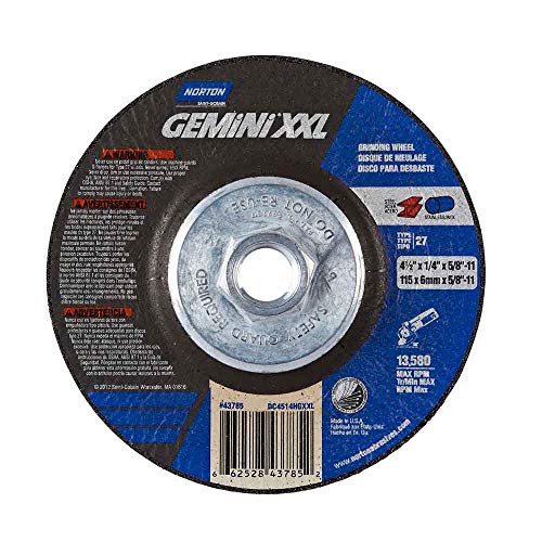
    Depressed center grinding wheels are standard consumables in weld shops, fabrication bays, and maintenance crews that spend time on right-angle grinding. The Norton 43785, 4.5″ x 1/4″ x 5/8-11 in. Gemini XXL, Pack of (10) is one of those shop items that needs to be checked as a fit-and-use decision, not just a part number match. For buyers and end users, the practical questions are simple: does it fit the grinder, does it match the task, and is it being used within the tool’s guard and speed limits? The product listing identifies this as a depressed center wheel. Beyond that, any material-specific or performance-specific detail is Unknown (Verify) unless confirmed on the vendor page or in your own purchasing record.

    Key Takeaways

    • This is a depressed center wheel, commonly referred to as Type 27, 28, or 29 depending on shape and use case.
    • The 5/8-11 mounting thread is a key fit check for the grinder spindle. Verify the tool spindle before ordering.
    • Pack size is 10 wheels. Confirm your usage rate before committing to bulk inventory.
    • The wheel is intended for right-angle grinding applications, but the exact work range for your process is Unknown (Verify).
    • Use the product page as the primary source for the part number and listed configuration, and verify all grinder compatibility in the field.

    What This Part Is Used For

    Depressed center wheels are built to let the flange or lock nut recess into the wheel body. That shape helps the operator approach a workpiece at an angle without the hardware interfering with the grind. In practice, this makes the wheel useful for weld cleanup, edge dressing, material removal, and other severe right-angle grinding tasks. The exact applications still depend on the wheel specification, machine rating, and operator technique. If the job involves heavy stock removal, root pass cleanup, bevel preparation, or surface blending, verify the wheel grade and intended use before installation.

    Do not assume that all 4-1/2 inch grinding wheels behave the same. Diameter alone does not guarantee compatibility with a given grinder, guard, or work method. Verify all three: wheel size, thread fit, and the machine’s rated speed.

    Product and Parts Breakdown

    The product title gives the key buying identifiers:

    • Brand: Norton
    • Part number: 43785
    • Wheel size: 4.5 inch by 1/4 inch
    • Mount: 5/8-11
    • Wheel style: Gemini XXL
    • Pack quantity: 10

    Everything beyond those listed identifiers should be treated as Unknown (Verify) unless your sourcing record or product page confirms it. That includes exact abrasive composition, application rating, grain type, maximum RPM, and material compatibility.

    If your maintenance team is comparing this wheel to other Norton Gemini wheels, use the internal review as a related reference point only: Norton Gemini Fast Cut Grinding Wheel Review (4-1/2″ × 1/4″ × 7/8″, Pack of 25). That article may help with broader shopping context, but it is not a substitute for checking the exact part number and mount size.

    How to Check Fit Before You Buy or Install

    Use a short verification routine before the wheel is accepted into service:

    1. Check the spindle thread. Verify the grinder spindle is 5/8-11. If it is not, stop and select the correct mount.
    2. Inspect wheel diameter. Confirm the tool guard is sized for a 4.5 inch wheel.
    3. Inspect thickness. The title shows 1/4 inch. Verify your guard, flange stack, and work access can accommodate that thickness.
    4. Verify tool speed rating. Match the grinder’s rated speed to the wheel’s label. If the wheel label is unavailable, treat the speed rating as Unknown (Verify) and do not install until confirmed.
    5. Inspect the wheel face. Reject any wheel with cracks, chips, moisture damage, distortion, or obvious contamination.

    Troubleshooting Support

    If the wheel is not performing as expected, work through the following checks before blaming the wheel.

    Wheel does not fit the grinder

    • Check: spindle thread size.
    • Inspect: flange and lock nut configuration.
    • Verify: the grinder is designed for a 5/8-11 mounted wheel, not another arbor pattern or quick-change system.

    Wheel feels unstable or vibrates

    • Check: wheel seating on the flange.
    • Inspect: damaged flanges, dirty mounting surfaces, bent spindle, or guard interference.
    • Verify: the wheel is mounted in the correct orientation and fully tightened per the grinder manufacturer instructions.

    Grinding rate is lower than expected

    • Check: the workpiece material and condition.
    • Inspect: glazing, loading, or edge wear on the wheel face.
    • Verify: the wheel type is appropriate for the material and the operator is using the correct angle and pressure. If the wheel type is unknown, treat the performance expectation as Unknown (Verify).

    Safety Notes

    • Wear face protection, eye protection, gloves, hearing protection, and suitable clothing.
    • Use the grinder guard. Do not remove or bypass it.
    • Do not exceed the wheel’s marked speed rating. If the rating is unavailable, stop and verify before use.
    • Do a brief no-load spin check after installation and stand clear of the wheel plane.
    • Remove damaged wheels from service immediately.

    Buyer Guidance for Maintenance Teams

    For storeroom control, pack quantity matters. A pack of 10 can reduce reordering time, but only if the wheel is a known fit for your most common grinders. If your fleet includes mixed spindle sizes, do not assume this part will cover all units. Standardize by machine class, then stock accordingly. If the wheel is intended for a specific task cell, label the bin with both the part number and the confirmed grinder model after verification.

    For comparison shopping, use product title, spindle size, and wheel diameter as the primary controls. Do not build a purchase decision from brand name alone. If a specification is not stated in the source provided, mark it Unknown (Verify) in your internal record.

    FAQ

    Q: Is the Norton 43785 wheel a Type 27 wheel?
    A: The listing describes a depressed center wheel. Depressed center wheels are commonly referred to as Type 27, 28, or 29 depending on shape and use. Exact shape designation for this part is Unknown (Verify) unless the product page states it directly.

    Q: Will this wheel fit any 4.5 inch grinder?
    A: No. You must verify spindle thread, guard clearance, and machine speed rating. A 4.5 inch wheel with a 5/8-11 mount will not fit every grinder.

    Q: Can this wheel be used for cutting as well as grinding?
    A: The source describes it as a depressed center wheel used for grinding and cutting applications, but exact task approval depends on the wheel’s verified label and your tool setup. Confirm before use.

    Q: Is the abrasive type or material rating confirmed here?
    A: No. Abrasive formulation, work material rating, and performance limits are Unknown (Verify) from the provided source.

    Sources Checked

    • ArcWeld product page: Norton 43785, 4.5″ x 1/4″ x 5/8-11 in. Gemini XXL, Pack of (10)
    • Internal related article: Norton Gemini Fast Cut Grinding Wheel Review (4-1/2″ × 1/4″ × 7/8″, Pack of 25)

    All uncertain technical details in this draft are marked Unknown (Verify). Verify actual wheel labeling, machine compatibility, and operating limits before purchase or use.

    Related Arc Weld Part

    Norton 43785, 4.5" x 1/4" x 5/8-11 in. Gemini XXL, Pack of (10)

    Norton 43785, 4.5" x 1/4" x 5/8-11 in. Gemini XXL, Pack of (10)

    Depressed center wheels may also be referred to as raised hub wheels or by their shape designation Type 27, 28 or 29, with Type 27 being the most popular. The depressed center design allows the flange/lock nut to recess within the wheel so that it can be used for various grinding and cutting applications. Depressed center wheels are designed to handle the most severe right angle grinding applications from heavy st…

    View at Arc Weld Store

    Related Weld Support Guides

  • Washington Alloy 308L-16 Stick Electrode 10 LB. Package (3/32″ – 10 LBS.): Replacement Part Breakdown

    Washington Alloy 308L-16 stick electrodes are commonly selected for stainless welding support work where an E308L-16 classification is being considered. For maintenance buyers and welders, the main job is not just finding a box with the right label. The job is verifying the base metal, joint condition, electrode size, storage condition, and the actual welding procedure before the part is issued to the floor.

    This article is a practical breakdown for the Washington Alloy 308L-16 Stick Electrode 10 LB. Package (3/32″ – 10 LBS.) B08232Q6P7 product reference. It focuses on what to check, how to inspect the package and setup, and how to avoid ordering the wrong replacement item when the weld callout is incomplete or unclear.

    Key Takeaways

    • 308L-16 is a stainless stick electrode designation. Final procedure approval still depends on the job spec and base metal.
    • The 10 lb package and 3/32″ diameter must both match the application and the holder setup.
    • Do not assume stainless electrode interchangeability. Verify the alloy family, deposit requirements, and service environment.
    • If the welding document is unclear, treat the selection as Unknown (Verify) until the procedure or supervisor confirms it.

    What this product reference means

    The product name identifies a Washington Alloy 308L-16 stick electrode in a 10 lb package, with a 3/32″ diameter noted in the title. Beyond that, details such as exact coating behavior, recommended polarity, packaging style, and any application limits are Unknown (Verify) unless confirmed by the governing spec, supplier data, or the job procedure.

    For shop use, the important point is that the label alone is not a complete purchasing decision. Use the electrode classification as a starting point, then verify the following:

    • Base metal grade and condition
    • Required deposit chemistry
    • Joint design and access
    • Machine output range and stinger compatibility
    • Storage and exposure history of the electrodes

    Check before you buy

    Inspect the weld callout. Confirm whether the job actually calls for 308L-16 or a different stainless electrode classification. If the print only says “stainless rod,” stop and verify. That instruction is not enough for a controlled purchase.

    Verify diameter. The 3/32″ size must fit the amperage range, joint access, and operator skill level. If the work is thin material, tight corners, or positional welding, the diameter choice may need review. Unknown (Verify) until the procedure is checked.

    Check the package count. A 10 lb box matters to stocking, issue control, and production planning. Make sure the order quantity aligns with burn rate and whether the electrode will be shared across jobs or kept for a single work order.

    Inspect storage conditions. If the electrodes have been exposed to moisture, damaged packaging, or dirty storage, do not issue them blindly. Open package condition, visible contamination, and label integrity should be checked before use.

    Troubleshooting and support checks

    Problem: arc starts poorly or sticks excessively. Check the electrode holder, cable condition, machine settings, and the electrode condition itself. Verify that the current delivery is stable and that the rods are dry and clean. If the machine is correct but the issue remains, the procedure may be wrong for the material.

    Problem: weld appearance is inconsistent. Inspect work lead placement, joint cleanliness, and travel control. Stainless stick work is sensitive to surface contamination. Check for mill scale, oil, paint, and oxide on the base metal. Verify that the joint was prepared to the required level before welding began.

    Problem: the electrode seems to be the wrong choice. Stop and compare the job requirements to the product classification. Check whether the base material is stainless, whether dissimilar metal is involved, and whether corrosion resistance or service temperature requirements apply. If any of those are unclear, mark the selection Unknown (Verify) and escalate.

    Problem: stock label does not match the work order. Inspect the carton label, internal part number, and issue documentation. Verify the ASIN reference only as a catalog identifier; do not treat it as a procedure approval.

    Product and parts breakdown

    The available product reference for this article is the Washington Alloy 308L-16 Stick Electrode 10 LB. Package (3/32″ – 10 LBS.) with ASIN B08232Q6P7. No additional part breakdown, kit contents, or accessory list is confirmed here. Unknown (Verify) for any claim about included extras, proprietary features, or special packaging beyond the stated product name.

    For buyers, the practical breakdown is simple:

    • Electrode classification: 308L-16
    • Package size: 10 lb
    • Diameter noted in title: 3/32″
    • Catalog reference: B08232Q6P7

    If your purchasing system requires a procedure match, job number, or approved filler list, verify those against internal documents before release.

    Support links for selection checks

    Use the WSP blog resources below as support references for stick welding setup and electrode handling. These are starting points for selection and shop practice, not guaranteed procedure approvals.

    For broader stainless and filler selection work, compare the job requirements against the available WSP resources and internal purchasing controls. If the application is not clearly defined, do not guess.

    Safety notes

    • Verify the work area is ventilated before welding stainless materials.
    • Check PPE condition before issue: helmet, gloves, jacket, and respiratory controls if required by site policy.
    • Inspect the electrode holder and cables for damaged insulation before energizing the circuit.
    • Keep electrodes dry and store them per site practice and manufacturer guidance when available.
    • Do not use uncertain filler selection as a substitute for a qualified welding procedure.

    FAQ

    Is Washington Alloy 308L-16 the right electrode for any stainless job?
    No. It may be suitable for some stainless applications, but the base metal, joint design, service condition, and procedure must be verified first.

    Does the 3/32″ size work for every stick welding setup?
    No. Diameter must match the machine output, joint access, and the required deposition rate. Verify before issue.

    Can I use the Amazon product title as proof of procedure approval?
    No. The title is a catalog reference only. Approval comes from the job spec, WPS, supervisor direction, or other controlled documentation.

    What should I do if the exact filler requirement is unclear?
    Mark it Unknown (Verify), check the print or WPS, and confirm with welding supervision or engineering before ordering or issuing the electrode.

    Sources Checked

    • Provided product reference: Washington Alloy 308L-16 Stick Electrode 10 LB. Package (3/32″ – 10 LBS.)
    • Provided ASIN reference: B08232Q6P7
    • Allowed internal links listed in the task

    Matched Replacement Option

    No products found.

    Disclosure: As an Amazon Associate, Weld Support Parts may earn from qualifying purchases.

    Related Weld Support Guides

  • Lincoln Electric SuperArc LA-90 MIG Wire ER80S-D2/ER90S-D2, 0.045″, 500 lb Drum (ED001378): Product Breakdown

    Lincoln Electric SuperArc LA-90 MIG Wire ER80S-D2/ER90S-D2, 0.045″, 500 lb Drum (ED001378): Product Breakdown

    Product not found.
    “>Lincoln Electric SuperArc LA-90 MIG Wire ER80S-D2/ER90S-D2, 0.045", 500 lb Drum (ED001378)

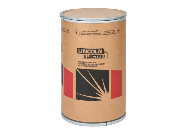
    Lincoln Electric SuperArc LA-90 MIG Wire ER80S-D2/ER90S-D2, 0.045″, 500 lb Drum (ED001378) is a low-alloy GMAW wire intended for higher-strength steel applications where the filler metal classification matters as much as the base metal and shielding gas. For buyers and weld support teams, the main point is simple: this is not a general-purpose wire. It is a classification-driven consumable that should be matched to the procedure, joint design, shielding gas, and deposit property requirements before release to production.

    Key Takeaways

    What to Verify Before You Buy

    For maintenance buyers, the first filter is whether the wire classification matches the job. Check the WPS, base metal spec, and required deposited mechanical properties. ER80S-D2 and ER90S-D2 are not interchangeable by assumption. If your procedure calls for one range, confirm that the wire classification on the spool label and certification paperwork matches that requirement.

    Inspect: the wire package size, feed system capability, and storage space for a 500 lb drum. Large drums are efficient for high-volume work, but they create handling and feed-path requirements that smaller spools do not.

    Verify: drive roll setup, liner condition, inlet guide size, gun routing, and whether your feeder is configured for drum use. Unknown (Verify) if your feeder, drum adapter, or wire delivery kit is suitable for this package size.

    Support Check: Feedability and Setup

    Low-alloy solid wire performance is often limited by setup errors, not the wire itself. If the arc is unstable or feed speed is inconsistent, start with the wire path.

    If you need a more detailed feed system reference, use this internal guide: Lincoln Drive Roll Pressure Adjustment Guide. It covers wire feed slip, burnback, birdnesting, and wire shaving fixes.

    Shielding Gas and Polarity

    The product description identifies DC+ polarity and common use with 100% CO2 and argon/oxygen blends. That helps narrow selection, but it does not replace a procedure. Gas choice affects arc characteristics, spatter level, penetration profile, and bead shape. The exact procedure may require a specific blend, flow rate, or torch setup. Unknown (Verify) unless your WPS or governing document specifies it.

    Check: regulator condition, flow meter accuracy, hose integrity, and gas delivery at the gun. A wire can be correct and still perform poorly if shielding is inconsistent.

    Verify: polarity at the machine before loading the wire into production. Reversed polarity can create immediate performance problems and misleading troubleshooting.

    WSP Lookup and Filler Metal Selection

    If you are building a purchasing or support decision, use the available selection tools as starting points only. They help narrow the search, but they do not guarantee procedure approval.

    Use any filler metal finder output as a selection starting point, not as a substitute for your WPS, base metal qualification, or code requirement.

    Product and Parts Notes

    The allowed product for this draft is the ArcWeld listing for Lincoln Electric SuperArc LA-90 MIG Wire ER80S-D2/ER90S-D2, 0.045″, 500 lb Drum (ED001378). Use the ArcWeld product page when you need the vendor-facing product record and ordering reference.

    Product not found.

    “>View the ArcWeld product page

    The product shortcode provided for internal use is:

    Lincoln Electric SuperArc LA-90 MIG Wire ER80S-D2/ER90S-D2, 0.045", 500 lb Drum (ED001378)

    Lincoln Electric SuperArc LA-90 MIG Wire ER80S-D2/ER90S-D2, 0.045", 500 lb Drum (ED001378)

    SuperArc® LA-90™ is a premium, copper-coated low-alloy MIG (GMAW) wire from Lincoln Electric designed to meet 80,000–90,000 psi tensile strength requirements for higher-strength steel applications. Classified to AWS A5.28 ER80S-D2 / ER90S-D2, LA-90 delivers strong, consistent as-welded mechanical performance across common shielding gas mixes, including 100% CO₂ and argon/oxygen blends, with DC+ polarity. This list...

    View at Arc Weld Store

    Do not assume additional compatibility, certifications, or performance values beyond what is stated in the product record. Unknown (Verify) if a specific feeder, gun, or procedure package is not documented.

    Practical Troubleshooting Sequence

    1. Check the wire classification on the label against the WPS.
    2. Inspect the feed path from drum to contact tip.
    3. Verify polarity, gas type, and gas flow.
    4. Check the contact tip for wear or mismatch.
    5. Inspect the joint prep, mill scale, rust, oil, and moisture.
    6. Verify whether the issue follows the wire or stays with the machine setup.

    If the deposit profile is not meeting expectations, do not jump straight to a different wire class. First confirm that the setup matches the intended procedure. Many apparent filler metal problems are actually feed issues, shielding issues, or base metal prep issues.

    Safety Notes

    FAQ

    Is this wire for general mild steel welding?
    Not by default. It is classified as ER80S-D2 / ER90S-D2 and should be matched to the procedure and strength requirements. Unknown (Verify) for any mild steel application unless the WPS allows it.

    What polarity is listed for this wire?
    The product description identifies DC+ polarity.

    Can I use it with any shielding gas?
    No. The listing mentions common use with 100% CO2 and argon/oxygen blends, but the actual approved gas depends on your procedure. Treat gas references as a starting point only.

    What should I check first if feed is unstable?
    Check drive roll pressure, liner condition, contact tip wear, cable routing, and drum brake tension before replacing the wire.

    Sources Checked

    Related Weld Support Guides

  • Read with Kindle Unlimited