Tag: buyer guide

  • Harris 60/40 1/16 in. x 8 oz. Leaded Rosin Core Solder, Pack of (1): Replacement Part Breakdown

    Harris 60/40 1/16 in. x 8 oz. Leaded Rosin Core Solder, Pack of (1) is a consumable used in general soldering work where a leaded rosin core solder is specified by the job. For welders, fabricators, maintenance buyers, and support teams, the main task is not finding a “replacement part” in the mechanical sense. It is verifying that the solder form, alloy type, and core chemistry match the application before use.

    This guide focuses on practical inspection and support checks. It does not assume approval for any specific procedure. If your application is controlled by a work instruction, electrical standard, or customer specification, follow that first.

    Key Takeaways

    • Harris 60/40 indicates a leaded solder alloy mix, but exact process approval depends on the job requirement.
    • Rosin core solder is selected for soldering work, not welding or brazing operations.
    • Verify diameter, core type, and package condition before use.
    • Use this product only where leaded solder is allowed. If lead restriction applies, stop and verify an approved alternative.
    • When uncertain about fit or process acceptance, record Unknown (Verify) and confirm against the job spec or supervisor.

    What to Inspect Before Use

    Consumables are often blamed for poor joints when the issue is actually preparation, surface condition, or incorrect process selection. Before opening the package, run these checks.

    Check the label

    • Verify alloy designation: Confirm the package is marked Harris 60/40.
    • Verify diameter: The listing states 1/16 in., but do not assume all spools in the field match. Inspect the spool label directly.
    • Verify net weight: The listing states 8 oz. Confirm the actual package you received.
    • Verify core type: Rosin core should be clearly identified. If it is not, treat it as Unknown (Verify).

    Inspect the spool and wire

    • Check for kinks, crushed edges, or broken wrap that can affect feedability.
    • Look for oxidation, discoloration, or contamination on the solder surface.
    • Confirm the solder wire is not stuck together or deformed on the spool.

    Verify storage condition

    • Confirm the spool was stored dry and away from chemical exposure.
    • Check for signs of moisture, corrosion, or packaging damage.
    • If storage history is unknown, treat condition as Unknown (Verify) until tested on a sample joint.

    Troubleshooting and Support Checks

    If the solder does not feed well or the joint quality is poor, isolate the cause before replacing the spool.

    Support check 1: Poor wetting

    • Inspect: Surface cleanliness, oxide removal, and tip condition.
    • Verify: The soldering iron temperature is appropriate for the work. Exact setpoint is Unknown (Verify) because it depends on the assembly and procedure.
    • Check: Whether flux residue or contamination is preventing wetting.

    Support check 2: Grainy or dull joints

    • Inspect: Joint movement during cooling.
    • Verify: The parts were held stationary until solidified.
    • Check: Whether the joint was reheated after initial solidification, which can create a weak appearance.

    Support check 3: Solder does not flow through the joint

    • Inspect: Part fit-up and gap size.
    • Verify: The solder type and diameter match the hand skill level and joint size. If not confirmed, mark Unknown (Verify).
    • Check: Whether the base metals were prepped and tinned correctly.

    Support check 4: Excess residue or cleaning problems

    • Inspect: Residue type after the joint is complete.
    • Verify: Cleaning method is compatible with the assembly and flux residue.
    • Check: Whether the work instruction requires post-cleaning.

    Product and Parts Notes

    This item is a solder consumable, not a machine replacement part. The relevant “parts” for support are the spool, solder wire, and the application equipment used with it. The ASIN registry product provided for this draft is Harris 60/40 1/16 in. x 8 oz. Leaded Rosin Core Solder, Pack of (1), ASIN B00G5KF3XS. No other product claims should be assumed beyond what is confirmed on the listing or package.

    If you are trying to determine whether this spool is the right replacement for an existing shop item, verify these points first:

    • Does the work require leaded solder, or is lead-free mandatory?
    • Is rosin core acceptable for the process and cleaning method?
    • Is 1/16 in. diameter suitable for the joint size and feed rate?
    • Does the existing equipment or procedure allow this solder form? Unknown (Verify) if not documented.

    How to Use This Product as a Buyer Guide

    For maintenance buyers and stockroom teams, the most useful approach is to treat solder selection like a controlled consumable decision. Match the item to the spec, not to the habit of the person doing the repair.

    • Check the required alloy and flux core on the job order.
    • Inspect the package on receipt for correct labeling and damage.
    • Verify the shop allows leaded solder for that work area.
    • Document any Unknown (Verify) items before release to production.

    Safety Notes

    • Leaded solder contains lead. Use only where permitted by site rules and applicable requirements.
    • Avoid inhaling fumes. Use local exhaust ventilation when required by the task.
    • Wash hands after handling solder, tools, or residues.
    • Do not eat or drink in the work area.
    • If your site requires lead-free consumables, stop and verify an approved substitute.

    FAQ

    Is this product for welding work?

    No. This is solder for soldering applications. It is not a welding filler metal and should not be treated as a weld consumable.

    Can I assume 60/40 is approved for my repair?

    No. Approval depends on the work instruction, material system, and site rules. If approval is not documented, the answer is Unknown (Verify).

    What should I do if the package is damaged?

    Inspect the spool, label, and wire condition. If contamination, oxidation, or deformation is present, quarantine it until the condition is verified against your receiving standard.

    How do I know if the diameter is correct?

    Verify the spool label and compare it to the job requirement. If the label is missing or unclear, record Unknown (Verify) and do not release it to the job.

    Sources Checked

    • Allowed Amazon product record: Harris 60/40 1/16 in. x 8 oz. Leaded Rosin Core Solder, Pack of (1), ASIN B00G5KF3XS
    • Provided task metadata and product restrictions

    Note: No WSP lookup page or filler metal finder page was provided for this draft, so no selection links were added.

    Matched Replacement Option

    No products found.

    Disclosure: As an Amazon Associate, Weld Support Parts may earn from qualifying purchases.

  • Miller 263348 Welding Gloves, 3D, Wing, 11In, White/Blue, Pack of (1 Pair): Replacement Part Breakdown

    This draft is a practical buyer guide for the Miller 263348 Welding Gloves, 3D, Wing, 11In, White/Blue, Pack of (1 Pair). Use it as a support and purchasing reference when you are matching a glove set for welding work, maintenance tasks, or general hot-work handling. The product reference in the registry is the ASIN-linked item B00I4Z44RS. Any field not confirmed in the provided source should be treated as Unknown (Verify).

    Key Takeaways

    • Use the product listing as the primary reference before you order replacements or duplicates.
    • Verify fit, cuff style, seam condition, and heat exposure needs against your job task.
    • Do not assume the listing covers every welding process or every shop condition.
    • If a glove is being replaced after damage, inspect the cause of failure first so the same issue does not repeat.

    What This Product Reference Tells You

    The provided item name identifies a pair of welding gloves in a 3D wing style, 11 in. length, white and blue colorway. The registry does not confirm material makeup, reinforcement pattern, liner details, stitch type, or heat rating. Treat those fields as Unknown (Verify) until you confirm them from the product page or packaging.

    For buyers and support teams, that means the first step is not just to order a replacement. It is to compare the glove against the task, the current wear pattern, and the actual work environment. A glove can be the wrong choice even when it matches the basic size and shape on paper.

    Check, Inspect, Verify

    Use this sequence before you issue the glove to a welder or maintenance tech:

    1. Check the task: Determine whether the glove will be used for MIG, TIG, stick, grinding, torch handling, or general hot work. If the process is not confirmed, mark it Unknown (Verify).
    2. Inspect the fit area: Confirm hand size, finger reach, cuff clearance, and how the glove interfaces with jacket sleeves or gauntlets.
    3. Verify coverage needs: An 11 in. glove may be suitable for some hand and wrist protection needs, but do not assume it is enough for every spark, slag, or splash exposure.
    4. Inspect construction: Look for loose stitching, worn palms, seam separation, heat damage, hardening, and contamination from oil or grinding residue.
    5. Verify replacement timing: Replace gloves when insulation, dexterity, or seam integrity is degraded. Do not wait for a full failure.

    Troubleshooting and Support Notes

    If the glove is not performing as expected, isolate the failure mode.

    • Problem: Reduced dexterity. Check whether the glove is too large, too stiff, or contaminated. Verify that the task does not require a thinner glove style.
    • Problem: Premature seam failure. Inspect whether the glove is being used beyond its intended duty or exposed to repeated flexing, abrasion, or sharp edges.
    • Problem: Heat discomfort. Verify whether the work produces more heat, spatter, or contact exposure than the glove can manage. Do not use comfort alone as the selection rule.
    • Problem: Wet or oily handling issues. Inspect the work area for contamination. Cleaning the glove may not restore safe performance if the structure is already degraded.

    When support teams handle glove complaints, document the task, the failure location, and the wear timeline. That record helps determine whether the issue is product selection, process change, or operator misuse.

    Product and Parts Breakdown

    This item is listed as a pair of welding gloves. No replacement sub-parts are confirmed in the provided source. For this reason, any breakdown beyond the glove pair itself is Unknown (Verify).

    • Primary item: Welding glove pair
    • Style: 3D wing, as stated in the product name
    • Length: 11 in., as stated in the product name
    • Color: White/Blue, as stated in the product name
    • Material details: Unknown (Verify)
    • Stitching and reinforcement: Unknown (Verify)
    • Heat and cut performance claims: Unknown (Verify)

    If you are building a purchasing record, keep the glove name, ASIN reference, and observed wear condition together. That makes it easier to reorder the same item or to replace it with a better-matched option later.

    Buyer Support Checklist

    • Check the work process first.
    • Inspect the hand and wrist coverage needed for the actual task.
    • Verify whether the glove can be worn with sleeves, cuffs, or other PPE.
    • Confirm whether the wearer needs dexterity for small parts, torch adjustments, or clamp handling.
    • Review previous glove failures for burn-through, seam split, or abrasion.

    Safety Notes

    Welding gloves are PPE, not universal protection. Match them to the hazard. Inspect before use. Remove from service if they are burned through, stiffened, torn, or contaminated in a way that cannot be corrected. For hot work, make sure the rest of the PPE set is also appropriate, including jacket, sleeves, face protection, and footwear.

    Do not assume any glove description confirms suitability for a specific code requirement, procedure, or site rule. If you need a compliance answer, verify it against your site safety program and the manufacturer documentation.

    FAQ

    Is this glove pair confirmed for a specific welding process?

    No. The provided source does not confirm process-specific approval. Treat process compatibility as Unknown (Verify).

    Can I rely on the listed 11 in. length for full forearm protection?

    No. An 11 in. length does not automatically mean full forearm protection for every task. Verify the actual exposure, sleeve overlap, and job hazard before use.

    Are the material and heat-resistance details confirmed?

    No. The provided source does not confirm those technical details. Use Unknown (Verify) until you check the product page or packaging.

    What should I inspect before replacing a worn pair?

    Inspect seams, palm wear, burn marks, stiffness, contamination, and fit. If the same failure repeats, verify whether the task or glove selection needs to change.

    Sources Checked

    • Provided ASIN registry entry for Miller 263348 Welding Gloves, 3D, Wing, 11In, White/Blue, Pack of (1 Pair), ASIN B00I4Z44RS
    • Provided product name and task metadata in the request

    Any technical detail not confirmed in those sources remains Unknown (Verify).

    Matched Replacement Option

    No products found.

    Disclosure: As an Amazon Associate, Weld Support Parts may earn from qualifying purchases.

  • Miller 169731 Tube, Head Replacement Part Breakdown

    If you are maintaining a Miller MIG setup and you are tracking down Miller 169731 Tube, Head, the main question is usually not what the part is called. The question is whether the part you found is the correct replacement for your specific head assembly and whether the rest of the torch or gun path is still serviceable. This guide stays focused on the part-breakdown process, verification steps, and the practical checks a buyer or maintenance tech should make before ordering.

    Key Takeaways

    • Miller 169731 Tube, Head is a replacement part listing. Confirm fit by matching the machine, assembly, and existing part number before ordering.
    • Do not assume a head tube is interchangeable across different MIG guns, torches, or revisions.
    • Inspect related wear items at the same time: liners, contact tips, insulators, diffusers, O-rings, and gas seals as applicable to your setup.
    • If a part number is listed on your current component, match that number exactly where possible.

    What to Verify Before You Buy

    With replacement parts like this, the correct workflow is check, inspect, verify. That avoids unnecessary returns and keeps downtime down.

    Check

    • Check the machine model and the complete gun or torch assembly number.
    • Check the old part for a stamped or printed part number, if present.
    • Check whether the problem is actually the tube/head part or another wear point upstream or downstream.

    Inspect

    • Inspect the tube or head body for heat distortion, cracking, thread damage, or impact marks.
    • Inspect mating surfaces for carbon buildup, spatter, or galling.
    • Inspect consumables around the head area for irregular wear that may indicate alignment or feed issues.

    Verify

    • Verify the replacement part number against your service records or parts diagram.
    • Verify any compatibility details with the machine or gun documentation. Unknown (Verify) if you do not have the current manual.
    • Verify whether additional parts are required to complete the repair. Do not assume one head tube alone will solve a gas, feed, or arc stability problem.

    Common Support Problems That Look Like a Head Tube Failure

    Many parts get replaced for the wrong reason. Before you order Miller 169731 Tube, Head, isolate the fault.

    • Poor wire feeding: Could be liner wear, drive-roll pressure, tip wear, or a bend in the cable path. Check the whole feed path before blaming the head.
    • Gas instability: Could be a leak at the neck, damaged seals, loose fittings, or blockage. Inspect the gas path and interfaces.
    • Intermittent arc performance: Could be contact tip wear, poor work lead connection, or contamination. Verify consumables and ground before replacing the head tube.
    • Visible damage at the front end: If the tube or head is bent or cracked, replacement is more likely justified. Still confirm the full assembly condition.

    Practical step: remove the component only after the machine is locked out and cooled, then compare the old part side by side with the replacement listing. If dimensions or revision details are not shown in the listing, treat them as Unknown (Verify).

    Product / Parts Section

    Miller 169731 Tube, Head is listed here as the target replacement part for this breakdown. For product lookup, use the verified Amazon affiliate product reference below. Do not assume this listing confirms every machine or gun compatibility detail.

    No products found.

    Buyer note: If your maintenance process depends on exact assembly matching, confirm the service manual, parts diagram, and current gun revision before purchasing. If those details are not available, compatibility remains Unknown (Verify).

    How to Troubleshoot the Assembly Around the Part

    Use a simple repair sequence so you do not replace parts blindly.

    1. Check the symptom: Is the issue mechanical damage, feed instability, heat damage, or gas leakage?
    2. Inspect the head area: Look for wear, spatter, distortion, or loose fit-up.
    3. Verify the part number: Match the old part and the required replacement number. If you cannot confirm, stop and cross-check the manual.
    4. Evaluate adjacent wear items: Replace only what is actually worn or damaged, but inspect the consumables while the assembly is open.

    If the assembly has repeated failures, document the failure mode. A recurring pattern often points to cable handling, overheating, or poor maintenance rather than a single defective replacement part.

    When to Escalate to Support

    Escalate the issue to your welding support team or distributor if any of the following apply:

    • You cannot confirm the exact machine or gun revision.
    • The old part is missing, altered, or unreadable.
    • The assembly has multiple damaged components and the repair cost is approaching replacement territory.
    • You suspect a deeper issue in wire feed, gas delivery, or electrical continuity.

    Safety Notes

    • Power down and isolate the welding machine before disassembly.
    • Allow hot parts to cool before handling.
    • Wear gloves and eye protection when removing spatter-contaminated parts.
    • Do not force threaded or mating parts; damaged threads can create repeat failures.
    • If the assembly shows burned insulation, cracked housings, or signs of electrical damage, stop and inspect the full system before return to service.

    FAQ

    Is Miller 169731 Tube, Head a universal MIG replacement part?

    No. Treat it as a specific replacement part, not a universal fit. Verify the machine and assembly details before ordering.

    Can I confirm compatibility from the product listing alone?

    Not always. A product listing may identify the part, but exact compatibility can still be Unknown (Verify) without the current parts diagram or manual.

    What should I inspect before replacing the part?

    Inspect the head area, related consumables, gas seals, liner condition, and cable condition. Many symptoms attributed to the head tube are caused by adjacent wear items.

    What if I cannot find the original part number on the old component?

    Use the machine manual, assembly diagram, or support records to verify the replacement. If you cannot confirm it, do not guess.

    Sources Checked

    • Provided Amazon affiliate product reference for Miller 169731 Tube, Head: ASIN B001D7MMXM
    • Weld Support Parts internal product guidance provided in the task prompt
    • Allowed internal links list: no additional product or compatibility claims inferred

    For related welding support reading, see WP-17FV TIG Welding Torch: Air-Cooled Flex Head for Precision Welding for another example of head-assembly considerations in torch maintenance. Also review Aluminum ER 5554 3/64″ X 5lb. MIG Welding Wire Spool By Washington Alloy if your troubleshooting includes wire and filler selection context.

    Disclosure: As an Amazon Associate, Weld Support Parts may earn from qualifying purchases.

    Related Weld Support Guides

  • ESAB Model 33368 30 Amp Nozzle for Plasmarc PT-27 Plasma Torch, Pack of (5): Product Breakdown

    ESAB Model 33368 30 Amp Nozzle for Plasmarc PT-27 Plasma Torch, Pack of (5): Product Breakdown

    Product not found.
    “>ESAB Model 33368 30 Amp Nozzle for Plasmarc PT-27 Plasma Torch, Pack of (5)

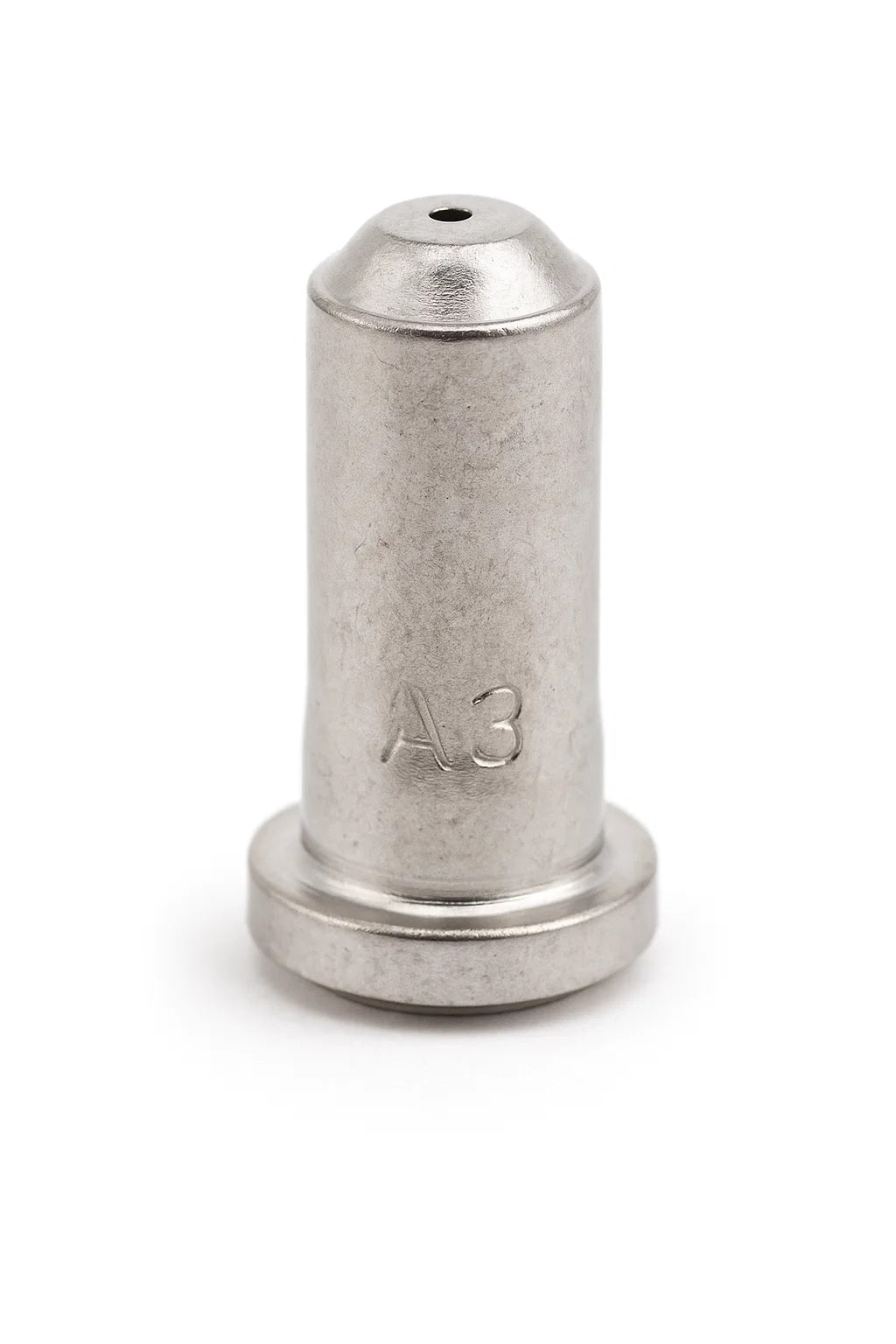
    The ESAB Model 33368 30 Amp Nozzle for Plasmarc PT-27 Plasma Torch, Pack of (5) is a consumable part used in plasma cutting. For buyers, maintenance teams, and welding support staff, the main question is not whether it is a replacement part, but whether it matches the torch family, amperage range, and cut duty you actually run on the shop floor. This draft stays focused on that practical check.

    The product page indicates this is a 30 amp nozzle intended for PT-23 and PT-27 Plasmarc plasma torches. Beyond that, the important technical details that affect fit and performance should be verified against the machine manual and the torch consumable chart before purchase or installation. If a detail is not confirmed in the source material, treat it as Unknown (Verify).

    Key Takeaways

    • This is a plasma nozzle consumable, not a universal part.
    • The listed amperage is 30 amp, but the correct operating range still needs verification against your torch and power source.
    • The source product information states PT-23 and PT-27 Plasmarc torch use.
    • As with any nozzle, cut quality depends on air quality, arc start condition, standoff, and wear state.
    • Pack quantity is five nozzles according to the source product listing.

    What This Part Does

    A plasma nozzle constricts and directs the plasma arc. In practical terms, it affects kerf shape, arc concentration, and edge quality. A worn nozzle can show up as wider kerf, rougher edge, harder starts, arc instability, or accelerated wear in related consumables. If your cut quality has changed, do not assume the nozzle is the only cause. Air contamination, electrode wear, damaged swirl components, incorrect stand-off, and double arcing can produce similar symptoms.

    For broader root-cause checks, see the support article on plasma torch nozzle damage causes. For torch-family and consumable matching logic, the plasma drag shield compatibility guide is a useful reference point, even though this part is a nozzle and not a drag shield.

    Buyer Checklist Before Ordering

    Use this as a field check before you place the order or pull stock for a job:

    • Check torch family: Confirm the torch is PT-23 or PT-27 as listed in the source product information.
    • Check amperage: Confirm your application uses a 30 amp nozzle. If the machine is set up differently, the correct match is Unknown (Verify) until confirmed.
    • Inspect the current nozzle: Look for orifice distortion, spatter buildup, ovality, or heat damage.
    • Inspect related parts: Check electrode, retaining cap, swirl ring or equivalent torch components, and air passages as applicable to your torch design.
    • Verify cut problem symptoms: If the issue is intermittent arc transfer, poor start consistency, or excessive dross, confirm whether consumable wear is actually the cause.
    • Verify machine settings: Confirm air pressure, cutting speed, stand-off, and polarity per the equipment manual. Unknown (Verify) if manual data is not on hand.

    Support and Troubleshooting Notes

    When a nozzle is replaced too early, the real problem usually stays in the system. Use a simple inspect sequence:

    1) Inspect the nozzle. Remove it and examine the orifice under good light. Check for wash-out, eccentric wear, cracks, or heavy spatter. If the opening no longer looks uniform, replacement is justified.

    2) Inspect the electrode. A damaged electrode can create arc instability that looks like nozzle failure. Replace related consumables as a set when wear is obvious or when the torch manual recommends it.

    3) Inspect air quality. Moisture, oil, and dirt in the air supply shorten consumable life. Verify dryer function, filter condition, and regulator behavior. If air quality has not been measured recently, it is Unknown (Verify).

    4) Verify torch assembly condition. Check for damaged threads, loose fit, worn retaining parts, and signs of double arcing. If the consumable stack does not seat correctly, the nozzle will not run as expected.

    5) Verify cut setup. Wrong travel speed or stand-off can destroy a new nozzle quickly. If the cut profile is poor immediately after installation, the issue may be setup rather than part quality.

    Product / Parts Section

    The source product information identifies the part as ESAB Model 33368 30 Amp Nozzle for Plasmarc PT-27 Plasma Torch, Pack of (5). The product summary also states use with PT-23 and PT-27 Plasmarc torches. No additional verified specs were provided in the source material, so any further material, dimensions, or certifications are Unknown (Verify).

    For sourcing support, the product can be reviewed through the provided ArcWeld listing: Product not found.

    “>ESAB Model 33368 30 Amp Nozzle for Plasmarc PT-27 Plasma Torch, Pack of (5). Use the listing as the product reference, then verify torch compatibility and amperage in the machine documentation before deployment.

    How to Verify Fit in the Shop

    Before issuing the part, run these checks:

    • Match the torch model: PT-23 or PT-27 per the source listing.
    • Match the consumable shape: Compare the old nozzle to the new one visually and by seating style.
    • Confirm the installation stack: Nozzle, electrode, and adjacent consumables should assemble without force.
    • Test on scrap: Make a short cut on comparable material before releasing the torch back to production.

    Safety Notes

    • De-energize the system before changing consumables.
    • Do not inspect the plasma arc directly.
    • Wear eye and hand protection during part removal and test cuts.
    • Verify compressed air condition before use. Contaminated air can shorten consumable life and affect operator safety.
    • If the torch shows repeated double arcing or abnormal noise, stop and inspect the full torch stack before continuing.

    FAQ

    Is this nozzle only for the PT-27?
    The source product information also states PT-23 compatibility. Verify the actual torch model and consumable chart before ordering.

    Can I use this nozzle at amperage other than 30 amp?
    The listing identifies it as a 30 amp nozzle. Other amperage use is Unknown (Verify) unless confirmed by the torch and power source documentation.

    What causes a new nozzle to fail quickly?
    Common causes include poor air quality, incorrect stand-off, damaged electrode parts, double arcing, and cutting too fast or too slow. Check the full system, not just the nozzle.

    Should I replace only the nozzle?
    Not always. If the electrode or other consumables are also worn, replace the worn set as a group according to the torch manual.

    Sources Checked

    • ArcWeld product listing: ESAB Model 33368 30 Amp Nozzle for Plasmarc PT-27 Plasma Torch, Pack of (5)
    • Internal support article: Plasma Torch Nozzle Damage Causes: Orifice Wear, Double Arcing, Piercing, and Air Problems
    • Internal support article: Plasma Drag Shield Compatibility Guide: Torch Family, Amperage, Nozzle, Retaining Cap, and Cut Mode Checks

    Final note: treat this part as a consumable matched to a specific torch system. Verify torch model, amperage, and assembly details before purchase and before installation. If any technical detail is not confirmed by source material or machine documentation, mark it Unknown (Verify).

    Related Arc Weld Part

    ESAB Model 33368 30 Amp Nozzle for Plasmarc PT-27 Plasma Torch, Pack of (5)

    ESAB Model 33368 30 Amp Nozzle for Plasmarc PT-27 Plasma Torch, Pack of (5)

    ESAB 33368 – 30 Amp Plasma Nozzle for Plasmarc PT-27 Torch (5-Pack) The ESAB 33368 is a 30 amp nozzle designed for use with PT-23 and PT-27 Plasmarc plasma torches. Engineered for clean, efficient cuts in light to medium-gauge metal, this nozzle delivers consistent arc stability and cut quality. Each pack contains five OEM-grade nozzles, ensuring reliable performance and compatibility with ESAB plasma systems. Spe…

    View at Arc Weld Store

    Related Weld Support Guides

  • CGW Abrasive 42554, Flap Disc 5″ x 5/8-11″ 60 Grit Zirconia, Pack of (10): Product Breakdown

    CGW Abrasive 42554, Flap Disc 5″ x 5/8-11″ 60 Grit Zirconia, Pack of (10): Product Breakdown

    Product not found.
    “>CGW Abrasive 42554, Flap Disc 5" x 5/8-11" 60 Grit Zirconia, Pack of (10)

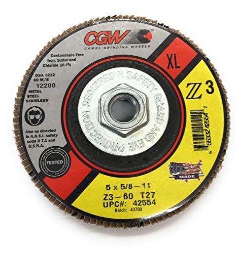
    CGW Abrasive 42554 is a 5-inch flap disc with a 5/8-11 threaded mount and 60 grit zirconia abrasive, sold as a pack of 10. For maintenance buyers and shop users, the value question is simple: does the disc match the grinder, the work material, and the expected removal rate? This breakdown stays at the selection and use level. It does not assume a specific base metal, procedure, or certification that was not provided.

    Key Takeaways

    What the Product Is

    The listed product is a CGW Abrasive flap disc, part number 42554, in a 5-inch diameter, 60 grit zirconia configuration with a 5/8-11 attachment. The source data identifies it as a pack of 10. Beyond that, exact disc build details such as backing material, exact wheel type designation, maximum RPM, and certification status are Unknown (Verify) from the provided source set.

    For buyers, that means the first job is not purchase approval. The first job is fit-up verification: confirm tool interface, confirm operating speed range from the product page or packaging, and confirm the disc is intended for the job at hand.

    Practical Use Check

    Before the disc is assigned to production, run a basic check:

    1. Inspect the threaded mount. Verify the grinder spindle is 5/8-11 and the disc threads engage cleanly by hand. Do not force cross-threaded installation.
    2. Inspect the abrasive face. Check for cracked flaps, loose edges, torn backing, contamination, or shipping damage.
    3. Verify the task. 60 grit is a removal-oriented choice. If the job requires a finer finish, confirm whether a different grit is more appropriate.
    4. Verify operator technique. Use light-to-moderate pressure only as the tool and material allow. Excessive force shortens disc life and can raise heat.
    5. Verify speed and guard compliance. Confirm the grinder is within the disc and tool limits shown by the manufacturer. If that data is not available from the source page, it remains Unknown (Verify).

    Troubleshooting and Support Checks

    If performance is not meeting expectations, work through the following checks before switching brands or assuming a product defect.

    1) Disc wears too fast

    2) Disc runs hot

    3) Material removal is uneven

    4) Threaded mount does not seat correctly

    Product and Parts Section

    Product: CGW Abrasive 42554, Flap Disc 5" x 5/8-11" 60 Grit Zirconia, Pack of (10)

    Source description: The provided source states premium zirconia, aggressive stock removal, smooth finishing, strong edge stability, and cool cutting with light pressure. Those are manufacturer-level claims from the provided product source. Independent verification of exact test data is not available in the supplied materials.

    Buyer note: If your shop standardizes by grinder platform, verify that this 5/8-11 mount is the correct interface for your fleet. If your fleet uses a different attachment style, this product may not be a direct replacement.

    For comparison context, related flap disc content on Weld Support Parts includes other CGW, Norton, and Weldcote examples with different diameters, grits, and mount styles. Use those as internal reference points only, not as compatibility proof for this item.

    Selection Guidance

    Use this disc when the job needs steady removal and controlled blending rather than a finish-only pass. If the application is light finishing, a finer grit may be more appropriate. If the application is heavy scale removal, a more aggressive setup may be required. Exact material matching is Unknown (Verify) because the supplied source does not define target metals or approved applications.

    For maintenance buyers, the pack of 10 can reduce reorder frequency, but only if the shop actually consumes this grit and mount style at a steady rate. Check burn rate on the floor before putting it on blanket issue.

    Safety Notes

    FAQ

    Is CGW Abrasive 42554 a finishing disc or a removal disc?

    It is best treated as a removal-oriented flap disc with 60 grit abrasive. It can blend surfaces, but it is not a final-finish product.

    Will it fit every 5-inch grinder?

    No. The product uses a 5/8-11 threaded mount, so fit depends on the grinder spindle. Verify the spindle thread before purchase or issue.

    Can it be used on all metals?

    That is not confirmed by the provided source. Material-specific compatibility is Unknown (Verify). Confirm the base metal and the shop’s abrasive practice before use.

    What should buyers confirm before stocking it?

    Confirm mount style, grinder interface, grit level, expected consumption rate, and any internal safety or job-specific requirements. Also verify the exact product data on the source page or package label.

    Sources Checked

    Related Arc Weld Part

    CGW Abrasive 42554, Flap Disc 5" x 5/8-11" 60 Grit Zirconia, Pack of (10)

    CGW Abrasive 42554, Flap Disc 5" x 5/8-11" 60 Grit Zirconia, Pack of (10)

    CGW Abrasives 42554 Flap Disc – 5" x 5/8-11", 60 Grit Zirconia (Pack of 10) Maximize cutting efficiency and durability with the CGW Abrasives 42554 Flap Disc, designed for aggressive stock removal and smooth finishing. Featuring premium 100% zirconia, this flap disc offers maximum cutting capacity, strong edge stability, and cool cutting with light pressure, ensuring long-lasting performance. Ideal for heavy-duty…

    View at Arc Weld Store

    Related Weld Support Guides

  • Hobart AirForce 27i Plasma Cutter Support: Parts Lookup and Buying Checks

    Hobart AirForce 27i Plasma Cutter Support: Parts Lookup and Buying Checks

    Hobart AirForce 27i Plasma Cutter Support

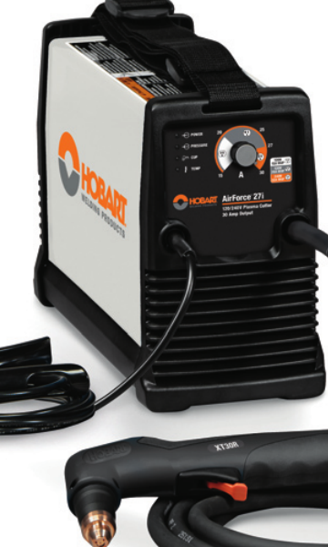
    If you maintain a Hobart AirForce 27i, the fastest way to avoid wrong-parts orders is to verify the machine identifier, torch family, power input, and air-side support items before you buy. The AirForce 27i support page from Weld Support Parts is set up as a lookup starting point for those checks. It lists the unit support page, the stock reference 500575, 120/240 V information, an XT30R replacement torch reference, consumables, MVP adapters, an air filter kit, cutting guides, and plasma support links.

    Key Takeaways

    • Use the support page to confirm the AirForce 27i parts path before ordering.
    • Verify torch model, consumable style, and power input at the machine nameplate and on the existing torch.
    • Air quality matters. Inspect the air filter path before troubleshooting arc problems.
    • Do not assume adapter or torch compatibility from appearance alone.
    • When details are unclear, mark them as Unknown (Verify) and confirm against the machine and torch labels.

    What the Support Page Is Useful For

    The Weld Support Parts AirForce 27i page is a parts lookup and support reference, not a substitute for the machine manual. It is useful when you need to match the cutter to support items such as the replacement torch, consumables, and air-side accessories. For this model, the page references stock 500575 and indicates 120/240 V support information. Treat those details as lookup cues and verify them on the machine before purchasing or installing parts.

    Open the Hobart AirForce 27i support page

    Buying Checks Before You Order Parts

    Before a maintenance buyer releases an order, do these checks in order:

    1. Check the machine data plate. Verify the exact model is Hobart AirForce 27i and confirm input power requirements. If the plate is unclear, record Unknown (Verify).
    2. Inspect the torch neck and handle label. Confirm whether the installed torch matches the XT30R family reference shown on the support page. Do not assume the torch is original.
    3. Pull the consumable set and compare wear patterns. Look at the nozzle, electrode, swirl ring, shield, and retaining parts. Replace only with the correct style for the torch in use.
    4. Check the air delivery path. Inspect filters, fittings, hoses, and water or oil contamination. A plasma cutter with poor air quality will often show unstable arc behavior.
    5. Confirm adapter needs. If the shop uses an alternate power plug or input arrangement, check whether the MVP adapter reference is relevant to your setup. Compatibility details not shown on the support page should stay Unknown (Verify).

    Troubleshooting and Support Checks

    Use these checks when the cutter starts to misbehave or when you are deciding which support part to buy.

    1) Torch and Consumable Check

    • Inspect: Look for heat damage, cracked cups, eroded electrodes, and loose retaining parts.
    • Verify: Match the torch consumables to the actual torch family on the machine. If the torch label is unreadable, mark the torch type Unknown (Verify) until confirmed.
    • Replace: Only the parts that are visibly worn or listed for the identified torch family.

    2) Air Supply Check

    • Inspect: Air filter kit condition, bowl contamination, hose leaks, and regulator settings.
    • Verify: The shop air is dry and clean enough for plasma use. If you see oil, water, or heavy debris, correct that before blaming the torch.
    • Check: Flow remains stable during trigger pull. A pressure drop can mimic a bad torch or bad consumable.

    3) Power and Input Check

    • Inspect: Input cord, plugs, adapters, and receptacle condition.
    • Verify: The machine is connected to the correct input class shown for the AirForce 27i support reference. If the exact electrical setup is not confirmed, note it Unknown (Verify).
    • Check: Any adapter or extension is rated and approved for the actual jobsite setup. Do not use an adapter just because the plug shape fits.

    4) Cut Quality Check

    • Inspect: Edge squareness, dross, and arc consistency.
    • Verify: The torch is held at a consistent standoff and travel speed.
    • Check: The cut guide or drag shield is appropriate for the work method you are using.

    WSP Lookup Page Notes

    The AirForce 27i support page is the correct first stop when you need a parts and support overview for this machine. It identifies the machine support page, stock 500575, the XT30R replacement torch reference, consumables, MVP adapters, air filter kit, cutting guides, and other plasma support links. Use those references to narrow the search, then confirm exact fitment against the machine and torch markings.

    Important: This page is a selection aid, not a blanket approval for every installed torch or accessory. If the part family is not confirmed from labels or existing component markings, the correct status is Unknown (Verify).

    Go to the Hobart AirForce 27i support page

    Practical Inspection Routine for Shops

    For routine maintenance, use a short inspection routine before each parts order or service ticket:

    • Record the machine model and serial tag information.
    • Compare torch markings to the support page reference.
    • Pull the last installed consumables and note wear pattern.
    • Inspect air filters and moisture traps.
    • Check the power plug, adapters, and cord strain relief.
    • Confirm any cutting guides or accessories are intended for the actual torch setup.

    Safety Notes

    • De-energize the machine before inspecting internal or electrical components.
    • Bleed pressure from the air system before opening filters or fittings.
    • Do not touch hot consumables immediately after cutting.
    • Use eye, hand, and body protection suitable for plasma cutting and grinding cleanup.
    • Do not bypass safety devices or use unverified adapters in an attempt to make a part fit.

    FAQ

    Is the XT30R replacement torch definitely the correct torch for every AirForce 27i?

    No. The support page references XT30R as a replacement torch reference, but you should still verify the torch family on the machine and existing torch. If the installed torch is not confirmed, mark it Unknown (Verify).

    Can I order consumables just by machine model?

    Not safely. Consumables must match the actual torch family and installed setup. Start with the AirForce 27i support page, then verify the torch label and worn parts before ordering.

    What should I check first if the cutter will not make a stable arc?

    Start with the consumables and the air supply. Inspect electrode and nozzle wear, then verify that air is clean, dry, and steady. If those checks are inconclusive, move to power input and torch condition.

    Are the MVP adapters universal?

    Do not assume that. The support page lists MVP adapters as a support reference, but any actual compatibility must be confirmed against the machine and power setup. If it is not confirmed, use Unknown (Verify).

    Sources Checked

    For maintenance teams, the key is simple: verify the machine, verify the torch, verify the air, then buy the parts that match what is actually installed. That is the cleanest way to support a Hobart AirForce 27i without creating avoidable returns or downtime.

    Disclosure: As an Amazon Associate, Weld Support Parts may earn from qualifying purchases.

    Related Weld Support Guides

  • Hypertherm 851462 Powermax30 AIR Essential Consumable Kit: Replacement Part Breakdown

    The Hypertherm 851462 Powermax30 AIR Essential Consumable Kit is a replacement-part purchase, not a process-change item. Buyers usually need it to keep a handheld plasma system ready for service, reduce downtime, and restore cut quality after normal wear. For support teams and maintenance buyers, the practical question is simple: what is included, what wears first, and what should be checked before the kit is installed?

    This guide focuses on part-level verification and field-use checks. It does not assume any unlisted compatibility beyond the product name provided. If you are matching a machine, torch, or cartridge configuration, verify every identifier against your system documentation before ordering or installation.

    Key Takeaways

    • This is an essential consumable kit for a Powermax30 AIR setup; treat it as wear-part support.
    • Consumables are normal replacement items. Poor cut quality is often a wear issue, not a machine failure.
    • Before use, verify torch model, retaining hardware, and electrode/nozzle condition against your current parts.
    • If the kit contents are not fully confirmed from your source listing, mark the unclear items as Unknown (Verify).
    • Do not force-fit plasma consumables. If the stack-up does not match, stop and confirm the part numbers.

    What to Check Before You Order

    For a consumable kit, the safest buying method is to confirm three points first:

    • Machine identity: confirm the exact plasma unit and torch family in service.
    • Consumable style: confirm whether your torch uses the same electrode, nozzle, shield, and retaining arrangement as the kit you are sourcing.
    • Wear pattern: inspect your current parts and compare the wear to the symptoms on the floor.

    Check: Look for arc instability, rough edge quality, excessive dross, or difficulty transferring arc. These are common reasons crews replace consumables early.

    Inspect: Remove the current tip stack and inspect for pitting, distortion, heat damage, or gas-flow contamination. Examine the torch body for damage that would shorten consumable life.

    Verify: Match the replacement parts to the exact service documents or parts diagram for your setup. If a component cannot be confirmed from the source listing, list it as Unknown (Verify).

    Replacement-Part Breakdown

    The product is identified as an essential consumable kit. That means the useful breakdown is functional, not speculative. In plasma service, the common wear components are typically the electrode, nozzle, shield or deflector, and retaining components. However, the exact contents of this kit should be confirmed from the source listing or packaging.

    • Electrode: Carries the arc load and is a primary wear item.
    • Nozzle: Shapes the arc and affects cut quality and kerf consistency.
    • Shield/deflector: Helps protect the torch and can influence cut standoff behavior.
    • Retaining hardware: Holds the consumable stack in position. Any damage or thread wear can affect retention.

    If the kit contents are not explicitly confirmed by your purchase source, do not assume the stack includes every item above. Mark unknown contents as Unknown (Verify) and cross-check the carton or listing before dispatching it to the field.

    Troubleshooting and Support Checks

    When a plasma cutter starts cutting poorly, do not jump straight to machine repair. Consumables are the first inspection point.

    Check: Inspect the nozzle orifice for enlargement, oval wear, or spatter contamination.

    Inspect: Examine the electrode face for a deep pit or uneven erosion.

    Verify: Confirm that the shield and retaining parts are not cracked, cross-threaded, or seated incorrectly.

    Check: If the arc starts but cuts are inconsistent, verify air quality, line pressure at the machine, and the condition of the consumable stack.

    Inspect: Look for moisture, oil, or debris in the air line and filter path. Contaminated air shortens consumable life.

    Verify: Make sure the torch is assembled in the correct order. A mis-stacked consumable set can create the same symptoms as a worn part.

    Check: If you see repeated consumable burn-back, inspect duty cycle and operating technique.

    Inspect: Review cut travel speed, pierce height, and standoff consistency.

    Verify: Confirm that the operator is using the correct technique for the workpiece thickness and edge condition.

    Product and Parts Section

    Product referenced: Hypertherm 851462 Powermax30 AIR Essential Consumable Kit

    ASIN: B01CSBV3FE

    Amazon affiliate product reference:

    No products found.

    Use this product as a replacement consumable source only. Do not assume it changes the procedure, the duty cycle, or the machine configuration. If your maintenance program requires serialized parts control, record the kit identification and the installation date when the parts are issued.

    Part verification step:

    1. Confirm the machine and torch model in service.
    2. Open the existing consumable stack and compare wear against the replacement parts.
    3. Verify that each part matches the required stack order.
    4. Install only after fit and seating are confirmed.
    5. Test cut on approved scrap material before returning the unit to production.

    Safety Notes

    • De-energize the system before service.
    • Allow hot parts to cool before handling.
    • Wear eye protection and gloves during inspection and replacement.
    • Do not touch electrode or nozzle surfaces with bare hands if contamination control is required by your shop practice.
    • Use approved torch and machine procedures only. Unknown (Verify) settings should not be guessed in the field.

    FAQ

    Q: Is this kit for routine maintenance or repair?
    A: Routine maintenance. Consumables are wear parts and are replaced as performance declines.

    Q: Can I assume the kit fits every Powermax30 system?
    A: No. Verify the exact machine and torch configuration before ordering. Compatibility details not confirmed in the source should be treated as Unknown (Verify).

    Q: What causes consumables to wear out early?
    A: Common causes include poor air quality, incorrect cut technique, excessive pierce abuse, and contaminated or damaged torch components.

    Q: What should I do if the replacement parts do not match my existing stack?
    A: Stop and verify the part numbers against the machine manual, torch diagram, or current packaging before installation.

    Sources Checked

    Note: No raw Amazon URL was used. Any unconfirmed content details remain Unknown (Verify).

    Disclosure: As an Amazon Associate, Weld Support Parts may earn from qualifying purchases.

    Related Weld Support Guides

  • Miller 263349, Tig Welding Gloves, X-Large, White/Blue, Pack of (1 Pair): Replacement Part Breakdown

    Miller 263349 TIG welding gloves are a personal protection item, so the support question is usually not repair in the field but fit, condition, and replacement timing. For maintenance buyers and welding teams, the useful breakdown is simple: confirm the glove is the correct size, inspect for damage before issue, verify the glove matches the task, and replace it when wear starts to affect dexterity or protection. The product in this draft is the Amazon-registry item identified by ASIN B00HES3RJM. No extra compatibility claims should be assumed beyond the product listing itself.

    Key Takeaways

    • This is a TIG glove for hand protection during welding work, not a consumable weld process part.
    • Size matters. X-Large only helps if the user can grip torch controls, filler rod, and part fixtures without excess looseness.
    • Before issue, inspect for holes, open seams, heat damage, stiffened leather, contamination, and reduced dexterity.
    • When uncertain about material details, heat resistance, or seam construction, mark them as Unknown (Verify) rather than assume.
    • For plant support, the practical job is accept, inspect, issue, and replace; do not try to modify a worn glove into service.

    What to Check Before You Issue the Gloves

    Start with a receiving inspection. Compare the shipped item to the purchase record and confirm the product name and ASIN match the order. Then verify the pair is complete and that each glove is the same general condition. If the packaging, sizing, or markings are unclear, treat those details as Unknown (Verify) until confirmed by the supplier listing or internal receiving record.

    Inspect

    • Check both gloves for cuts, burn marks, abrasion, oil saturation, or stitching failures.
    • Inspect finger tips, thumb crotch, palm, and cuff areas first. Those are the highest-wear points in TIG work.
    • Flex the glove by hand. If the material feels rigid or cracks when bent, it may be past serviceable condition.
    • Look for stitching gaps at the seams. A small seam opening can grow quickly with repeated torch manipulation.

    Verify

    • Verify the glove size allows a secure torch grip without cutting off circulation.
    • Verify the glove does not interfere with trigger access, torch angle control, or filler rod handling.
    • Verify the glove is clean enough for the work area. Contamination from oil or chemicals can reduce grip and may increase fire risk.

    Replacement-Part Breakdown for Support Teams

    There are no user-replaceable internal parts in a welding glove set. If a glove fails, the replacement path is typically full pair replacement, not patching. For maintenance buyers, track these as PPE stock items instead of repair parts. If your team uses a glove issue log, record the failure mode: seam failure, abrasion, heat exposure, contamination, fit issue, or general wear. That helps you spot whether the problem is product life, task mismatch, or handling practices.

    If the question is whether this specific glove should be used for a certain process, the answer depends on your site rule, job hazard analysis, and the supplier’s product details. Unknown (Verify) is the correct answer for any feature not shown in the source listing. Do not assume the glove is approved for all TIG applications, overhead work, or extended heat exposure.

    Support Troubleshooting: Common Issues

    Issue: Gloves feel too loose

    • Check: Does the glove shift when holding the torch?
    • Inspect: Are the fingertips collapsing or folding at the grip point?
    • Verify: Does the user need a different size or glove style for control?

    Issue: Gloves feel too tight

    • Check: Can the user fully close the hand and flex the fingers?
    • Inspect: Look for seam stress at the knuckles and thumb area after a short trial fit.
    • Verify: Confirm the issue is size, not swelling, improper hand position, or a work technique problem.

    Issue: Premature wear in service

    • Check: Is the glove being used on sharp edges, hot metal, or rough handling tasks beyond TIG support?
    • Inspect: Review the wear pattern. Localized damage usually points to process contact, not a manufacturing defect.
    • Verify: Match the glove to the task and move rough handling to a different glove type if needed.

    Product and Parts Notes

    The product identified here is Miller 263349, TIG welding gloves, X-Large, White/Blue, pack of one pair, ASIN B00HES3RJM. Beyond that product identity, detailed technical attributes should not be inferred unless they are stated in the source listing you are using for procurement. If your purchasing team needs exact material, seam, cuff, or lining details, record those items as Unknown (Verify) and confirm them before standardizing the glove across a department.

    Because this is PPE, the most useful “parts” decision is not component replacement. It is whether the glove still passes your inspection standard. If not, replace the entire pair.

    Safety Notes

    • Do not use damaged gloves in welding or hot work.
    • Do not assume a glove is suitable for every TIG task because it is labeled for TIG welding.
    • Keep gloves free of oil, solvents, and other contaminants that can affect grip and performance.
    • Follow site PPE rules, hot work permits, and task-specific hazard controls.

    FAQ

    Is this glove repairable?

    In normal shop use, no. PPE gloves are usually replaced when seams, palm areas, fingertips, or cuffs are damaged. Small field repairs should not be treated as a return to full service unless your site procedure allows it and the glove still passes inspection.

    How do I know when to replace it?

    Replace it when you find holes, seam failures, heat damage, hardening, contamination that cannot be cleaned out, or loss of dexterity. If the glove no longer allows controlled torch handling, it is no longer doing its job.

    Does X-Large mean it will fit every user with large hands?

    No. Sizing is individual. Verify fit by checking hand closure, grip control, and cuff comfort during an actual task movement, not just a static try-on.

    Can I use this glove for non-welding work?

    Only if your site rules allow it and the glove condition is suitable for the job. Do not assume it is appropriate for sharp-edge handling, chemical exposure, or general-purpose impact work.

    Sources Checked

    • Provided Amazon registry product reference: ASIN B00HES3RJM
    • Provided product name: Miller 263349, Tig Welding Gloves, X-Large, White/Blue, Pack of (1 Pair)

    No WSP lookup page, filler metal finder page, or internal links were provided for this draft.

    Matched Replacement Option

    No products found.

    Disclosure: As an Amazon Associate, Weld Support Parts may earn from qualifying purchases.

  • Listen with Audible