Undercut in stick welding appears as a groove melted into the base metal along the weld toe that is not filled properly by weld metal. It is commonly caused by excessive amperage, incorrect rod angle, excessive travel speed, poor weave control, or improper electrode manipulation. Undercut weakens weld strength, creates stress concentration points, and can cause weld rejection on structural and code work.
Common Symptoms
Visible groove along the weld toe.
Sharp edge transitions beside the weld bead.
Weld bead appears narrow or rope-like.
Undercut worsens near restarts or weave edges.
Grinding reveals reduced weld toe thickness.
Excessive spatter and aggressive arc behavior.
Likely Causes
Amperage too high: Excess heat melts the base metal faster than filler metal can refill the edges.
Travel speed too fast: Rapid movement prevents the puddle from filling the weld toes completely.
Incorrect rod angle: Excessive drag or push angle concentrates heat on one edge.
Excessive weave width: Wide weaving cools the puddle unevenly and leaves the edges underfilled.
Arc length too long: Long arcs create unstable puddles and aggressive sidewall washout.
Poor pause timing: Insufficient pause at weave edges prevents toe fill.
Inspection Steps
Inspect both weld toes for grooves or sharp edge transitions.
Verify amperage settings match the electrode size and position.
Check rod angle during welding.
Review travel speed and weave width.
Inspect restarts for localized undercut.
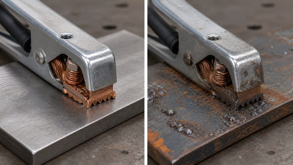
Inspect work clamp connection and arc stability.
Verify electrode condition and storage.
Visual Wear Indicators
Sharp grooves along weld edges.
Thin weld toes.
Overly convex or narrow bead profile.
Irregular weave spacing.
Excessive sidewall washout.
Common Wrong-Part Mistakes
Using oversized electrodes on thin material.
Running low-hydrogen rods at excessive amperage.
Using the wrong polarity for the electrode type.
Trying to cover undercut with additional cold passes instead of grinding and repairing properly.
Field Fix vs Proper Fix
Field fix: Lower amperage slightly, shorten arc length, slow travel speed, and pause briefly at weave edges. Proper fix: Grind out severe undercut, correct the welding procedure, improve rod manipulation technique, and match electrode size to the joint geometry and material thickness.
Related Failure Paths
Slag inclusion
Lack of fusion
Toe cracking
Porosity
Cold lap
Safety Notes
Grinding out undercut creates sparks, debris, and airborne particles. Use proper eye protection, gloves, hearing protection, and ventilation during weld repair and cleanup operations.
Excessive slag inclusion in stick welding usually comes from poor slag removal, incorrect rod angle, low amperage, improper travel speed, restarting over trapped slag, or poor joint preparation. Slag inclusions occur when nonmetallic flux residue becomes trapped inside the weld instead of floating to the surface. This weakens weld integrity, reduces fusion quality, and can cause weld rejection on structural or code work.
Common Symptoms
Dark lines or pockets visible inside the weld.
Slag trapped between weld passes.
Incomplete fusion near the weld toes.
Weld cracking along slag pockets.
Rough bead appearance with uneven slag release.
Grinding reveals trapped glassy material inside the weld.
Likely Causes
Incomplete slag removal: Previous pass slag must be fully chipped and brushed before rewelding.
Low amperage: Insufficient heat prevents slag from floating properly behind the puddle.
Incorrect rod angle: Excessive drag angle can push slag ahead of the weld puddle.
Travel speed too fast: Rapid movement traps slag before it can rise out of the puddle.
Weaving too wide: Excessive weave width can cool the puddle unevenly and trap slag at the toes.
Inspection Steps
Inspect weld passes for trapped slag lines or uneven bead edges.
Chip and wire brush aggressively between all passes.
Verify amperage settings for the rod diameter being used.
Inspect rod storage conditions and electrode condition.
Check weld joint geometry for proper slag escape.
Inspect restart areas for trapped crater slag.
Review rod angle and travel speed during welding.
Visual Wear Indicators
Slag trapped at weld toes.
Glassy pockets revealed during grinding.
Irregular slag peeling patterns.
Cold lap appearance near weld edges.
Dark inclusion lines inside multi-pass welds.
Common Wrong-Part Mistakes
Using low-hydrogen rods that were improperly stored.
Running incorrect polarity for the electrode type.
Using oversized electrodes on tight joints.
Trying to bury slag inclusions under additional weld passes.
Field Fix vs Proper Fix
Field fix: Increase amperage slightly, reduce travel speed, and clean between passes more aggressively. Proper fix: Grind out slag inclusions completely, correct joint preparation, improve restart technique, and verify the welding procedure matches the electrode type and position.
Related Failure Paths
Undercut
Lack of fusion
Porosity
Restart cracking
Cold lap
Safety Notes
Grinding and slag removal produce sharp debris and airborne particles. Use face shields, safety glasses, gloves, and proper ventilation during weld cleanup and inspection.
Push-pull gun wire feeding problems are usually caused by liner drag, incorrect drive roll tension, poor feeder synchronization, worn contact tips, cable routing issues, spool drag, or damaged gun motors. Push-pull systems are designed to stabilize soft wire feeding, especially aluminum, but even small setup problems can create severe feeding instability, burnback, birdnesting, and inconsistent arc performance.
Common Symptoms
Wire feed surges or hesitates during welding.
Birdnesting near the feeder or gun.
Erratic aluminum arc starts.
Burnback into the contact tip.
Drive rolls slip during feeding.
Motor strain or overheating during longer welds.
Wire feeding changes when the cable bends.
Likely Causes
Incorrect drive roll tension: Excess pressure deforms soft aluminum wire while low pressure causes slippage.
Contaminated or damaged liner: Aluminum debris and dirt increase feed resistance quickly.
Improper spool brake tension: Excess drag overloads the push-pull system.
Poor cable routing: Tight bends increase friction and feeding instability.
Worn contact tips: Enlarged or damaged tips destabilize current transfer and feeding consistency.
Feeder synchronization problems: Push and pull motor speeds must remain balanced.
Incorrect drive roll type: Wrong groove geometry damages soft wire.
Inspection Steps
Inspect drive rolls for wear and correct groove style.
Check spool brake tension for smooth rotation.
Inspect the liner for contamination or crushed sections.
Verify cable routing does not include severe bends.
Inspect contact tips for wear or aluminum buildup.
Check work clamp contact on clean bare metal.
Test wire-feed consistency while flexing the cable gently.
Visual Wear Indicators
Shaved aluminum wire particles near the feeder.
Birdnesting at drive rolls.
Dark heat discoloration on contact tips.
Wire flattening from excessive roll pressure.
Erratic spool acceleration or stopping.
Common Wrong-Part Mistakes
Using steel drive rolls for aluminum wire.
Installing incorrect liner materials.
Running worn contact tips too long.
Using incompatible push-pull gun control harnesses.
Field Fix vs Proper Fix
Field fix: Reduce drive roll pressure, clean the liner, improve cable routing, and replace worn contact tips. Proper fix: Correct feeder synchronization, replace damaged motors or liners, verify gun compatibility, and match the full wire-feed system to the aluminum wire size and application.
Related Failure Paths
Burnback
Birdnesting
Motor overheating
Trigger delay
Erratic aluminum arc starts
Safety Notes
Disconnect power before servicing push-pull feeders, drive rolls, or gun motors. Feeding systems contain moving drive components that can pinch fingers or damage wire unexpectedly during testing.
Sources Checked
Lincoln Electric MIG equipment catalogs
Lincoln accessories catalog
Uploaded consumables and aluminum welding references
Handheld Laser Welding vs MIG for Sheet Metal Repair: Where Each Process Fails
Handheld laser welding is rapidly gaining attention for thin-gauge fabrication, stainless repair, HVAC work, and cosmetic welding because it can produce narrow welds with lower heat input and minimal post-cleaning. MIG welding still remains the more forgiving process for field repair, poor fit-up conditions, contaminated metal, outdoor welding, and structural fabrication.
The biggest mistake shops make when comparing handheld laser welding to MIG is assuming laser welding is simply a faster replacement for wire welding. In reality, the two processes fail differently. Laser welding is far less tolerant of gaps, edge mismatch, reflective contamination, unstable shielding gas coverage, dirty surfaces, and poor joint preparation. MIG is slower and creates more heat distortion, but it usually handles repair conditions better when parts are imperfect.
Where Handheld Laser Welding Performs Best
Thin stainless fabrication
Sheet metal assemblies with tight fit-up
Cosmetic visible welds
Low-distortion repair work
HVAC and light manufacturing
Repeatable production welding
Modern handheld laser systems can produce significantly faster travel speeds than TIG welding with reduced post-processing requirements. Systems like the Miller OptX handheld laser platform also include preset parameters and integrated wire-feed capability for production-oriented applications.
Why Laser Welding Fails on Poor Fit-Up
Fit-up tolerance is one of the biggest differences between handheld laser welding and MIG welding.
MIG can bridge moderate gaps because filler deposition is relatively forgiving
Laser welding depends heavily on precise edge alignment
Gap variation destabilizes penetration consistency
Excessive gaps can create underfill, lack of fusion, or burn-through
Laser welding usually performs best when parts are tightly fitted with consistent edge preparation. Rust scale, warped sheet metal, uneven flange alignment, and damaged edges often create immediate process instability.
Gap Tolerance: MIG vs Handheld Laser
Condition
MIG Welding
Handheld Laser
Poor edge fit-up
Usually manageable
Often problematic
Dirty steel
More forgiving
Requires cleaner surface
Outdoor welding
Possible with precautions
More sensitive to environmental conditions
Thin gauge distortion
Higher risk
Lower heat input
Visible cosmetic welds
Requires cleanup
Often cleaner appearance
Structural gap filling
Better suited
Limited tolerance
Reflective Metals and Laser Instability
Reflective materials such as aluminum, polished stainless, copper alloys, and galvanized surfaces can create instability during laser welding.
Surface reflectivity affects beam absorption
Contamination changes penetration behavior
Inconsistent prep creates weld variation
Highly reflective surfaces may require different parameter tuning
MIG welding is generally more tolerant of inconsistent surface reflectivity, although contamination can still create porosity and instability.
Shielding Gas Requirements
Shielding gas selection matters significantly in both processes, but handheld laser systems can become unstable much faster if gas flow is incorrect.
The Miller OptX platform specifies argon and nitrogen process gases depending on the application. Incorrect shielding gas flow, nozzle contamination, or turbulence can quickly affect weld consistency and surface quality.
MIG welding generally tolerates small shielding inconsistencies better, especially during repair work.
Heat-Affected Zone Comparison
One major advantage of handheld laser welding is reduced heat input.
Smaller heat-affected zones
Reduced panel distortion
Less grinding and finishing
Lower visible discoloration on stainless
MIG welding remains more practical for thicker repair work, larger gaps, and inconsistent joint conditions where deposition volume matters more than minimal heat input.
Consumable Cost Differences
MIG systems typically use inexpensive consumables with broad availability:
Contact tips
Nozzles
Diffusers
Drive rolls
Liners
Handheld laser systems often involve higher replacement costs for optics protection components, specialty nozzles, cleaning consumables, and system maintenance parts.
Laser systems also introduce downtime considerations that many repair shops underestimate.
The Learning Curve Myth
Some handheld laser marketing claims the process is easier than MIG or TIG welding. While laser welding may simplify travel consistency and cosmetic appearance on properly prepared material, successful operation still requires process discipline.
Joint preparation matters more
Fit-up consistency becomes critical
Safety requirements increase significantly
Operators still need welding knowledge
Parameter selection still affects penetration and fusion quality
Repairability in Field Conditions
MIG welding remains the better process for many field repair environments.
Better tolerance for dirty or painted material
More forgiving outdoors
Easier generator compatibility
Better for inconsistent repair joints
Less sensitive to exact edge condition
Laser systems often perform best in controlled fabrication environments with consistent power quality and clean material preparation.
Power Requirements and Shop Limitations
Many handheld laser systems require significant input power compared to compact MIG systems. The Miller OptX 2kW platform specifies 32A single-phase 240V input requirements.
Small repair shops may need electrical upgrades before installing a handheld laser system safely.
Laser Welding PPE and Safety Concerns
Handheld laser systems create different safety requirements than conventional arc welding.
Class 4 laser hazards require strict eye protection protocols
Reflective surfaces increase risk exposure
Controlled welding zones may be required
Operators and nearby personnel need proper shielding protection
Fume extraction remains important despite lower visible smoke
Laser welding should never be treated as a casual replacement for conventional welding without proper training and safety controls.
When MIG Is Still the Better Choice
Farm repair
Heavy fabrication
Outdoor repair work
Structural welding
Poor fit-up conditions
Dirty or inconsistent material
Lower-budget repair environments
Where Handheld Laser Welding Makes Sense
Thin-gauge stainless fabrication
Cosmetic weld production
HVAC manufacturing
Precision fabrication
Automated or repeatable workflows
Applications where post-processing reduction matters
Sources Checked
Miller OptX handheld laser documentation, welding safety references, fabrication process comparisons, shielding gas guidance, and practical sheet metal repair workflows were reviewed for this article.
MIG wire birdnesting is one of the most common wire feed failures in both hobby and production welding environments. The problem usually appears as tangled welding wire packed behind the drive rolls or inside the feeder area after the wire stops feeding correctly.
Birdnesting is trending heavily across welding forums, repair searches, and support communities because modern inverter MIG welders, long gun cables, soft aluminum wire, worn liners, and incorrect drive roll tension continue creating feed reliability problems.
This guide explains the most common causes of MIG birdnesting, how to diagnose the failure correctly, compatibility issues between consumables and feeder systems, and what to inspect before replacing parts.
Key Takeaways
Most birdnesting starts because wire feed resistance exceeds drive roll control.
Incorrect drive roll tension is one of the most common causes.
Oversized or damaged contact tips commonly trigger burnback and birdnesting.
Poor wire spool tension can overload the drive system.
Knurled rolls used on solid wire can deform wire and worsen feeding.
What MIG Birdnesting Looks Like
Birdnesting occurs when welding wire stops moving through the gun normally while the drive rolls continue feeding wire. The wire then collapses and tangles near the feeder assembly, creating a compact “bird nest” of wire.
This usually happens:
Behind the drive rolls
At the inlet guide
Inside the feeder housing
Near the gun connection block
Common Symptoms
Symptom
Likely Cause
Severity
Common Related Part
Wire bunches at feeder
Excessive feed resistance
High
Liner
Burnback into tip
Feed interruption
High
Contact tip
Intermittent feeding
Dirty or worn liner
Medium
MIG liner
Wire shaving
Incorrect drive rolls
Medium
Drive rolls
Feed motor slipping
Improper tension settings
Medium
Drive assembly
Aluminum wire collapsing
Push distance too long
High
MIG gun
Most Common Causes of MIG Birdnesting
1. Incorrect Drive Roll Tension
Excessive drive roll pressure crushes welding wire and increases drag inside the liner. Insufficient pressure allows slipping.
Proper tension normally allows the wire to stop against resistance without severe wire deformation.
2. Worn or Dirty MIG Liner
Liners collect metal dust, rust particles, wire shavings, and contamination over time. Increased liner resistance is one of the leading causes of feed instability.
Steel liners eventually wear grooves internally, especially with high wire volume production welding.
3. Wrong Drive Roll Type
Drive roll selection must match wire type.
Wire Type
Recommended Roll Type
Notes
Solid steel wire
V-groove
Most common MIG setup
Flux-core wire
Knurled
Improves traction
Aluminum wire
U-groove
Prevents wire deformation
Soft alloy wire
U-groove
Reduces crushing
4. Contact Tip Restrictions
Undersized, worn, or partially blocked contact tips create wire drag and feed stoppage.
Burnback often starts after wire movement slows at the contact tip.
5. Long MIG Gun Cable Length
Long gun assemblies increase wire friction. This becomes significantly worse with aluminum wire and small-diameter solid wire.
Many birdnesting issues appear after upgrading from a 10 ft gun to a 15–25 ft assembly without adjusting feeder settings.
6. Aluminum Wire Feeding
Soft aluminum wire is highly prone to collapsing under drive roll pressure. Push-only feeding systems commonly struggle with aluminum over long cable distances.
Spool guns and push-pull systems are often used specifically to reduce aluminum birdnesting problems.
Installing generic consumables without verifying fitment
Related Failure Paths
Burnback failures
Porosity from unstable arc
Drive motor overload
Excess spatter
Wire shaving contamination
Contact tip overheating
Gun neck overheating
Safety Notes
Disconnect machine power before feeder inspection.
Sharp wire ends can puncture gloves and skin.
Do not adjust drive rolls while feeding wire.
Overheated contact tips remain hot after welding stops.
Damaged liners can create erratic arc behavior.
FAQ
Why does aluminum wire birdnest more easily? Aluminum wire is softer and collapses more easily under feed pressure.
Can a dirty liner cause birdnesting? Yes. Increased drag inside the liner is one of the most common causes.
Should I increase drive roll tension to stop slipping? Excessive tension often worsens birdnesting by deforming the wire.
Do spool guns help prevent birdnesting? Yes. Spool guns reduce wire push distance and improve aluminum feed reliability.
Can incorrect contact tips cause feed issues? Yes. Undersized or damaged tips frequently create wire drag and burnback.
Next Step
Most MIG birdnesting problems can be solved by correcting liner condition, drive roll setup, wire path resistance, and consumable compatibility before replacing the entire gun assembly.
Excessive air pressure on a plasma cutter can create unstable arc behavior, poor cut quality, accelerated consumable wear, double arcing, bevel problems, and torch overheating. Many operators assume more air pressure improves cutting performance, but plasma systems are designed to operate within a specific pressure and flow range. When pressure exceeds the torch or power source specification, airflow can disrupt the plasma arc instead of stabilizing it.
Common Symptoms
Arc becomes unstable or difficult to maintain.
Excessive bevel angle on cuts.
Consumables wear out unusually fast.
Double arcing inside the torch.
Arc sputters or blows out intermittently.
Poor edge quality or excessive dross.
Torch overheats during longer cuts.
Likely Causes
Regulator set above specification: Excess airflow disturbs plasma arc shape and transfer stability.
Incorrect compressor setup: High-output compressors without proper regulation can spike line pressure.
Faulty regulator: Damaged regulators may creep upward during operation.
Improper consumable matching: Nozzle and electrode combinations may not tolerate incorrect airflow characteristics.
Moisture separator restrictions: Blocked air treatment systems can create unstable pressure behavior.
Inspection Steps
Verify recommended air pressure from the plasma cutter manual.
Check regulator output pressure while actively cutting, not only at idle.
Inspect moisture separators and filters for blockage.
Inspect consumables for double-arcing damage or abnormal erosion.
Check compressor regulator operation and pressure stability.
Verify torch lead condition and airflow connections.
Visual Wear Indicators
Electrode pits forming rapidly.
Nozzle orifice distortion.
Uneven nozzle wear.
Heat discoloration around torch consumables.
Excessive dross despite proper travel speed.
Common Wrong-Part Mistakes
Installing incorrect nozzle amperage ratings.
Using aftermarket consumables with mismatched airflow requirements.
Oversizing air compressors without proper regulation.
Ignoring damaged regulators or moisture separators.
Field Fix vs Proper Fix
Field fix: Reduce regulator pressure gradually to the manufacturer specification and inspect consumables for damage. Proper fix: Repair faulty regulators, service air treatment systems, replace damaged consumables, and verify compressor output stability under load.
Ignored Failure Consequences
Running excessive air pressure can shorten consumable life dramatically, increase torch overheating, reduce cut quality, damage swirl rings, and create repeated double-arcing conditions that may damage the torch body itself.
Safety Notes
Disconnect input power and bleed air pressure before servicing plasma torch components. Plasma cutting produces hot metal spray, UV exposure, compressed air hazards, and electrically live torch components.
Sources Checked
Lincoln Electric equipment catalog
Lincoln air treatment and welding environment catalog
Spool gun contact tip wear usually shows up as unstable arc starts, burnback, erratic wire feeding, excessive spatter, and inconsistent aluminum weld quality. Aluminum wire transfers heat quickly and is softer than steel wire, so spool gun contact tips wear faster when wire-feed problems, incorrect settings, contamination, or poor grounding are present.
Common Symptoms
Arc becomes unstable or inconsistent.
Burnback into the contact tip.
Excessive spatter during aluminum welding.
Wire sticks intermittently inside the tip.
Difficulty maintaining smooth wire feed.
Erratic arc starts or sputtering.
Tip bore appears enlarged or discolored.
Likely Causes
Excessive heat buildup: High amperage and long duty cycles accelerate contact tip wear.
Poor wire-feed stability: Drive roll slippage or spool drag causes inconsistent wire movement through the tip.
Incorrect tip size: Aluminum wire expands with heat and may seize in undersized tips.
Wire contamination: Dirty or oxidized aluminum wire increases friction and electrical instability.
Poor grounding: Weak work clamp contact destabilizes current transfer.
Burnback events: Repeated burnbacks damage the contact tip bore rapidly.
Inspection Steps
Inspect the contact tip bore for enlargement or oval wear.
Check for heat discoloration or fused aluminum inside the tip.
Verify correct tip size for the wire diameter.
Inspect drive rolls and spool brake tension.
Check work clamp connection on clean bare metal.
Inspect aluminum wire for oxidation, dirt, or shaving buildup.
Verify trigger response and startup timing.
Visual Wear Indicators
Enlarged or misshapen tip opening.
Dark heat discoloration.
Fused aluminum deposits inside the tip.
Erratic arc sound during welding.
Heavy spatter around the nozzle.
Common Wrong-Part Mistakes
Using steel MIG tips for aluminum wire applications.
Installing undersized tips that tighten as aluminum expands.
Running worn drive rolls that create unstable feed pressure.
Ignoring contaminated wire spools or damaged liners.
Field Fix vs Proper Fix
Field fix: Replace the worn contact tip, clean wire-feed components, and verify proper wire-feed speed and voltage settings. Proper fix: Correct the underlying feed instability, replace worn drive components, improve grounding, and ensure the spool gun setup matches the aluminum wire size and application.
Related Failure Paths
Burnback
Birdnesting
Drive roll wear
Motor overload shutdown
Erratic aluminum arc starts
Safety Notes
Disconnect power before replacing contact tips or servicing spool guns. Contact tips and nozzles may remain extremely hot immediately after welding.
Sources Checked
Lincoln Electric MIG equipment catalogs
Lincoln accessories catalog
Uploaded consumables and aluminum welding references
An acetylene regulator that freezes or develops frost during use is usually caused by excessive gas withdrawal rates, rapid pressure drop, moisture contamination, restricted gas flow, or operating too close to the cylinder withdrawal limit. Freezing regulators can cause unstable flame behavior, reduced cutting performance, regulator damage, and unsafe fuel-gas delivery conditions.
Common Symptoms
Frost or ice forming on the regulator body.
Flame weakens during long cuts or heating cycles.
Pressure fluctuates while cutting.
Torch pops or backfires intermittently.
Regulator output drops unexpectedly.
Fuel flow decreases as the regulator gets colder.
Likely Causes
Excessive withdrawal rate: Pulling acetylene too quickly from the cylinder causes rapid cooling and regulator icing.
Moisture contamination: Water vapor inside the gas system can freeze during pressure drop.
Restricted hoses or flashback arrestors: Flow restrictions increase pressure differential and cooling effects.
Undersized cylinders: Small acetylene cylinders may not support heavy cutting or heating demand continuously.
Damaged regulator internals: Worn seats or diaphragms can create unstable flow behavior.
Shut down the torch and allow the regulator to warm naturally.
Inspect the regulator body for frost patterns or condensation.
Check hose routing for kinks or restrictions.
Inspect flashback arrestors and check valves for contamination.
Verify cylinder size is adequate for the cutting or heating load.
Check regulator outlet pressure stability during operation.
Inspect for signs of oil, grease, or contamination in the gas system.
Compatibility Notes
Acetylene withdrawal rate should remain within safe cylinder limits.
Large heating tips may require manifolded cylinders instead of single-cylinder setups.
Fuel-gas hose grade must match acetylene service requirements.
Flashback arrestors and check valves must match the torch system flow capacity.
Common Wrong-Part Mistakes
Using undersized regulators for heavy heating applications.
Installing restrictive or contaminated flashback arrestors.
Using damaged hoses with internal collapse.
Attempting to thaw regulators with open flame or direct heat.
Field Fix vs Proper Fix
Field fix: Reduce gas demand temporarily, allow the regulator to warm naturally, and inspect for flow restrictions. Proper fix: Increase cylinder capacity, service contaminated components, replace damaged regulators, and ensure the complete fuel-gas system matches the required flow demand.
Ignored Failure Consequences
Ignoring regulator freezing can cause unstable torch operation, reduced cutting quality, flashback conditions, regulator damage, hose stress, and unsafe fuel-gas delivery during cutting or heating operations.
Safety Notes
Never heat frozen acetylene regulators with torches, heaters, or open flame. Keep oil and grease away from oxygen and fuel-gas equipment. Always bleed the system before servicing hoses, arrestors, or regulators.
Flap disc edge wear usually happens when the grinder angle is too steep, pressure is excessive, the wrong disc type is being used, or the operator is grinding primarily on the disc edge instead of the face. Premature edge wear reduces abrasive life, creates uneven grinding performance, increases heat buildup, and can damage both the workpiece and grinder.
Common Symptoms
Outer edge of the flap disc wears much faster than the center.
Grinding becomes uneven or difficult to control.
Disc cuts aggressively at first but loses performance quickly.
Visible flap tearing or uneven flap separation.
Increased vibration during grinding.
Excessive heat discoloration on the workpiece.
Likely Causes
Grinding angle too steep: Excessive angle concentrates force on the outer edge of the disc.
Too much pressure: Heavy force overheats and overloads the abrasive flaps.
Incorrect flap disc style: Type 27 and Type 29 discs perform differently depending on grinding angle and application.
Wrong grit selection: Coarse grits used for finishing work can wear unevenly.
Improper grinder RPM: Overspeeding increases edge stress and heat generation.
Using the edge like a grinding wheel: Flap discs are designed primarily for face contact, not aggressive edge digging.
Inspection Steps
Inspect flap wear pattern across the full disc face.
Verify grinder RPM matches the flap disc rating.
Check grinding angle during operation.
Inspect for excessive heat discoloration or flap glazing.
Verify correct flap disc style and grit for the application.
Inspect grinder spindle and backing flange condition.
Visual Wear Indicators
Outer edge worn down faster than the center.
Missing or torn abrasive flaps.
Glazed abrasive surface from overheating.
Uneven flap height around the disc.
Discoloration from excessive grinding heat.
Common Wrong-Part Mistakes
Using Type 27 discs where Type 29 geometry is more appropriate.
Running flap discs above rated RPM.
Using coarse grinding discs for fine finishing applications.
Using worn backing flanges that create disc instability.
Field Fix vs Proper Fix
Field fix: Reduce grinding pressure, flatten the grinder angle slightly, and rotate the disc contact area more evenly. Proper fix: Select the correct flap disc geometry, grit, RPM range, and grinder setup for the application while correcting operator technique issues.
Always follow abrasive RPM ratings and grinder compatibility requirements. Use face shields, gloves, hearing protection, and safety glasses when grinding. Never use damaged or delaminating flap discs.
A cutting tip partially blocked by slag or debris can disrupt oxygen flow instantly and create poor cut quality, unstable preheat flames, excessive drag lines, heavy slag buildup, and difficult pierces. Oxy-fuel cutting tips rely on balanced preheat and cutting oxygen flow. Even small restrictions inside the oxygen or preheat passages can change flame shape and cutting performance dramatically.
Common Symptoms
Heavy slag hanging on the bottom of cuts.
Uneven or wandering cut lines.
Preheat flames look uneven or distorted.
Torch pops or backfires during cutting.
Difficulty piercing thicker material.
Excessive drag lines or rough cut surfaces.
Cutting oxygen stream appears weak or scattered.
Likely Causes
Slag contamination: Molten metal splash can partially block oxygen or preheat ports.
Improper tip cleaning: Oversized tip cleaners can damage or enlarge precision orifices.
Backfire contamination: Repeated backfires can force debris into the tip passages.
Overheating: Excessive heat can distort the tip face or internal passages.
Poor gas filtration: Dirty regulators or hoses may introduce contamination into the torch system.
Physical damage: Dropped torches or impact damage can deform the tip orifices.
Inspection Steps
Shut off gas supply and allow the torch to cool fully.
Inspect the cutting oxygen orifice and preheat holes under good lighting.
Check for slag buildup, discoloration, or damaged tip edges.
Use the correct size tip cleaner only.
Inspect hoses, flashback arrestors, and regulators for contamination.
Verify proper gas pressure settings after reinstalling the tip.
Visual Wear Indicators
Rounded or enlarged oxygen orifice.
Distorted preheat flame pattern.
Heat discoloration near the tip face.
Uneven slag accumulation around the ports.
Pitted or damaged tip seating surfaces.
Common Wrong-Part Mistakes
Using incorrect tip sizes for the material thickness.
Mixing propane and acetylene tip styles incorrectly.
Using oversized tip cleaners that damage the orifices.
Ignoring worn torch seats when replacing tips only.
Field Fix vs Proper Fix
Field fix: Clean the tip carefully using the correct cleaners and confirm proper gas pressures. Proper fix: Replace damaged tips, service contaminated torch systems, repair worn seats, and verify gas compatibility with the installed tip design.
Ignored Failure Consequences
Continuing to cut with a blocked tip can increase backfire risk, overheat the torch head, damage regulators, waste gas, reduce cut quality, and create unsafe cutting conditions.
Safety Notes
Never clean oxy-fuel tips with drill bits or hardened steel objects. Incorrect cleaning can permanently damage the orifices. Always shut off gas supply and bleed the system before servicing cutting equipment.
Sources Checked
Lincoln Electric accessories catalog
Uploaded welding safety catalogs
Existing oxy-fuel troubleshooting references
Manage Consent
To provide the best experiences, we use technologies like cookies to store and/or access device information. Consenting to these technologies will allow us to process data such as browsing behavior or unique IDs on this site. Not consenting or withdrawing consent, may adversely affect certain features and functions.
Functional
Always active
The technical storage or access is strictly necessary for the legitimate purpose of enabling the use of a specific service explicitly requested by the subscriber or user, or for the sole purpose of carrying out the transmission of a communication over an electronic communications network.
Preferences
The technical storage or access is necessary for the legitimate purpose of storing preferences that are not requested by the subscriber or user.
Statistics
The technical storage or access that is used exclusively for statistical purposes.The technical storage or access that is used exclusively for anonymous statistical purposes. Without a subpoena, voluntary compliance on the part of your Internet Service Provider, or additional records from a third party, information stored or retrieved for this purpose alone cannot usually be used to identify you.
Marketing
The technical storage or access is required to create user profiles to send advertising, or to track the user on a website or across several websites for similar marketing purposes.