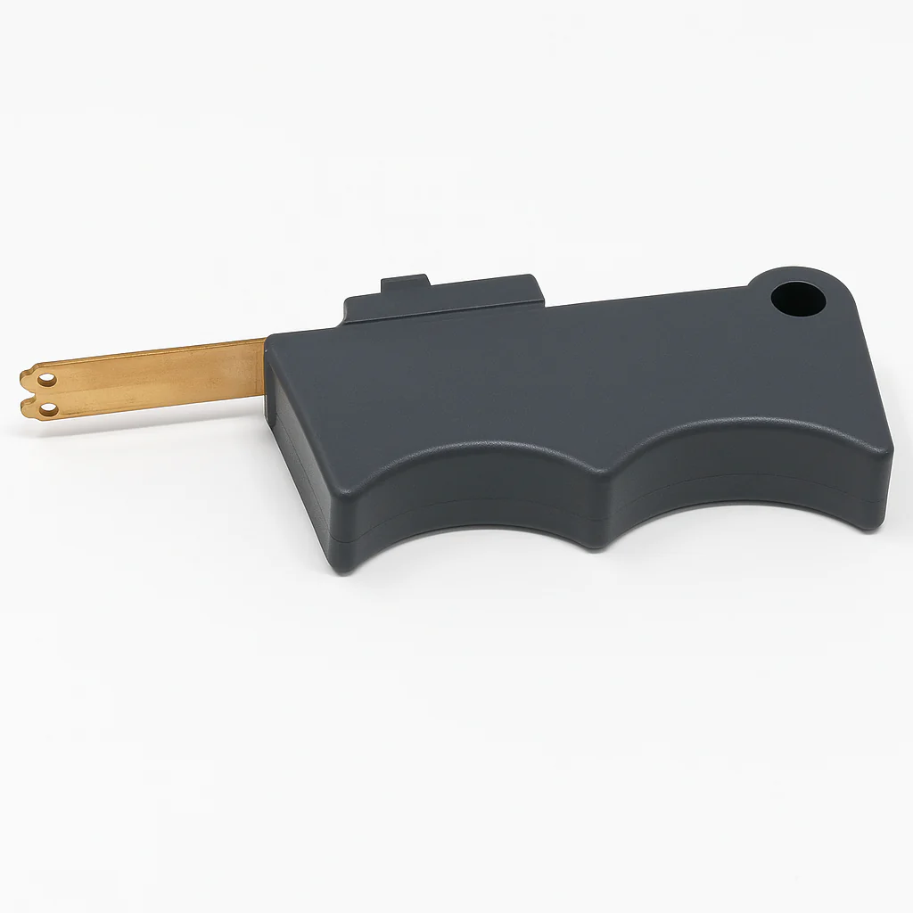
The Millermatic 252 and Millermatic 255 are both high-capacity Miller MIG welders designed for fabrication and production work, but they use very different platforms. The 252 is a traditional transformer-based machine focused on conventional MIG welding performance, while the 255 is a newer inverter platform with pulsed MIG capability, digital controls, and lower overall weight.
Quick Comparison
Feature
Millermatic 252
Millermatic 255
Platform
Transformer
Inverter
Processes
MIG / Flux Core
MIG / Pulsed MIG / Flux Core
Pulse MIG
No
Yes
Weight
~205 lb
~84 lb
Input Power
208/230V or multi-voltage versions
208–240V Auto-Line
Duty Cycle
250A @ 40%
230A @ 60%
Controls
Traditional knobs
Digital LCD + Auto-Set Elite
Best Use
Production steel fabrication
Mixed-material and aluminum fabrication
What Changes Most Between the 252 and 255
The biggest difference is pulsed MIG capability. The Millermatic 255 includes pulse settings that help reduce heat input, lower spatter, improve aluminum weld appearance, and make thin material easier to control.
The Millermatic 252 remains a very strong conventional MIG platform with excellent spray transfer performance on steel, especially in production environments.
Arc Characteristics
Millermatic 252
Smooth transformer arc
Excellent spray transfer performance
Strong performance on thicker steel
Very forgiving machine setup
Common in industrial fabrication shops
Millermatic 255
More responsive inverter arc
Pulse MIG reduces spatter
Better thin aluminum control
Digital tuning capability
Lower overall machine weight
Aluminum Welding Differences
The Millermatic 252 can weld aluminum effectively using a spool gun, especially on thicker material. However, the 255 performs better overall on thinner aluminum because pulse MIG reduces burn-through risk and lowers heat input.
For cosmetic aluminum fabrication, intermittent production, or mixed-material shops, the 255 is usually easier to dial in.
Weight and Portability
The 252 is significantly heavier because of its transformer design. It is commonly treated as a permanent shop machine.
The 255 is much lighter and easier to move between fabrication areas or job sites.
Common Consumable Verification Mistakes
Ordering M-Series consumables for MDX guns
Not verifying diffuser style
Wrong liner diameter for wire size
Incorrect drive rolls for aluminum wire
Assuming spool gun compatibility without checking connector configuration
What To Verify Before Ordering Parts
Gun model
Connector type
Wire diameter
Drive roll style
Diffuser type
Contact tip series
Spool gun compatibility
Which Machine Makes More Sense?
Choose the Millermatic 252 if:
You mainly weld steel
You want a proven transformer machine
You prioritize production welding
You prefer simpler controls
You commonly run spray transfer
Choose the Millermatic 255 if:
You weld aluminum regularly
You want pulse MIG capability
You move machines frequently
You want digital setup controls
You want lower spatter and cleaner starts
Bottom Line
The Millermatic 252 remains one of the most respected transformer MIG welders for steel fabrication and production environments. The Millermatic 255 adds modern inverter technology, pulse MIG capability, and improved aluminum performance while dramatically reducing machine weight.
For heavy steel production, many shops still prefer the 252. For mixed-material fabrication and modern welding flexibility, the 255 is usually the more capable overall platform.
Choosing between E70S-6 solid MIG wire and E71T-1 gas-shielded flux core wire affects weld appearance, penetration, deposition rate, cleanup time, outdoor usability, and productivity. While both are commonly used for carbon steel fabrication, they behave very differently in real shop conditions.
This guide compares ER70S-6 solid wire to E71T-1 flux-cored wire from a practical welding support perspective, including arc behavior, position capability, contamination tolerance, gas requirements, common failure paths, and what to verify before switching wire types.
Key Takeaways
ER70S-6 produces cleaner welds with lower slag and less post-weld cleanup.
E71T-1 typically provides higher deposition rates and deeper penetration.
E71T-1 handles thicker steel and out-of-position welding better in structural applications.
ER70S-6 is often preferred for automotive, fabrication, and cleaner shop environments.
E71T-1 generally tolerates mill scale and less-than-perfect surface conditions better.
Both wires require shielding gas, but gas type and polarity differ by application.
Incorrect polarity is a common cause of poor arc stability and excessive spatter.
What These Wires Actually Are
ER70S-6 is a solid mild steel MIG wire used with external shielding gas. The wire contains higher levels of manganese and silicon deoxidizers, helping it tolerate light mill scale and minor contamination better than some other solid wires.
E71T-1 is a tubular flux-cored wire that also uses external shielding gas. Unlike self-shielded flux core wires, E71T-1 relies on both internal flux ingredients and shielding gas for arc protection and slag formation.
Main Process Differences
Feature
ER70S-6 Solid MIG
E71T-1 Flux Core
Wire Type
Solid wire
Tubular flux-cored wire
Shielding Gas
Required
Required
Common Gas
75/25 Ar/CO2
75/25 or 100% CO2 (verify manufacturer data)
Polarity
DCEP
DCEP
Slag Production
Minimal
Moderate to heavy
Spatter
Lower
Moderate
Penetration
Moderate
Higher
Deposition Rate
Lower
Higher
Thin Material Control
Better
Harder to control
Outdoor Wind Resistance
Poor
Better but still gas-dependent
Cleanup Time
Lower
Higher due to slag
What This Means in Real Welding Conditions
ER70S-6 Solid Wire
ER70S-6 is commonly used where weld appearance matters and cleanup time needs to stay low. Automotive fabrication, light manufacturing, maintenance work, and thinner mild steel projects are common applications.
The arc is generally smoother and easier to control. This makes it easier for many welders to manage short-circuit transfer on thinner material without excessive burn-through.
However, ER70S-6 is more sensitive to wind and gas coverage issues. Porosity becomes common quickly when shielding gas flow is disrupted.
E71T-1 Flux Core
E71T-1 is widely used in structural steel, heavier fabrication, field repair, and production welding where deposition rate and penetration are priorities.
The flux system helps support the puddle during vertical and overhead welding. Many welders find E71T-1 easier for all-position work on thicker steel than solid wire.
The tradeoff is increased slag generation, more smoke, additional cleanup, and greater risk of slag inclusions if travel angle or interpass cleaning is poor.
Common Symptoms and Process Problems
Symptom
Likely With
Common Cause
Quick Check
Fix
Porosity
ER70S-6
Gas coverage loss
Check flowmeter and drafts
Increase shielding consistency
Slag inclusions
E71T-1
Poor slag removal
Inspect between passes
Clean thoroughly before reweld
Cold lap
Both
Low heat input
Inspect toe fusion
Adjust voltage/WFS
Excess spatter
Both
Incorrect settings or polarity
Verify polarity
Correct DCEP setup
Undercut
E71T-1
Excess travel speed
Inspect weld toes
Reduce travel speed
Burn-through
ER70S-6
Thin material overheating
Inspect backside
Lower voltage or increase travel speed
What Usually Wears Out First
Contact tips from wire abrasion and heat cycling
MIG nozzles from spatter accumulation
Drive rolls from flux dust contamination
Liners from flux residue buildup
Diffusers exposed to overheating and spatter blockage
Compatibility Notes
Before switching between ER70S-6 and E71T-1, verify:
Drive roll style and wire diameter compatibility
Correct polarity setup
Shielding gas type
Machine output capacity
Gun amperage rating
Liner condition
Duty cycle requirements
Wire feed system compatibility
Some smaller hobby MIG welders may struggle with larger diameter E71T-1 wires during extended duty cycles.
Verify machine manufacturer recommendations before running .045″ flux core wire or heavy structural applications.
What To Verify Before Ordering
Verify Item
Why It Matters
Wire Diameter
Affects feedability and amperage range
Spool Size
Must fit feeder hub and spindle
Shielding Gas Compatibility
Incorrect gas affects arc stability
Polarity Requirements
Wrong polarity creates severe arc issues
Gun Rating
Flux core often runs hotter
Application Position
Vertical welding behavior differs
Base Metal Thickness
Thin material may favor solid wire
Common Wrong-Part and Setup Mistakes
Using knurled drive rolls on solid wire
Running E71T-1 with incorrect shielding gas
Forgetting to reverse polarity after switching wire types
Using contaminated liners after flux core runs
Trying to weld thin automotive sheet metal with oversized flux core wire
Using low gas flow rates in drafty environments
Field Fix vs Proper Fix
Problem
Temporary Field Fix
Proper Fix
Birdnesting
Trim wire and rethread
Replace worn liner and inspect drive rolls
Poor gas coverage
Increase CFH temporarily
Repair leaks and block drafts
Slag inclusions
Grind and reweld area
Correct angle and clean between passes
Excessive spatter
Adjust settings slightly
Verify polarity, gas, and wire condition
Related Failure Paths
Porosity from poor gas coverage
Wire feeding instability from worn liners
Slag inclusions from improper cleaning
Lack of fusion from incorrect voltage settings
Contact tip overheating from excessive duty cycle
Excess smoke exposure from poor ventilation
Inspection Steps
Inspect wire for rust or contamination before loading.
Verify polarity directly at machine terminals.
Confirm gas flow with an actual flowmeter reading.
Check liner resistance while feeding wire.
Inspect nozzle and diffuser for blockage.
Examine weld toes for undercut or lack of fusion.
Remove all slag before additional E71T-1 passes.
Safety Notes
E71T-1 typically generates more fumes and smoke than ER70S-6.
Always maintain proper ventilation and respiratory protection when required.
Flux core slag can eject during chipping and grinding operations.
Verify correct PPE for grinding and weld cleanup.
Follow ANSI Z49.1 and OSHA welding safety guidance.
Both are commonly rated at 70 ksi tensile strength classifications, but E71T-1 often provides better penetration and higher deposition rates in structural applications.
Can E71T-1 be used outdoors?
Yes, but it still requires shielding gas. It handles mild wind better than solid wire, though excessive drafts still cause porosity.
Which wire is better for thin steel?
ER70S-6 is generally easier to control on thinner materials due to lower slag production and smoother short-circuit transfer characteristics.
Does E71T-1 require slag removal?
Yes. Slag should be fully removed between passes to avoid inclusions and weld defects.
Next Step
If your welds suffer from porosity, excessive spatter, feeding problems, or inconsistent penetration, inspect the full wire feed system before changing machines. Consumables, liners, drive rolls, polarity, and gas setup usually create more welding problems than the power source itself.
Sources Checked
AWS filler metal classification references
Lincoln Electric flux-cored wire documentation
Miller Electric MIG and flux core setup references
Soft aluminum MIG wire is hard to push through a standard MIG gun. It birdnests, shaves, slips at the drive rolls, and burns back into the tip right when the bead should be starting clean. The Lincoln Electric Magnum PRO 100SG spool gun, ASIN B00CP96KJO, is a replacement and upgrade path for welders who already own a compatible Lincoln machine and want more reliable aluminum wire feeding without fighting a long liner path.
This post focuses on troubleshooting aluminum MIG feed problems, when a spool gun makes sense, what wears first, what to verify before buying, and what spare consumables to keep with the gun.
Key Takeaways
The Lincoln Magnum PRO 100SG is a 4-pin spool gun, product number K3269-1, sold on Amazon under ASIN B00CP96KJO.
It is intended to improve feeding of soft aluminum wire by keeping the small wire spool at the gun instead of pushing aluminum through a long MIG gun liner.
Verify welder compatibility before buying; 4-pin does not mean universal.
The verified kit contents include a 10 ft cable, 0.035 in 4043 aluminum wire, 0.030–0.035 in drive roll, KP2744-035T contact tips, and an electrical harness with toggle switch.
Stock extra 0.035 contact tips and aluminum wire because tip wear, wire shaving, and burnback can still happen if setup is wrong.
The Problem: Aluminum Wire Keeps Birdnesting or Stuttering
If your aluminum MIG setup keeps birdnesting, the machine may not be the real problem. Aluminum wire is softer than steel wire, so it is easier to deform at the drive rolls and harder to push through a long cable. Once the wire gets scraped, flattened, or restricted, the feed becomes inconsistent and the arc starts popping, surging, or burning back.
Before replacing a welder, check the wire path. If the problem gets worse when the gun lead is looped, bent, or moved, you are probably dealing with friction, not a voltage setting. For more feed-path diagnosis, see best contact tips for MIG burnback and the MIG porosity fix guide.
Why a Spool Gun Fixes Many Aluminum Feed Problems
A spool gun moves the aluminum wire spool to the gun handle. Instead of pushing soft wire from the feeder, through a long liner, and out the contact tip, the gun feeds from a short path near the arc. That shorter path reduces the chance of wire shaving, liner drag, birdnesting, and feed hesitation.
The Lincoln Magnum PRO 100SG is best viewed as an aluminum MIG feed upgrade for compatible Lincoln compact wire feeder/welders, not as a universal fix for every MIG machine. If your welder is not listed for K3269-1 compatibility, treat fitment as Unknown (Verify).
Root Causes This Upgrade Helps Address
Soft aluminum wire shaving in the feeder.
Birdnesting caused by pushing aluminum through a long standard liner.
Feed stutter that changes when the gun lead bends.
Burnback caused by inconsistent wire delivery at the contact tip.
Arc starts that feel erratic even after cleaning the base metal and checking gas flow.
Root Causes It Will Not Fix
Wrong shielding gas for aluminum.
Dirty aluminum, oxide contamination, oil, or moisture.
Wrong contact tip size.
Incorrect spool gun tension or wire brake setup.
Unsupported welder compatibility.
Poor work clamp connection.
Operator technique problems, including excessive stickout or wrong gun angle.
Product Recommendation
Best overall upgrade for compatible Lincoln compact MIG machines: Lincoln Electric Magnum PRO 100SG Spool Gun, 4-pin, K3269-1.
No products found.
This is the main buy when your goal is to add aluminum MIG capability to a compatible Lincoln setup and reduce the feed problems that happen when soft wire is pushed through a standard MIG gun. It is not the budget choice compared with replacing a contact tip or liner, but it is the more serious upgrade path when aluminum work is recurring.
What to Verify Before Buying
Machine compatibility: Confirm your Lincoln welder supports K3269-1 / 4-pin Magnum PRO 100SG. Do not rely on connector shape alone.
Wire diameter: Verified setup information references 0.030–0.035 in aluminum wire capability. Your exact wire choice should match the gun setup and machine chart.
Wire alloy: Verified included wire is 0.035 in 4043 aluminum alloy. Other alloys require setup confirmation.
Duty cycle: Published seller/spec references list 130 amps at 30% duty cycle. Verify against Lincoln documentation for your exact package and application.
Consumables: The verified included contact tip part is KP2744-035T. Keep spares available before starting a project.
Comparison Table
Option
Best For
What It Solves
Limitations
Replace contact tip only
Cheap first troubleshooting step
Burnback, spatter-packed tip, poor current transfer
Will not fix long-path aluminum wire drag
Replace standard MIG liner
Steel MIG feed issues or contaminated liner
Stutter, drag, wire debris, rough feed
Still not ideal for soft aluminum wire on long leads
Lincoln Magnum PRO 100SG
Recurring aluminum MIG work on compatible Lincoln machines
Trigger/cable strain points: Inspect if feed cuts in and out when the cable moves.
Visual Wear Indicators
Wire burns back into the contact tip after short starts.
Aluminum shavings collect inside the gun or near the wire path.
The contact tip opening looks enlarged, oval, dark, or spatter-packed.
The wire exits with a scratchy or pulsing feel instead of a steady feed.
The bead has inconsistent width because wire speed is not staying stable.
Common Misdiagnosis
Many welders chase voltage and wire feed speed first. That can waste time. If the aluminum wire is not feeding smoothly, settings changes only hide the root cause. Confirm wire payoff, tip size, drive roll tension, gas coverage, and base-metal cleanliness before assuming the machine is defective.
If the weld has holes or black soot, do not blame the spool gun first. Aluminum porosity can come from poor cleaning, wrong gas, leaks, excess stickout, or contaminated filler. See the MIG porosity troubleshooting guide for gas and contamination checks.
If Ignored
Repeated birdnesting wastes aluminum wire and shop time.
Burnback can destroy contact tips and stop the weld mid-joint.
Wire shaving can contaminate the feed path and create more drag.
Inconsistent feed can cause poor fusion, ugly starts, and failed practice coupons or repairs.
Operators may over-tighten drive rolls, making soft-wire deformation worse.
Recommended Shop Setup
Lincoln Magnum PRO 100SG spool gun for compatible Lincoln machines.
Extra KP2744-035T 0.035 contact tips or verified equivalent.
Clean 0.035 in 4043 aluminum wire for general aluminum repair work where appropriate.
Dedicated stainless brush for aluminum cleaning.
Clean nozzle tools and anti-spatter workflow appropriate for your process.
Contact tips: Keep at least 5–10 verified 0.035 tips with the spool gun.
Aluminum wire: Keep one sealed spare 1 lb spool if aluminum repair work is recurring.
Nozzle: Keep one spare if your work creates heavy spatter or the gun travels to jobsites.
Cover lenses: Keep a multi-pack near the welder so visibility problems do not get mistaken for technique problems.
Related Failures
Birdnesting at the feeder after switching to aluminum wire.
Burnback into the contact tip during starts and stops.
Porosity after wire feed becomes inconsistent.
Spatter buildup around the nozzle and contact tip.
Poor weld pool visibility from scratched helmet lenses.
FAQ
Is B00CP96KJO the Lincoln Magnum PRO 100SG spool gun?
Yes. ASIN B00CP96KJO was verified as the Lincoln Electric Magnum PRO 100SG spool gun, commonly associated with Lincoln product number K3269-1.
Does the Magnum PRO 100SG fit every Lincoln welder?
No. It is a 4-pin spool gun for compatible Lincoln machines, but compatibility is not universal. Check your welder manual or Lincoln compatibility table before buying.
Will a spool gun stop all aluminum porosity?
No. A spool gun improves wire feeding, but porosity can still come from poor cleaning, oxide, moisture, wrong gas, leaks, drafts, or technique.
What wire size is the 100SG commonly set up for?
Verified product information references 0.030–0.035 in wire setup, with included 0.035 in 4043 aluminum wire. Verify your exact wire alloy and diameter against your welder setup chart.
What consumable should I buy with the spool gun?
Start with spare 0.035 contact tips that match the Magnum PRO 100SG setup. The verified included tip part is KP2744-035T. Also keep clean aluminum wire and replacement helmet cover lenses on hand.
Safety Notes
Disconnect input power before installing adapters, harnesses, or servicing the gun.
Follow the Lincoln manual for installation, setup, and machine compatibility.
Wear welding gloves, flame-resistant clothing, and eye/face protection rated for welding.
Use proper ventilation when welding aluminum and when running repeated test beads.
Do not troubleshoot live electrical connections unless qualified to do so.
Sources Checked
Lincoln Electric Magnum PRO 100SG K3269-1 product page.
Lincoln Electric Magnum PRO 100SG product literature PDF.
Lincoln Electric POWER MIG 215 MPi literature referencing K3269-1 package inclusion.
Lincoln Electric SP-140T literature referencing Magnum PRO 100SG 4-pin accessory details.
Amazon product identity check for ASIN B00CP96KJO.
Weld Support Parts internal posts on MIG burnback, porosity, wire feed issues, and helmet lens visibility.
MIG weld porosity is often blamed on shielding gas settings, but a blocked nozzle can cause the same problem. When spatter builds up inside the MIG gun nozzle, shielding gas flow can become restricted, uneven, or turbulent. The result may be pinholes, black soot, erratic arc behavior, and poor bead appearance.
This guide explains how nozzle spatter buildup causes gas coverage problems, what to check first, and how to clean and prevent buildup without damaging the gun consumables.
Key Takeaways
Spatter inside the MIG nozzle can restrict shielding gas and cause porosity.
A nozzle that looks acceptable from the outside may be blocked internally.
Nozzle gel can reduce spatter adhesion, but it should not be over-applied.
Contact tip, diffuser, and nozzle condition should be checked together.
Porosity troubleshooting should include gas leaks, flow rate, wind, base metal cleanliness, and consumable buildup.
Problem / Context
A MIG nozzle collects spatter during normal welding. If the buildup is not removed, it can narrow the gas path around the contact tip and diffuser. Shielding gas may still be flowing at the regulator, but the gas envelope at the weld puddle may be weak or uneven.
This issue is common when welding with short-circuit transfer, welding in tight corners, using excessive wire stickout, welding on dirty material, or running settings that create heavy spatter. It can also happen when the nozzle is dipped too deeply into anti-spatter compound.
Root Causes
Internal nozzle buildup: Spatter collects inside the nozzle and blocks the gas path.
Dirty diffuser: Spatter or debris around diffuser holes disrupts gas flow.
Damaged contact tip: A worn or oversized tip can cause unstable wire feeding and more spatter.
Excessive nozzle gel: Too much compound can contaminate the nozzle, contact tip, or weld area.
Incorrect settings: Voltage, wire speed, stickout, and travel angle can all affect spatter level.
External gas problems: Wind, leaks, low cylinder pressure, incorrect gas mix, or poor flow rate can also cause porosity.
Solution
Remove the nozzle and inspect the inside, not just the outside edge. If spatter is narrowing the opening or covering diffuser holes, clean the nozzle before adjusting the machine. Use proper MIG pliers or a nozzle cleaning tool rather than striking the nozzle against the workbench.
Turn off the welder before removing or servicing gun consumables.
Remove the nozzle and clear spatter from the inside wall.
Inspect the contact tip for wear, burnback, keyholing, or blocked wire passage.
Check the diffuser or gas ports for spatter blockage.
Reinstall consumables securely without cross-threading.
Apply nozzle gel lightly if used, keeping it away from the contact tip bore and weld joint.
Run a short test weld and inspect for porosity before continuing production work.
Specs / Verification Notes
Item to Verify
What to Check
Notes
MIG gun model
Nozzle, tip, and diffuser compatibility
Unknown (Verify)
Wire size
Contact tip size matches wire diameter
Unknown (Verify)
Shielding gas
Correct gas or gas mix for process
Unknown (Verify)
Gas flow
Flow at the gun, not only at the regulator
Unknown (Verify)
Nozzle condition
Internal spatter, deformation, loose fit
Replace if damaged
Diffuser condition
Blocked gas holes or damaged threads
Replace if damaged
Product Section
Nozzle gel can help reduce weld spatter adhesion inside a MIG nozzle. It should be used as a support item, not as a substitute for correct settings, clean consumables, and proper shielding gas coverage. Verify current product size, seller, and safety information before purchase.
No products found.
Comparison Table
Approach
Best Use
Risk
Routine nozzle cleaning
Daily MIG gun maintenance
May be skipped when production is rushed
Nozzle gel
Reducing spatter adhesion
Over-application can create contamination risk
Replacing nozzle
Damaged, distorted, or heavily packed nozzle
Wrong nozzle can affect gas coverage
Changing weld settings
Reducing excessive spatter at the source
Incorrect changes can create new weld defects
Safety Notes
Allow the nozzle and contact tip to cool before handling. MIG gun front-end parts can remain hot after welding.
Use safety glasses when removing spatter because fragments can break loose during cleaning.
Follow the product SDS for nozzle gel or anti-spatter compound handling and storage.
Keep anti-spatter compounds away from open flames unless the product documentation confirms safe use conditions.
Follow OSHA welding, cutting, and brazing requirements and ANSI Z49.1 safety guidance for welding, cutting, and allied processes.
FAQ
Can nozzle spatter cause MIG porosity?
Yes. Heavy spatter buildup inside the nozzle can interfere with shielding gas coverage and contribute to porosity.
How often should a MIG nozzle be cleaned?
Clean it whenever spatter buildup is visible inside the nozzle or when weld quality changes. High-spatter applications may require frequent cleaning during the job.
Can too much nozzle gel cause problems?
Yes. Excessive gel can collect debris or contaminate the contact tip and work area. Use a light amount and keep it out of the wire path.
Should the contact tip be replaced when cleaning the nozzle?
Inspect it at the same time. Replace the contact tip if it is worn, blocked, burned back, loose, or no longer feeding wire consistently.
What should be checked if the nozzle is clean but porosity remains?
Check gas flow at the gun, gas leaks, wind, base metal contamination, wire condition, polarity, and the correct gas type for the wire and process.
Next Step
If MIG porosity appears suddenly, remove the nozzle and inspect the gas path before changing the welder settings. Clean the nozzle, check the diffuser and contact tip, verify gas flow, then make a short test weld on clean material.
Sources Checked
Amazon product page for Forney Nozzle Gel 16 Oz, ASIN B00IOX4GBE
OSHA 1910.252 welding, cutting, and brazing general requirements
OSHA Eye Protection against Radiant Energy during Welding and Cutting fact sheet
AWS Eye and Face Protection for Welding and Cutting Operations fact sheet
ANSI Z49.1 safety guidance for welding, cutting, and allied processes
MIG burnback happens when the welding wire melts into the contact tip instead of feeding cleanly into the weld puddle. It is a common shop problem because the symptom looks simple, but the cause can come from wire speed, stickout, liner drag, contact tip wear, drive roll setup, or grounding.
This guide focuses on practical troubleshooting for short-circuit MIG welding where the wire repeatedly fuses to the contact tip, stalls at the gun, or creates inconsistent starts.
Key Takeaways
Burnback usually points to the wire melting faster than it is being delivered.
Low wire-feed speed, excessive liner drag, worn contact tips, or poor cable setup can all create the same symptom.
Do not solve repeated burnback by only increasing drive roll tension. That can deform the wire and create more feeding problems.
Contact tips should match the wire diameter and gun system. Unknown compatibility should be verified before ordering.
Any troubleshooting should include ventilation, eye protection, gloves, and control of hot work hazards.
Problem / Context
The typical sign is a wire end fused inside or at the face of the contact tip. The operator may hear the arc start, snap, and stop. In some cases, the wire birds-nests at the feeder after the wire path blocks at the tip.
Burnback is not always caused by a bad contact tip. The contact tip is often where the problem becomes visible, but the restriction may be farther back in the gun liner, drive rolls, spool brake, cable bend, or work lead connection.
Root Causes
Wire-feed speed too low: If the arc consumes wire faster than the feeder supplies it, the arc can climb back to the contact tip.
Stickout too short: Holding the gun too close reduces the distance between the contact tip and the weld puddle, increasing the chance of burnback.
Worn or dirty contact tip: An enlarged, oval, spatter-filled, or wrong-size tip can interrupt smooth wire delivery.
Dirty or kinked liner: Debris, metal shavings, or tight bends in the liner increase drag and cause inconsistent feeding.
Incorrect drive roll setup: Wrong groove type, wrong groove size, or excessive tension can slip, shave, or deform wire.
Gun cable bends: Tight loops or sharp bends make the feeder work harder and can cause wire speed variation at the arc.
Poor work connection: A loose or dirty work clamp can destabilize the arc and make starts less predictable.
Burnback control setting: Some machines have adjustable burnback timing. Incorrect adjustment can leave the wire too short after trigger release.
Solution
Start with the simplest checks before replacing multiple parts. Clip the wire clean, install a known-good contact tip that matches the wire diameter, and confirm the wire feeds through the gun without unusual resistance.
Confirm the contact tip size matches the wire being used.
Check the machine settings against the wire size, material thickness, shielding gas, and transfer mode.
Increase wire-feed speed slightly if the wire is burning back immediately at arc start.
Hold a consistent contact-tip-to-work distance instead of pushing the nozzle too close to the puddle.
Remove the contact tip and feed wire through the gun. If feeding improves, replace the tip.
If resistance remains with the tip removed, inspect the liner, gun cable bends, and feeder path.
Check drive roll size, groove type, pressure, and wire spool brake tension.
Clean the work clamp area and confirm the work lead connection is tight.
Review burnback timer settings only after the mechanical feeding path is confirmed.
Specs / Verification Notes
Item to Verify
Why It Matters
Status
Wire diameter
Contact tip and drive roll groove must match the wire size.
Unknown (Verify)
Contact tip thread/system
Tips are not universal across all MIG guns.
Unknown (Verify)
Liner size
A liner that is too small, worn, kinked, or contaminated can create drag.
Some MIG machines include adjustable burnback timing.
Unknown (Verify)
Product Section
The product below was checked as an Amazon listing with a visible ASIN. Confirm wire diameter, thread style, gun compatibility, and seller details before purchase.
Comparison Table
Symptom
Likely Area
Check First
Wire fuses to tip immediately
Wire-feed speed or stickout
Increase wire feed slightly and maintain proper gun distance.
Wire feeds unevenly before burnback
Liner, drive rolls, spool brake
Inspect the full wire path for drag or slipping.
Tip hole looks oval or spattered
Contact tip wear
Replace with the correct size tip.
Bird-nesting at feeder
Blocked path near gun or tip
Remove the tip and test wire feed through the gun.
Arc starts harsh or unstable
Work connection or settings
Clean the work clamp area and verify voltage and wire-feed settings.
Safety Notes
Follow ANSI Z49.1 guidance for welding, cutting, and allied processes. Use appropriate eye, face, hand, and body protection, and keep the work area controlled for sparks, heat, and fire hazards.
AWS safety guidance also emphasizes adequate ventilation for welding and cutting. Keep the breathing zone out of the fume plume and use local exhaust or other controls where required.
Disconnect power according to the equipment manual before servicing feeder components, gun liners, or internal machine parts. Hot contact tips and nozzles can cause burns even after welding stops.
FAQ
Does burnback always mean the contact tip is bad?
No. A worn or dirty contact tip can cause burnback, but liner drag, low wire-feed speed, tight cable bends, incorrect drive rolls, or a poor work connection can also cause the same symptom.
Should drive roll tension be increased when burnback happens?
Only after checking the rest of the wire path. Too much drive roll tension can deform the wire, create metal shavings, and make liner contamination worse.
Can stickout cause burnback?
Yes. If the contact tip is held too close to the weld puddle, the arc has less wire length between the tip and the work. That can increase burnback risk, especially during starts and stops.
How often should MIG contact tips be replaced?
There is no single replacement interval for every shop. Replace the tip when the bore is worn, oval, spatter-blocked, feeding becomes inconsistent, or arc starts become unreliable.
Can burnback timing fix the problem?
Sometimes, but only after confirming the mechanical feed path is correct. Burnback timing should not be used to hide a worn tip, dirty liner, or incorrect drive roll setup.
Next Step
For repeated MIG burnback, replace the contact tip with the correct size, straighten the gun cable, test wire feed with the tip removed, and inspect the liner if resistance remains. Verify consumable compatibility before ordering replacement tips.
Sources Checked
Amazon product listing checked for ASIN B0GG66ZVBD.
American Torch Tip: causes of contact tip burnback.
Hobart Brothers: common wire feeding issues and contact tip wear.
General Air: wire feeding problems, liners, contact tips, drive rolls, and welding circuit checks.
AWS ANSI Z49.1 safety guidance for welding, cutting, and allied processes.
AWS Safety and Health Fact Sheet: ventilation for welding and cutting.
MIG nozzle gel is used to reduce weld spatter buildup on MIG gun nozzles and contact tips. It is not a fix for poor settings, contaminated wire, bad gas coverage, or worn consumables. Used correctly, it can help keep the front end of a MIG gun cleaner during short-arc and general shop welding work.
Key Takeaways
Nozzle gel helps limit spatter sticking to MIG nozzles and contact tips.
It should be applied lightly. Excess gel can create contamination concerns.
It does not correct voltage, wire feed, shielding gas, or stickout problems.
Always verify the product label and safety data before use.
Keep gel containers away from arc heat, sparks, grinding dust, and open flame unless the label specifically allows the exposure.
Problem / Context
MIG spatter often collects inside the nozzle and around the contact tip. As buildup increases, shielding gas flow can become restricted, the arc may become less stable, and the operator may need to stop more often to clean the gun.
Nozzle gel is a maintenance aid for the MIG gun front end. It creates a temporary barrier that helps reduce spatter adhesion. It should be treated as support equipment, not as a substitute for proper setup.
Root Causes
Incorrect voltage or wire-feed speed for the wire size and material thickness.
Excessive stickout.
Poor work clamp connection.
Dirty base metal, mill scale, oil, paint, or rust.
Wrong shielding gas mix or incorrect gas flow.
Drafts disturbing shielding gas coverage.
Worn contact tip, damaged nozzle, or loose front-end parts.
Poor travel angle or inconsistent gun distance.
Solution
Clean the nozzle before applying gel.
Dip only the hot front end of the nozzle lightly, unless the manufacturer gives different instructions.
Do not pack gel into the nozzle bore.
Keep gel away from the weld joint, especially on code work or critical welds.
Reapply only as needed after cleaning spatter.
Replace damaged nozzles and contact tips instead of trying to compensate with more gel.
Specs / Notes
Item
Notes
Process
MIG / GMAW support
Primary use
Reducing spatter adhesion on nozzle and contact tip area
Compatible metals
Unknown (Verify)
Temperature rating
Unknown (Verify)
Silicone-free status
Unknown (Verify)
Paintable surface suitability
Unknown (Verify)
Code welding suitability
Unknown (Verify with procedure, inspector, and product SDS)
Storage
Verify label and SDS before shop use
Product Section
Verified Amazon ASIN found for a MIG nozzle gel product:
No products found.
Product note: The Amazon listing identifies this item as Forney 37031 Nozzle Gel For Mig Welding, 16-Ounce, White, with ASIN B00IOX4GBE. Verify current availability, label details, SDS, and shop suitability before use.
Shop Reference Table
Condition
Likely Check
Nozzle Gel Role
Light spatter on nozzle
Confirm settings and clean nozzle
Helpful as a light barrier
Heavy spatter after every weld
Check voltage, wire speed, gas, stickout, and base metal cleanliness
May help cleanup but will not solve root cause
Porosity appears
Check gas coverage, drafts, contamination, and consumables
Stop and inspect; do not add more gel near weld area
Nozzle bore restricted
Remove spatter and inspect nozzle
Clean first, then apply lightly
Critical weld procedure
Confirm approved consumables and procedure limits
Use only if allowed by procedure and inspector
Safety: ANSI / AWS / OSHA Notes
AWS/ANSI Z49.1:2021 covers safety and health in welding, cutting, and allied processes, including protection of personnel, ventilation, fire prevention, confined spaces, and general-area protection. OSHA identifies welding, cutting, and brazing hazards that include metal fumes, ultraviolet radiation, burns, eye damage, electrical shock, cuts, and crush injuries.
Maintain ventilation suitable for the welding process and material.
Keep the gel container closed when not in use.
Do not place containers where sparks, hot slag, or grinding debris can enter.
Review the product SDS before use, especially in enclosed areas or production work.
Follow local hot-work, fire-watch, and shop safety requirements.
FAQ
Does nozzle gel stop all MIG spatter?
No. It helps reduce spatter sticking to the nozzle and contact tip area. It does not eliminate spatter caused by poor setup, contamination, or worn parts.
Can nozzle gel cause weld contamination?
It can if overused or transferred into the weld area. Apply lightly and keep it away from the joint. For critical welding, verify acceptability with the welding procedure, inspector, and SDS.
Should the contact tip be dipped into gel?
Follow the product label. In general shop practice, the front end is treated lightly to reduce spatter adhesion. Avoid packing gel into the nozzle or creating buildup around the wire path.
Is nozzle gel the same as anti-spatter spray?
No. Nozzle gel is typically used at the MIG gun front end. Anti-spatter spray is commonly applied to work surfaces, fixtures, or surrounding areas when allowed by the application. Always verify the product label.
Can nozzle gel be used for TIG or stick welding?
This post is focused on MIG / GMAW front-end support. Use for other processes is Unknown (Verify) unless the specific product label states otherwise.
Next Step
Before adding more nozzle gel, clean the MIG gun front end and check voltage, wire feed, stickout, shielding gas flow, work clamp contact, and base metal cleanliness. Use gel lightly after the root causes of excessive spatter have been reviewed.
Sources
Amazon product listing: Forney 37031 Nozzle Gel For Mig Welding, 16-Ounce, White. ASIN: B00IOX4GBE.
American Welding Society: AWS/ANSI Z49.1:2021 Safety in Welding, Cutting, and Allied Processes.
OSHA: Welding, Cutting, and Brazing hazards and solutions.
OSHA: 29 CFR 1910.252 General Requirements for Welding, Cutting, and Brazing.
Porosity in MIG welds shows up as pinholes, surface bubbles, or internal voids that weaken the joint. It’s one of the most common—and preventable—issues in shop welding. The root cause is always the same: contamination or inadequate shielding gas coverage.
Key Takeaways
Porosity is caused by gas coverage failure or contamination
The most common issues are gas flow, leaks, and dirty material
Wind, improper nozzle distance, and bad technique can all introduce air
Fixes are usually simple: clean, adjust flow, check equipment
What’s Causing the Problem
1) Poor Shielding Gas Coverage
Flow rate too low or too high (turbulence)
Leaks in hoses or fittings
Blocked or dirty nozzle/diffuser
2) Contaminated Base Metal
Oil, rust, mill scale, paint, or moisture
Galvanized coatings releasing gas during welding
3) Environmental Factors
Wind or drafts blowing shielding gas away
Outdoor welding without protection
4) Incorrect Technique
Stickout too long (reduces gas effectiveness)
Travel angle pushing gas away from puddle
Moving too fast for proper shielding
How to Fix It
Step 1: Set Proper Gas Flow
Typical MIG range: 20–30 CFH (9–14 L/min)
Indoors: stay near 20–25 CFH
Outdoors: increase slightly or use wind blocks
Step 2: Check for Leaks
Inspect all connections from tank to gun
Listen for hissing or use leak detection fluid
Replace cracked hoses or worn O-rings
Step 3: Clean the Material
Grind to bright metal before welding
Remove coatings, oil, and moisture
Use acetone if needed (let fully evaporate)
Step 4: Inspect Gun Components
Clean or replace nozzle and diffuser
Ensure no spatter is blocking gas flow
Confirm proper contact tip size
Step 5: Adjust Technique
Keep stickout around 3/8″–1/2″ (10–12 mm)
Maintain steady travel speed
Use correct gun angle (10–15° push or drag)
Common Mistakes to Avoid
Running gas too high (creates turbulence)
Welding over dirty or painted surfaces
Ignoring small gas leaks
Letting spatter clog the nozzle
Welding in open air without shielding from wind
Best Settings / Guidelines
Parameter
Typical Range
Gas Flow
20–30 CFH (9–14 L/min)
Stickout
3/8″–1/2″ (10–12 mm)
Travel Angle
10–15°
Wire Speed
Varies by machine/material
Voltage
Varies by machine/material
Always confirm with your machine’s chart or manufacturer specs.
Safety Notes
Wear proper eye protection (ANSI Z87.1) and welding helmet
Avoid inhaling fumes—especially on coated or galvanized steel
Ensure adequate ventilation when cleaning with solvents
Keep gloves and sleeves dry to prevent contamination and burns
FAQ
What does porosity look like in a weld? Small holes, bubbles, or pits on the surface or inside the weld bead.
Can porosity be fixed after welding? Not reliably—grind out the affected area and reweld with proper prep.
Is too much gas flow bad? Yes—excessive flow can create turbulence and pull in air.
Does wire type affect porosity? Yes—low-quality or contaminated wire can introduce gas pockets.
Can humidity cause porosity? Yes—moisture on the material or in the air can contribute.
Sources Checked
American Welding Society (general guidance on shielding gas and weld quality)
Lincoln Electric application notes on MIG porosity causes
Miller Electric troubleshooting resources for shielding gas issues
Porosity in MIG welding shows up as pinholes or small voids in the weld bead. It weakens the weld and usually points to shielding gas failure or contamination. This guide breaks down the exact causes and the fastest way to fix it using proper setup and wire selection.
Key Takeaways
Porosity is caused by poor shielding gas coverage or contamination
Dirty metal and bad wire are the most common causes
Gas flow, nozzle condition, and wire choice fix most issues
ER70S-6 wire helps reduce porosity on less clean steel
What Causes MIG Weld Porosity
Porosity occurs when atmospheric gases get trapped in the weld pool as it solidifies. In MIG welding, shielding gas is supposed to prevent this. When coverage fails, defects form.
Low shielding gas flow
Wind or airflow disrupting gas
Dirty or oily metal
Rusty or contaminated wire
Improper stickout or angle
Clogged nozzle or diffuser
How to Fix MIG Porosity
Set gas flow to 20–30 CFH (verify for your setup)
Keep stickout around 3/8”–1/2”
Clean metal to bare steel
Check for gas leaks
Replace worn nozzle or diffuser
Switch to ER70S-6 wire if needed
Recommended Wire for Reducing Porosity
Hobart ER70S-6 MIG Welding Wire (.030”)
Type: Solid MIG wire
Diameter: .030”
Material: Mild steel
Deoxidizers: Higher than ER70S-3
Specs: Unknown (Verify)
No products found.
ER70S-6 wire is more forgiving on dirty steel and helps reduce porosity compared to ER70S-3.
Gas Flow Setup
Typical: 20–30 CFH (verify)
Too low = poor coverage
Too high = turbulence
Avoid drafts when welding
Wire Comparison
Wire
Key Difference
Best Use
ER70S-6
More deoxidizers
Dirty steel
ER70S-3
Cleaner arc
Clean material
Safety Notes
Use ANSI Z87.1 compliant eye protection and proper PPE. Ensure ventilation and follow AWS welding safety guidelines.
FAQ
Q: Can too much gas cause porosity? A: Yes. It can create turbulence and pull in air.
Q: Does wire matter? A: Yes. ER70S-6 is more forgiving on dirty steel.
Next Step
Check your gas flow and nozzle first. If needed, switch to ER70S-6 wire and clean your material before welding.
A weak ground clamp causes arc instability, poor starts, and wasted time. If the clamp is loose, corroded, or undersized for the job, the machine cannot deliver a consistent return path.
For a simple replacement path, the FGC200 Ground Clamp 200 Amp is a verified option to check first. The key is matching the clamp to the current load and the cable setup you already run.
When to replace the clamp
Arc starts are erratic
The clamp jaws are dirty or burnt
The spring tension is weak
The cable connection is damaged
You need a new clamp for a 200 amp class setup
Compatibility table
Part type
Part number
Compatible models
Notes
Use cases
Ground clamp
FGC200
Welding setups using a 200 amp clamp class
Confirm cable lug size and connection method before ordering
MIG, TIG, Stick return path
Work clamp
FGC200
General welding machine ground leads
Match amperage needs to the workpiece and cable size
Shop and field welding
Copy table
AAWP box:
No products found.
What to verify before you buy
Cable connection style
Lug or clamp attachment method
Current demand of the machine and workpiece
Clamp jaw condition and contact surface
Recommended use case
Choose this clamp if you need a straightforward replacement for a worn ground clamp in a 200 amp class setup and want a simple upgrade path without changing the rest of the lead assembly.
Safety note
Shut the machine off before replacing the clamp. Make sure the work lead is connected correctly and the contact surface is clean. For structural work, follow the applicable welding procedure and code requirements.
If your MIG gun trigger is intermittent, stuck, or dead, the fix is often the switch—not the entire gun. The 94R Tweco MIG Gun Trigger Switch Assembly is a replacement trigger switch intended for compatible Tweco-style MIG gun handles. It’s a small part, but it directly affects arc starts, wire feed consistency, and overall uptime. Fitment matters here—verify compatibility before ordering.
Key Specs
Spec
Value
Product
94R Tweco MIG Gun Trigger Switch Assembly
SKU
2040-2096
Welding process
MIG (GMAW/FCAW)
Part type
Trigger switch assembly
Compatible guns/handles
Unknown (Verify)
Electrical rating
Unknown (Verify)
Included hardware
Unknown (Verify)
Price (ArcWeld.store)
Unknown (Verify)
Best For
MIG guns where the trigger is cutting out, double-clicking, or not feeding wire consistently
Shops that want to repair the gun instead of replacing the whole assembly
Maintenance bins for common failure items (trigger switches are wear parts)
Troubleshooting scenarios where you’ve already ruled out:
Loose liner/lead connections
Broken trigger leads at the strain relief
Machine-side trigger circuit issues
Pros & Cons
Pros
Replaces a common failure point without buying a full MIG gun
Helps restore consistent starts and wire feed (when the trigger is the root cause)
Small, low-downtime repair if you already know the handle style
Good “keep one on the shelf” part for production environments
Cons
Fitment is not universal—must match your gun/handle style (Unknown (Verify))
Electrical rating and connector style not listed on the store page (Unknown (Verify))
Installation may require opening the handle and routing leads correctly
If the issue is in the lead/machine trigger circuit, a new switch won’t fix it
Current price: Unknown (Verify) CTA: Buy now at Arc Weld.store
Bottom Line
If your MIG gun is acting like it has a “bad trigger,” this is a practical repair part—but only after you confirm fitment for your exact gun/handle.
Manage Consent
To provide the best experiences, we use technologies like cookies to store and/or access device information. Consenting to these technologies will allow us to process data such as browsing behavior or unique IDs on this site. Not consenting or withdrawing consent, may adversely affect certain features and functions.
Functional
Always active
The technical storage or access is strictly necessary for the legitimate purpose of enabling the use of a specific service explicitly requested by the subscriber or user, or for the sole purpose of carrying out the transmission of a communication over an electronic communications network.
Preferences
The technical storage or access is necessary for the legitimate purpose of storing preferences that are not requested by the subscriber or user.
Statistics
The technical storage or access that is used exclusively for statistical purposes.The technical storage or access that is used exclusively for anonymous statistical purposes. Without a subpoena, voluntary compliance on the part of your Internet Service Provider, or additional records from a third party, information stored or retrieved for this purpose alone cannot usually be used to identify you.
Marketing
The technical storage or access is required to create user profiles to send advertising, or to track the user on a website or across several websites for similar marketing purposes.