Tag: wire feed

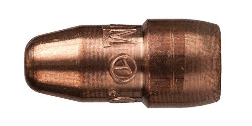
  • 000-068 Miller Style M-Series Contact Tip .035 – Arc Weld by Masterweld Pack of (25): Replacement Part Breakdown

    If you are maintaining a MIG gun, the contact tip is a wear item that directly affects arc stability and wire feed consistency. The product listed here is the 000-068 Miller Style M-Series Contact Tip .035 – Arc Weld by Masterweld Pack of (25) for ASIN B07Y3SCYB7. This draft is written as a replacement-part breakdown for buyers and support teams who need a practical way to evaluate a tip before installing it.

    Because tip compatibility can vary by gun, diffuser, neck style, and wire diameter, treat any fitment assumption as Unknown (Verify) unless your equipment manual or parts breakdown confirms it. Do not assume “Miller style” means universal compatibility across all Miller MIG guns.

    Key Takeaways

    • A contact tip is a consumable wear part, not a permanent component.
    • The stated wire size is .035; verify your wire diameter before installation.
    • Fitment depends on the gun model and front-end consumables. Verify against the machine manual or parts list.
    • Poor tip condition can cause inconsistent arc starts, feeding issues, and heat-related wear.
    • Pack quantity is listed as 25 in the product name, but do not assume packaging details beyond the listing title without checking the source page.

    What a Contact Tip Does

    The contact tip transfers welding current to the wire while guiding the wire through the gun’s front end. If the bore is worn, oversized, blocked, or contaminated, the wire can hesitate or arc quality can drop. In maintenance terms, the tip is a small part with a large effect on production consistency.

    How to Evaluate This Part Before Use

    Check: Confirm the wire diameter matches the tip size. For this item, that means .035 wire only unless your procedure and equipment documentation say otherwise.

    Inspect: Look at the tip threads, seating surfaces, bore, and visible finish before installing. Reject damaged, cross-threaded, or contaminated parts.

    Verify: Confirm the front-end components in your gun assembly. A Miller style M-Series label does not by itself confirm exact gun compatibility.

    Check: Compare the replacement tip to the removed tip. Length, shoulder profile, thread style, and seating geometry should match the original part.

    Inspect: After installation, test wire feed by jogging wire at low speed. The wire should pass smoothly without catching or stubbing at the tip.

    Verify: Run a short test weld and confirm arc starts, sound, and wire feeding are stable. If you see burnback, wandering arc, or erratic feed, stop and re-check the tip and liner system.

    Troubleshooting Support: When a Tip Creates Problems

    If a contact tip seems to fail too soon, do not assume the part is the only issue. Tip wear is often caused by system-level problems.

    Check: Wire diameter. A .030 wire in a .035 tip may increase electrical contact variability, while a wire that is too large can bind. Verify actual wire size first.

    Inspect: Liner condition. A dirty or worn liner can push wire inconsistently and accelerate tip wear.

    Check: Drive roll tension and drive roll type. Too much pressure can deform wire and create feed surges; too little can slip.

    Inspect: Gun neck, diffuser, and nozzle alignment. Misalignment can cause off-center wear on the tip.

    Verify: Contact-tip-to-work distance and welding parameters against the procedure. Excessive heat load can shorten consumable life.

    Check: For spatter buildup at the tip opening after each shift. Heavy spatter can block the bore and mimic wire-feed failure.

    Inspect: For burnback evidence. If the wire fuses to the tip, review feed speed, voltage, stickout, and shielding gas coverage.

    Product / Parts Notes

    This page covers the listed Amazon product only: 000-068 Miller Style M-Series Contact Tip .035 – Arc Weld by Masterweld Pack of (25), ASIN B07Y3SCYB7. No additional product specifications should be assumed beyond the provided listing name. Any exact dimensional, thread, material, or certification detail is Unknown (Verify) unless confirmed by the source listing or your internal parts documentation.

    For purchasing teams, the main check is whether your installation needs a Miller style M-Series .035 contact tip and whether the replacement part matches the original front-end setup. If the gun model is uncertain, use the machine’s parts breakdown or a qualified service record before ordering in volume.

    Related Support Reference

    If you need a broader material-selection example for MIG work, use the internal article below as a starting point for wire selection context. It is a support reference, not a procedure approval for this contact tip.

    Safety Notes

    • Lock out welding power when servicing front-end consumables where your site procedure requires it.
    • Allow hot parts to cool before handling.
    • Wear appropriate gloves and eye protection when changing tips or clearing spatter.
    • Do not force a tip into a mismatched diffuser or gun front end.
    • If a consumable repeatedly fails, stop and diagnose the gun assembly instead of cycling parts.

    FAQ

    Is this contact tip only for .035 wire?
    The product name states .035. Verify the wire diameter on your job before use. Do not guess.

    Will a Miller style M-Series tip fit every Miller MIG gun?
    No. That is not safe to assume. Gun model, front-end design, and diffuser style must be verified against the machine parts breakdown.

    What should I check if wire feeding becomes erratic after tip replacement?
    Check liner condition, drive roll setup, wire diameter, spatter buildup, and alignment at the gun front end. Then verify the tip is seated correctly.

    Can I use the same tip for every weld process?
    No. Contact tips are wire-size and gun-specific wear parts. Verify against the exact process and equipment setup.

    Sources Checked

    • Provided Amazon product identifier and listing name for ASIN B07Y3SCYB7
    • Allowed internal link: Weld Support Parts blog article on Aluminum ER 5554 MIG wire

    Note: No WSP lookup page or filler metal finder page was provided in the allowed inputs for this task, so none were included.

    Matched Replacement Option

    No products found.

    Disclosure: As an Amazon Associate, Weld Support Parts may earn from qualifying purchases.

    Related Weld Support Guides

  • Tweco 44-116-25, Replacement Liner/Conduit, Pack of (1): Product Breakdown

    Tweco 44-116-25, Replacement Liner/Conduit, Pack of (1): Product Breakdown

    Product not found.
    “>Tweco 44-116-25, Replacement Liner/Conduit, Pack of (1)

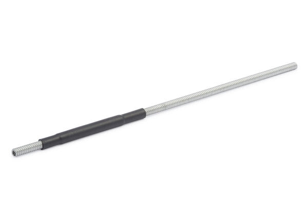
    If a MIG gun starts feeding erratically, the liner is one of the first wear parts to inspect. The Tweco 44-116-25, Replacement Liner/Conduit, Pack of (1) is listed as a 1/16″ x 25′ zinc plated MB spring wire liner intended for certain Tweco MIG gun families. For maintenance buyers and welding support teams, the key question is not just what the part is called, but whether it matches the gun, wire, and feed path you are servicing.

    This breakdown stays focused on practical use: what to verify before ordering, what to inspect during install, and how to troubleshoot feeding problems after replacement. Where technical details are not confirmed by the provided source, they are marked Unknown (Verify).

    Key Takeaways

    • The Tweco 44-116-25 is a replacement liner/conduit, not a complete gun assembly.
    • The supplied product description identifies it as a 1/16″ x 25′ zinc plated MB spring wire liner.
    • Listed gun families include 300 – 500 amp Tweco Eliminator, Tweco Spray Master, Tweco No. 3, Tweco No. 4, and Tweco No. 5 X-Gun MIG guns.
    • Final fit depends on gun model, cable length, wire diameter, and feed setup. Verify before purchase.
    • If the liner is the wrong type or length, feeding problems can persist even when the drive rolls are in good condition.

    What This Part Does

    A MIG gun liner guides wire from the feeder through the cable to the contact tip. In service, the liner must stay smooth internally and properly matched to the wire being run. A spring-style liner can support feeding in heavier-duty applications, but the correct selection still depends on the specific gun and application. The source listing identifies the liner as zinc plated MB spring wire liner, but any additional material details beyond that are Unknown (Verify).

    Check Before You Order

    Use these checks before replacing a liner:

    • Inspect the gun model. Confirm the MIG gun family on the handle, cable tag, or service record.
    • Verify cable length. The product is listed as 25′. Match this to the gun cable length in service.
    • Check wire diameter. The listing includes 1/16″ in the product description, but verify the actual wire size in your process.
    • Review the feed symptom. Birdnesting, inconsistent feed speed, and wire scrape marks can point to liner wear or mismatch.
    • Inspect the current liner. Look for scoring, rust, debris, kinks, or crushed sections.

    Verify: If the existing liner was changed to solve a problem once before, confirm whether the root cause was actually the liner or another part of the feed system. Drive rolls, inlet guides, gun neck angle, and cable routing can create similar symptoms.

    Troubleshooting Support

    When wire feed is unstable, go through the system in order.

    1) Feed from the feeder first

    • Inspect: Drive roll condition and tension.
    • Check: Inlet guide alignment into the gun connection.
    • Verify: The wire feeds smoothly before it enters the gun cable.

    2) Move to the cable

    • Inspect: Cable bends, crushed areas, and twist points.
    • Check: Whether the gun is being used in a tight routing position that increases drag.
    • Verify: The cable is not damaged externally before replacing the liner.

    3) Check the liner itself

    • Inspect: Liner ends for burrs or deformation.
    • Check: Internal wear by comparing feed feel before and after removal.
    • Verify: The liner path is clean and free of contamination from old wire dust or rust.

    4) Confirm the contact tip and neck components

    • Inspect: Tip wear and bore condition.
    • Check: Whether the tip matches the wire size in use.
    • Verify: Heat damage or spatter build-up is not causing the wire to bind.

    If feeding improves after the liner change but problems return quickly, do not assume the liner was the only issue. Verify wire quality, spool condition, and whether the process is pushing the gun beyond its normal duty conditions. Any exact compatibility outside the product listing remains Unknown (Verify).

    Installing a Replacement Liner: Practical Steps

    1. Power down the machine and isolate the welding circuit.
    2. Remove the consumables and release wire tension.
    3. Withdraw the old liner carefully to avoid leaving fragments in the cable.
    4. Inspect the cable path for debris, wear, or internal obstruction.
    5. Insert the new liner slowly and keep it from kinking.
    6. Trim only as required by the gun setup after confirming length and seating.
    7. Reassemble the gun and reinstall consumables.
    8. Test feed at low speed first, then verify under normal operating settings.

    Verify: The source listing does not provide installation tolerances, trim allowances, or torque values. Those details are Unknown (Verify) and should be taken from the gun manufacturer’s service documentation.

    When to Replace Instead of Clean

    Cleaning can help when the liner is only contaminated. Replacement is usually the better choice when the liner is scored, rusted, crushed, or repeatedly causing drag after the rest of the feed path has been checked. If a gun is used in a high-production environment, a liner may become a scheduled wear item rather than an emergency repair part.

    Product and Parts Notes

    The provided ArcWeld product listing identifies this item as the Tweco 44-116-25, Replacement Liner/Conduit, Pack of (1). The short description states it is a 1/16″ x 25′ zinc plated MB spring wire liner for use with 300 – 500 amp Tweco Eliminator, Tweco Spray Master, Tweco No. 3, Tweco No. 4, and Tweco No. 5 X-Gun MIG guns. No additional compatibility should be assumed beyond that listing. If your gun variant differs from the named families, verify before ordering.

    Product reference:

    Tweco 44-116-25, Replacement Liner/Conduit, Pack of (1)

    Tweco 44-116-25, Replacement Liner/Conduit, Pack of (1)

    Tweco Model 44-116-25 1/16" X 25' Zinc Plated MB Spring Wire Liner For Use With 300 – 500 Amp Tweco® Eliminator®, Tweco® Spray Master®, Tweco® No. 3, Tweco® No. 4, Tweco® No. 5 X-Gun MIG Guns

    View at Arc Weld Store

    For related feed-wire context, see this internal article: Aluminum ER 5554 3/64″ X 5lb. MIG Welding Wire Spool By Washington Alloy – Weld Support Parts Blog. That page is not a liner guide, but it can help support teams think through wire handling and feed consistency when reviewing the whole system.

    Safety Notes

    • De-energize equipment before service.
    • Keep hands clear of sharp wire ends during liner removal and trim.
    • Do not force a liner into a cable if it binds; inspect the cable and gun path first.
    • Use the correct personal protective equipment for shop service work.
    • Follow the gun and power source manufacturer’s service instructions where available.

    FAQ

    Is the Tweco 44-116-25 a complete gun?

    No. It is a replacement liner/conduit only, based on the provided product listing.

    Can I use this liner on any Tweco gun?

    No. The listing names specific Tweco gun families, but final fit still needs to be verified against your exact model and cable setup. Unknown (Verify) for any unlisted variants.

    What usually causes feeding issues if the liner is new?

    Drive roll tension, damaged cable routing, incorrect tip size, dirty wire, or a mismatched liner can still cause feed problems. Verify the full feed path, not just the liner.

    Should I clean the old liner or replace it?

    Clean only if contamination is the likely issue and the liner is still in serviceable condition. Replace it if there is scoring, rust, deformation, or recurring drag.

    Sources Checked

    • ArcWeld product listing: Tweco 44-116-25, Replacement Liner/Conduit, Pack of (1)
    • Provided internal product description and source URL for the same item
    • Allowed internal link: Weld Support Parts blog article on aluminum MIG wire handling

    Related Weld Support Guides

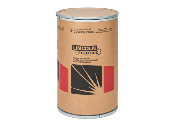
  • Lincoln Electric SuperArc LA-90 MIG Wire ER80S-D2/ER90S-D2, 0.045″, 500 lb Drum (ED001378): Product Breakdown

    Lincoln Electric SuperArc LA-90 MIG Wire ER80S-D2/ER90S-D2, 0.045″, 500 lb Drum (ED001378): Product Breakdown

    Product not found.
    “>Lincoln Electric SuperArc LA-90 MIG Wire ER80S-D2/ER90S-D2, 0.045", 500 lb Drum (ED001378)

    Lincoln Electric SuperArc LA-90 MIG Wire ER80S-D2/ER90S-D2, 0.045″, 500 lb Drum (ED001378) is a low-alloy GMAW wire intended for higher-strength steel applications where the filler metal classification matters as much as the base metal and shielding gas. For buyers and weld support teams, the main point is simple: this is not a general-purpose wire. It is a classification-driven consumable that should be matched to the procedure, joint design, shielding gas, and deposit property requirements before release to production.

    Key Takeaways

    • Classification is the starting point: AWS A5.28 ER80S-D2 / ER90S-D2.
    • Wire diameter is 0.045 in, and the package is a 500 lb drum.
    • The listing identifies DC+ polarity and common shielding gas use, including 100% CO2 and argon/oxygen blends.
    • This product is aimed at higher-strength steel work, not general mild steel fill-in unless the procedure supports it.
    • Procedure approval, joint prep, and base metal verification still control the final answer. Unknown (Verify) when uncertain.

    What to Verify Before You Buy

    For maintenance buyers, the first filter is whether the wire classification matches the job. Check the WPS, base metal spec, and required deposited mechanical properties. ER80S-D2 and ER90S-D2 are not interchangeable by assumption. If your procedure calls for one range, confirm that the wire classification on the spool label and certification paperwork matches that requirement.

    Inspect: the wire package size, feed system capability, and storage space for a 500 lb drum. Large drums are efficient for high-volume work, but they create handling and feed-path requirements that smaller spools do not.

    Verify: drive roll setup, liner condition, inlet guide size, gun routing, and whether your feeder is configured for drum use. Unknown (Verify) if your feeder, drum adapter, or wire delivery kit is suitable for this package size.

    Support Check: Feedability and Setup

    Low-alloy solid wire performance is often limited by setup errors, not the wire itself. If the arc is unstable or feed speed is inconsistent, start with the wire path.

    • Check drive roll groove size against 0.045 in wire.
    • Inspect the liner for wear, contamination, or improper length.
    • Verify contact tip condition and bore size.
    • Check spool or drum brake tension so wire does not overrun or drag.
    • Inspect the inlet guide, gun cable bends, and any pinch points.

    If you need a more detailed feed system reference, use this internal guide: Lincoln Drive Roll Pressure Adjustment Guide. It covers wire feed slip, burnback, birdnesting, and wire shaving fixes.

    Shielding Gas and Polarity

    The product description identifies DC+ polarity and common use with 100% CO2 and argon/oxygen blends. That helps narrow selection, but it does not replace a procedure. Gas choice affects arc characteristics, spatter level, penetration profile, and bead shape. The exact procedure may require a specific blend, flow rate, or torch setup. Unknown (Verify) unless your WPS or governing document specifies it.

    Check: regulator condition, flow meter accuracy, hose integrity, and gas delivery at the gun. A wire can be correct and still perform poorly if shielding is inconsistent.

    Verify: polarity at the machine before loading the wire into production. Reversed polarity can create immediate performance problems and misleading troubleshooting.

    WSP Lookup and Filler Metal Selection

    If you are building a purchasing or support decision, use the available selection tools as starting points only. They help narrow the search, but they do not guarantee procedure approval.

    Use any filler metal finder output as a selection starting point, not as a substitute for your WPS, base metal qualification, or code requirement.

    Product and Parts Notes

    The allowed product for this draft is the ArcWeld listing for Lincoln Electric SuperArc LA-90 MIG Wire ER80S-D2/ER90S-D2, 0.045″, 500 lb Drum (ED001378). Use the ArcWeld product page when you need the vendor-facing product record and ordering reference.

    Product not found.

    “>View the ArcWeld product page

    The product shortcode provided for internal use is:

    Lincoln Electric SuperArc LA-90 MIG Wire ER80S-D2/ER90S-D2, 0.045", 500 lb Drum (ED001378)

    Lincoln Electric SuperArc LA-90 MIG Wire ER80S-D2/ER90S-D2, 0.045", 500 lb Drum (ED001378)

    SuperArc® LA-90™ is a premium, copper-coated low-alloy MIG (GMAW) wire from Lincoln Electric designed to meet 80,000–90,000 psi tensile strength requirements for higher-strength steel applications. Classified to AWS A5.28 ER80S-D2 / ER90S-D2, LA-90 delivers strong, consistent as-welded mechanical performance across common shielding gas mixes, including 100% CO₂ and argon/oxygen blends, with DC+ polarity. This list...

    View at Arc Weld Store

    Do not assume additional compatibility, certifications, or performance values beyond what is stated in the product record. Unknown (Verify) if a specific feeder, gun, or procedure package is not documented.

    Practical Troubleshooting Sequence

    1. Check the wire classification on the label against the WPS.
    2. Inspect the feed path from drum to contact tip.
    3. Verify polarity, gas type, and gas flow.
    4. Check the contact tip for wear or mismatch.
    5. Inspect the joint prep, mill scale, rust, oil, and moisture.
    6. Verify whether the issue follows the wire or stays with the machine setup.

    If the deposit profile is not meeting expectations, do not jump straight to a different wire class. First confirm that the setup matches the intended procedure. Many apparent filler metal problems are actually feed issues, shielding issues, or base metal prep issues.

    Safety Notes

    • Follow the applicable WPS, SDS, and site hot-work controls.
    • Handle the 500 lb drum with proper lifting equipment. Do not manually lift or reposition it without a safe method.
    • Keep hands clear of feed rollers and pinch points during setup.
    • Use eye, hand, and respiratory protection as required by the job and local exposure controls.
    • Confirm ventilation and fume control before welding on production parts.

    FAQ

    Is this wire for general mild steel welding?
    Not by default. It is classified as ER80S-D2 / ER90S-D2 and should be matched to the procedure and strength requirements. Unknown (Verify) for any mild steel application unless the WPS allows it.

    What polarity is listed for this wire?
    The product description identifies DC+ polarity.

    Can I use it with any shielding gas?
    No. The listing mentions common use with 100% CO2 and argon/oxygen blends, but the actual approved gas depends on your procedure. Treat gas references as a starting point only.

    What should I check first if feed is unstable?
    Check drive roll pressure, liner condition, contact tip wear, cable routing, and drum brake tension before replacing the wire.

    Sources Checked

    • ArcWeld product record: Lincoln Electric SuperArc LA-90 MIG Wire ER80S-D2/ER90S-D2, 0.045″, 500 lb Drum (ED001378)
    • Provided internal product reference shortcode
    • Provided internal links: drive roll pressure adjustment guide and related welding support articles

    Related Weld Support Guides

  • Choosing Contact Tips for a Spool Gun

    Miller 186419 Contact Tip 0.030" for Spool Gun Welding, Pack of 5 - Copper Tip for Aluminum & Steel
    “>Miller 186419 Contact Tip 0.030" for Spool Gun Welding, Pack of 5 - Copper Tip for Aluminum & Steel

    Spool gun contact tips have one job: carry welding current to the wire without adding feed resistance. If the tip bore, wire diameter, or thread style is wrong, the gun can feed poorly, arc inconsistently, or burn back into the tip.

    Key Takeaways

    How to choose the right contact tip

    Start with the wire diameter. A contact tip must match the wire size being run through the spool gun. If the bore is too tight, the wire drags. If it is too loose, current transfer can be inconsistent and the arc may become unstable.

    Next, confirm the gun and tip thread style. Different spool guns can use different tip designs, neck styles, or thread patterns. If the exact thread style is not listed, treat it as Unknown (Verify) before ordering.

    Also confirm the wire material. Aluminum wire is more sensitive to feed resistance than steel wire. A worn tip, damaged liner, or dirty wire path can show up faster with aluminum.

    What to verify before you buy

    Troubleshooting support

    If the spool gun starts birdnesting, stuttering, or burning back, the contact tip is only one possible cause. Check the full wire-feed path:

    For a deeper feed-system check, see MIG Spool Gun Birdnesting Causes: Aluminum Wire Feed, Spool Tension, Drive Pressure, Contact Tip, and Gun Setup.

    Product and parts

    Miller 186419 Contact Tip 0.030" for Spool Gun Welding, Pack of 5

    Use this part only when the gun setup calls for a 0.030 in tip and the thread style/fit is confirmed. Any unverified fitment detail is Unknown (Verify).

    Miller 186419 Contact Tip 0.030" for Spool Gun Welding, Pack of 5 - Copper Tip for Aluminum & Steel

    Miller 186419 Contact Tip 0.030" for Spool Gun Welding, Pack of 5 – Copper Tip for Aluminum & Steel

    Enhance your welding projects with the Miller 186419 Contact Tip, specially designed for spool gun welding. This copper contact tip supports both aluminum and steel applications, making it a versatile addition to your welding toolkit. Crafted from high-quality copper, this contact tip ensures excellent conductivity and durability. It features a bore size of 0.8 mm and is compatible with a wire size of 0.030 inches…

    View at Arc Weld Store

    Safety notes

    FAQ

    Can I use a larger contact tip if the wire is close?
    Not as a default. The tip should match the actual wire diameter. Oversizing can affect current transfer and arc control.

    Why does a tip wear out faster on a spool gun?
    Spool guns often run aluminum wire and short wire paths, so any contamination, heat, or feed drag can show up at the tip quickly.

    How often should I replace spool gun contact tips?
    Replace them when feed quality drops, the bore is worn, or the tip is damaged. Interval depends on duty, wire type, and contamination. Unknown (Verify).

    Is a copper tip always correct for aluminum?
    No. Copper is common, but the correct choice depends on the gun design and wire size. Verify the parts list before ordering.

    Sources Checked

    Related Weld Support Guides

  • Why Does My MIG Contact Tip Keep Burning Back?

    Tweco VTS30 Velocity Light Duty MIG Welding Contact Tip, 0.030" Wire Size, Standard (Pack of 10)
    “>Tweco VTS30 Velocity Light Duty MIG Welding Contact Tip, 0.030" Wire Size, Standard (Pack of 10)

    If your MIG contact tip keeps burning back, the problem is usually not just the tip. Burnback happens when the wire stops feeding normally while the arc stays on the wire end. The wire then melts back into the tip and can fuse to it.

    This guide covers the common causes that get missed after a tip replacement: wrong tip size, liner drag, spool brake setting, worn drive rolls, and stickout issues.

    Key Takeaways

    What Burnback Means

    In MIG welding, burnback means the wire burns back into the contact tip instead of feeding out at the normal rate. You may see the wire fused to the tip, a cratered wire end, or a tip that overheats quickly after starting the arc.

    1) Check the Contact Tip Size

    The tip bore has to match the wire size closely enough for stable electrical contact, but not so tight that it creates drag. A tip that is too small for the wire can increase friction and heat. A worn or damaged tip can also cause erratic contact and feeding problems.

    Verify the wire diameter and the tip marking before replacing more parts. If the wire size and tip size do not match, correct that first.

    2) Check for Liner Drag

    A liner that has contamination, sharp bends, wear, or the wrong length can make the wire feed unevenly. When wire speed drops even briefly, burnback can happen fast.

    Inspect the liner path for:

    If the wire feed feels rough when you jog it, suspect liner drag before blaming the tip.

    3) Check Drive Rolls

    Worn, mismatched, or improperly tensioned drive rolls can slip or flatten the wire. That creates inconsistent feed speed and can lead to burnback at the tip.

    Inspect the drive rolls for:

    If the wire feed is unstable at the feeder, fix the drive roll setup before changing the tip again.

    4) Check Spool Brake Tension

    On spool-fed systems, brake tension that is too tight can overload the drive system. Brake tension that is too loose can let the spool overrun and create feed inconsistency. Either condition can contribute to burnback.

    Verify that the spool turns smoothly and stops without freewheeling. If you hear the feeder laboring or see wire birdnesting risk, the spool brake may need adjustment. Exact brake settings are machine-specific and Unknown (Verify).

    5) Check Stickout

    Stickout is the distance from the contact tip to the work before the arc starts. Too much stickout changes electrical behavior and can make the wire heat up differently. That can increase burnback risk, especially on thin wire or with marginal feed.

    Keep stickout within the procedure used for the job. If the operator has been holding the gun too far from the work, shorten it and test again.

    6) Check Gun Angle and Travel Technique

    Steep angles, excessive arc length, or poor gun positioning can make the wire stick or burn back more easily. A stable push angle and consistent travel help keep the arc and wire feed predictable.

    If burnback happens only with one operator, review technique before replacing parts.

    7) Check Heat and Parameter Balance

    Burnback can also happen when the arc is too hot for the wire feed speed, or when the wire feed is too slow for the voltage and current being used. If the arc stays on too long after the trigger is released, postflow and wire retraction behavior may also matter. Machine settings are Unknown (Verify) without the unit model.

    If the machine is set for a small wire but the feed path is restricted, the result can look like a tip problem even when it is a system problem.

    Support Check Sequence

    1. Confirm wire size and contact tip size match.
    2. Inspect the tip for wear, spatter, and overheating.
    3. Test wire feed by jogging wire with the tip removed.
    4. Check liner drag and cable routing.
    5. Inspect drive rolls and tension.
    6. Verify spool brake tension on spool-fed systems.
    7. Review stickout, gun angle, and welding settings.

    When to Replace the Tip

    Replace the contact tip if it is visibly enlarged, burned, fused, or no longer feeds wire smoothly. If tips keep failing right after replacement, stop changing tips and find the feed restriction first.

    Product / Parts

    For a replacement tip option in 0.030″ wire size, see the following ArcWeld product:

    Verify wire size, gun compatibility, and nozzle family before ordering. Compatibility details beyond the provided product data are Unknown (Verify).

    Safety Notes

    FAQ

    Why does my tip burn back right after I replace it?

    Usually because the underlying feed issue was not fixed. Check tip size, liner drag, drive rolls, spool brake, and stickout.

    Can a wrong contact tip size cause burnback?

    Yes. A tip that is too small, worn, or damaged can increase drag and heat, which can contribute to burnback.

    Can drive rolls cause a contact tip to burn back?

    Yes. Slipping or worn drive rolls can slow wire feed enough to cause burnback.

    Is burnback always caused by too much heat?

    No. Heat is part of it, but unstable wire feed is a common root cause.

    Sources Checked

    Related Weld Support Guides

  • MIG Weld Spatter Too High

    Washington Alloy 309 MIG Welding Wire, 2 LB Spool, .030" Stainless Steel for High Temp Welding
    “>Washington Alloy 309 MIG Welding Wire, 2 LB Spool, .030" Stainless Steel for High Temp Welding

    If MIG weld spatter is running high, start with the basics: voltage, wire feed speed, shielding gas, stickout, and gun angle. Spatter is usually a setup issue, a consumable issue, or both. Do not chase one setting without checking the full weld setup.

    Key Takeaways

    Troubleshooting Steps

    1. Check voltage and wire feed speed

    If voltage is too low for the wire feed speed, the wire can stub into the puddle and throw spatter. If wire feed is too high for the voltage, the arc can become harsh and unstable. Make small changes and test one variable at a time.

    2. Verify shielding gas coverage

    Poor shielding gas coverage increases spatter and can cause porosity. Check the flow, hose condition, fittings, and nozzle buildup. Clean the nozzle if spatter is restricting gas flow.

    3. Inspect stickout and work angle

    Long stickout reduces arc stability and can drive spatter up. Excessive push or drag angle can also disturb shielding and puddle control. Hold the gun angle consistent and keep stickout controlled.

    4. Check wire condition and feeding

    Dirty, rusty, kinked, or poorly driven wire can feed unevenly and create spatter. Inspect the spool, drive rolls, and liner. If feed is surging, the arc will usually show it.

    5. Check joint prep and base metal condition

    Mill scale, rust, oil, paint, and moisture all increase spatter. Poor fit-up can also make the arc unstable. Clean the joint and verify the gap, root face, and edge condition before welding.

    Common Causes of MIG Weld Spatter

    Product and Parts Check

    When spatter remains high after setup checks, verify consumables and wire selection for the job. If you are welding stainless or high-temperature service material, the wire choice must match the application and procedure. Unknown (Verify) if your procedure allows the following wire for the joint and material.

    Allowed product: Washington Alloy 309 MIG Welding Wire, 2 LB Spool, .030″ Stainless Steel for High Temp Welding
    ArcWeld shortcode:

    Washington Alloy 309 MIG Welding Wire, 2 LB Spool, .030" Stainless Steel for High Temp Welding

    Washington Alloy 309 MIG Welding Wire, 2 LB Spool, .030" Stainless Steel for High Temp Welding

    Experience superior welding performance with Washington Alloy 2 Lb. Spool Mig Welding Wire 309 Stainless Steel (.030 X 2 LB.). This high-quality 309 mig welding wire is engineered for exceptional strength and durability in a variety of welding projects. The USA 309 wire is specifically designed for welding heat-resistant AISI 309 and other chromium grades of stainless steel. It excels in applications where pre-hea...

    View at Arc Weld Store

    This product may be relevant when the job calls for 309 stainless wire. Verify base metal, joint design, shielding gas, polarity, and procedure before use.

    Safety Notes

    FAQ

    Why does MIG weld spatter increase suddenly?

    Common causes are a change in voltage, wire feed, gas flow, stickout, dirty consumables, or contaminated material. Check the full setup before changing the machine again.

    Can gas flow alone fix spatter?

    No. Gas flow is one factor. High spatter can still come from poor voltage-to-wire-feed balance, bad angle, long stickout, or worn tips.

    Does contact tip wear cause spatter?

    Yes. A worn or oversized contact tip can create unstable wire delivery and a rough arc.

    Should I change wire before changing settings?

    Only if the wire is damaged, rusty, or feeding poorly. Otherwise, verify machine settings and shielding gas first.

    Sources Checked

    Related Weld Support Guides

  • Spool Gun Wire Feed Problems

    Product not found.
    “>Lincoln Electric Magnum PRO 100SG Spool Gun - for Aluminum MIG Welding - 4 Pin, 10 FT Cable - K3269-1

    Spool gun wire feed problems usually come from drag, tension, poor setup, or damaged consumables. Aluminum wire is soft, so small resistance changes can stop feed, cause birdnesting, or make the arc unstable.

    Key Takeaways

    Troubleshooting Steps

    1) Check spool tension

    If the spool is too tight, the motor has to work harder and feed can become jerky. If it is too loose, the spool can overrun and birdnest. Set tension so the spool turns smoothly and stops without freewheeling. Exact adjustment method depends on the gun model: Unknown (Verify).

    2) Inspect contact tip drag

    A worn, restricted, or dirty contact tip can create drag and inconsistent wire delivery. Remove the tip and inspect for spatter, oval wear, or heat damage. Replace if the wire does not pass smoothly. Tip size and material must match the wire being used: Unknown (Verify).

    3) Verify liner condition

    A kinked, dirty, or damaged liner increases friction and can make the feed erratic. Blow out the gun only if the manufacturer allows it. If feed improves when the cable is straightened, liner drag is likely part of the problem. Liner replacement interval is Unknown (Verify).

    4) Check drive pressure and pinch points

    Too much drive pressure can shave soft aluminum wire. Too little pressure can cause slip. Set pressure only as high as needed to move the wire steadily. Check for pinch points at the inlet, gun neck, and cable exits.

    5) Inspect wire path and cable routing

    Keep the cable as straight as practical. Avoid tight loops, crushed sections, and contact with hot workpieces. Aluminum wire is sensitive to drag, so even minor routing changes can matter.

    6) Look for birdnesting at the drive or spool

    If wire piles up in the feeder or at the spool, stop and clear it before restarting. Birdnesting usually means the wire could not advance through the path. Common causes include excessive spool tension, weak drive pressure, worn tip, or liner restriction.

    7) Confirm wire type and condition

    Soft, kinked, corroded, or contaminated wire feeds poorly. Check that the wire is stored dry and loaded without damage. Do not force rusty or flattened wire through the system.

    Support Checks by Symptom

    Wire slips but does not birdnest

    Wire birdnests at the feeder

    Arc starts then burns back into the tip

    Product / Parts Section

    For aluminum MIG work, the spool gun birdnesting guide covers the same feed failure modes in more detail.

    Allowed product:

    Lincoln Electric Magnum PRO 100SG Spool Gun - for Aluminum MIG Welding - 4 Pin, 10 FT Cable - K3269-1

    Lincoln Electric Magnum PRO 100SG Spool Gun – for Aluminum MIG Welding – 4 Pin, 10 FT Cable – K3269-1

    The Magnum PRO 100SG spool gun is the lowest cost way to add reliable and precise wire feeding performance for soft aluminum wire. It’s easy to set up for occasional and experienced welders on Lincoln Electric compact wire feeder/welders.

    View at Arc Weld Store

    Product fit and compatibility details for the Magnum PRO 100SG are limited to the provided description. Use only with equipment and wire setups confirmed by the manufacturer. Compatibility with any specific welder or feeder is Unknown (Verify).

    Safety Notes

    FAQ

    Why does my spool gun keep birdnesting?

    The most common causes are spool tension that is too loose, drive pressure that is too high, or too much drag in the tip or liner.

    Should I increase drive pressure to fix feed slip?

    Only enough to maintain steady feed. Excess pressure can shave soft wire and create more problems.

    Can a bad contact tip cause wire feed problems?

    Yes. A worn or blocked tip can add drag, slow the wire, and cause burnback or unstable feed.

    What is the first thing to check on a spool gun?

    Check spool tension, then contact tip condition, then cable routing and liner drag.

    Sources Checked

    Related Weld Support Guides

  • MIG Contact Tip Keeps Burning Back

    Miller MDX Contact Tip .023 / 6mm (T-M023) - Pack of 10 for Miller MDX-100 / MDX-250 MIG Gun
    “>Miller MDX Contact Tip .023 / 6mm (T-M023) - Pack of 10 for Miller MDX-100 / MDX-250 MIG Gun

    If a MIG contact tip keeps burning back, the problem is usually not the tip alone. Burnback happens when the wire melts back into the contact tip instead of feeding cleanly into the puddle. Check wire speed, stickout, drive tension, liner drag, and tip wear before replacing parts.

    Key Takeaways

    What Burnback Means

    Burnback means the arc continues at the tip after the wire stops moving fast enough. The wire fuses into the contact tip, usually during trigger release, repeated stubbing, or unstable wire feed. If it happens often, inspect the whole feed path, not just the tip.

    Troubleshooting Steps

    1) Check wire speed first

    If wire feed is too slow for the voltage and travel speed, the wire can burn back into the tip. Increase wire speed in small steps and test again. If the machine is already set correctly for the joint, look for feed restriction or drive slippage.

    2) Check stickout

    Excessive stickout can weaken the arc and promote burnback. Keep stickout within the range recommended by the machine, procedure, or wire type. Unknown (Verify) if you do not have procedure data.

    3) Inspect the contact tip condition

    Remove the tip and inspect the bore. Look for:

    If the tip is worn, replace it. A damaged bore can cause unstable current transfer and more burnback.

    4) Confirm tip size matches the wire

    The contact tip should match the wire diameter. A tip that is too tight can cause wire drag and feeding problems. A tip that is too loose can reduce current transfer and create inconsistent burnback behavior. Verify the marked size before installation.

    5) Check liner and drive system

    If the wire feed is not smooth, the wire may hesitate at the tip and melt back. Inspect the liner for contamination, kinks, or wear. Check drive roll pressure and drive roll type. Too much tension can deform wire; too little tension can slip.

    6) Check gun setup and cable routing

    Sharp bends, damaged cable, or poor routing can add drag. Recheck the gun neck, cable path, and any tight loops. If the machine has an intermittent feed issue, run wire out of the gun to isolate the problem.

    7) Check work return and electrical connections

    A poor work clamp connection or damaged cable can destabilize the arc. Inspect the work lead, contact points, and machine connections. Clean or repair as needed.

    Support Notes

    If burnback happens at the start of every weld, check run-in settings, wire feed consistency, and trigger timing. If it happens after a long arc-on time, inspect the tip for heat damage and check whether the gun is being run above its duty cycle limits. Unknown (Verify) if duty cycle data is not available for the specific setup.

    If the wire repeatedly fuses into the tip even after feed checks, the issue may be a mismatch between the consumable and the gun or a fault in the welding procedure. Verify the gun model, wire type, and contact tip part number before ordering replacements.

    Product / Parts

    Use the correct replacement tip for the gun and wire size. One available option is below.

    Use only if the tip size and gun series match your setup. Verify fitment before installation.

    Miller MDX Contact Tip .023 / 6mm (T-M023) - Pack of 10 for Miller MDX-100 / MDX-250 MIG Gun

    Miller MDX Contact Tip .023 / 6mm (T-M023) – Pack of 10 for Miller MDX-100 / MDX-250 MIG Gun

    Enhance your welding performance with the Bernard Contact Tip for Miller MDX. This .023 / 6mm tip (T-M023) is designed for use with the Miller MDX-100 and MDX-250 MIG guns, ensuring a precise and efficient welding experience. Whether you're a professional welder or a DIY enthusiast, this contact tip is essential for achieving high-quality results. Specifically engineered for optimal conductivity and durability, th…

    View at Arc Weld Store

    Safety Notes

    FAQ

    Why does my MIG wire keep burning back into the tip?

    Common causes are low wire speed, excessive stickout, worn contact tips, liner drag, or poor feed roll setup.

    Can a bad contact tip cause burnback?

    Yes. A worn, spattered, or oversized tip can increase resistance and make burnback more likely.

    Should I replace the tip if burnback happens once?

    Not always. Inspect the feed path and settings first. Replace the tip if the bore is damaged, spattered, or heat-affected.

    Does too much stickout cause burnback?

    It can. Excessive stickout weakens the arc and may cause the wire to melt back into the tip.

    Sources Checked

    Related Weld Support Guides

  • Lincoln Magnum PRO 100SG Spool Gun: Aluminum MIG Feed Fix

    Soft aluminum MIG wire is hard to push through a standard MIG gun. It birdnests, shaves, slips at the drive rolls, and burns back into the tip right when the bead should be starting clean. The Lincoln Electric Magnum PRO 100SG spool gun, ASIN B00CP96KJO, is a replacement and upgrade path for welders who already own a compatible Lincoln machine and want more reliable aluminum wire feeding without fighting a long liner path.

    This post focuses on troubleshooting aluminum MIG feed problems, when a spool gun makes sense, what wears first, what to verify before buying, and what spare consumables to keep with the gun.

    Key Takeaways

    • The Lincoln Magnum PRO 100SG is a 4-pin spool gun, product number K3269-1, sold on Amazon under ASIN B00CP96KJO.
    • It is intended to improve feeding of soft aluminum wire by keeping the small wire spool at the gun instead of pushing aluminum through a long MIG gun liner.
    • Verify welder compatibility before buying; 4-pin does not mean universal.
    • The verified kit contents include a 10 ft cable, 0.035 in 4043 aluminum wire, 0.030–0.035 in drive roll, KP2744-035T contact tips, and an electrical harness with toggle switch.
    • Stock extra 0.035 contact tips and aluminum wire because tip wear, wire shaving, and burnback can still happen if setup is wrong.

    The Problem: Aluminum Wire Keeps Birdnesting or Stuttering

    If your aluminum MIG setup keeps birdnesting, the machine may not be the real problem. Aluminum wire is softer than steel wire, so it is easier to deform at the drive rolls and harder to push through a long cable. Once the wire gets scraped, flattened, or restricted, the feed becomes inconsistent and the arc starts popping, surging, or burning back.

    Before replacing a welder, check the wire path. If the problem gets worse when the gun lead is looped, bent, or moved, you are probably dealing with friction, not a voltage setting. For more feed-path diagnosis, see best contact tips for MIG burnback and the MIG porosity fix guide.

    Why a Spool Gun Fixes Many Aluminum Feed Problems

    A spool gun moves the aluminum wire spool to the gun handle. Instead of pushing soft wire from the feeder, through a long liner, and out the contact tip, the gun feeds from a short path near the arc. That shorter path reduces the chance of wire shaving, liner drag, birdnesting, and feed hesitation.

    The Lincoln Magnum PRO 100SG is best viewed as an aluminum MIG feed upgrade for compatible Lincoln compact wire feeder/welders, not as a universal fix for every MIG machine. If your welder is not listed for K3269-1 compatibility, treat fitment as Unknown (Verify).

    Root Causes This Upgrade Helps Address

    • Soft aluminum wire shaving in the feeder.
    • Birdnesting caused by pushing aluminum through a long standard liner.
    • Feed stutter that changes when the gun lead bends.
    • Burnback caused by inconsistent wire delivery at the contact tip.
    • Arc starts that feel erratic even after cleaning the base metal and checking gas flow.

    Root Causes It Will Not Fix

    • Wrong shielding gas for aluminum.
    • Dirty aluminum, oxide contamination, oil, or moisture.
    • Wrong contact tip size.
    • Incorrect spool gun tension or wire brake setup.
    • Unsupported welder compatibility.
    • Poor work clamp connection.
    • Operator technique problems, including excessive stickout or wrong gun angle.

    Product Recommendation

    Best overall upgrade for compatible Lincoln compact MIG machines: Lincoln Electric Magnum PRO 100SG Spool Gun, 4-pin, K3269-1.

    No products found.

    This is the main buy when your goal is to add aluminum MIG capability to a compatible Lincoln setup and reduce the feed problems that happen when soft wire is pushed through a standard MIG gun. It is not the budget choice compared with replacing a contact tip or liner, but it is the more serious upgrade path when aluminum work is recurring.

    What to Verify Before Buying

    • Machine compatibility: Confirm your Lincoln welder supports K3269-1 / 4-pin Magnum PRO 100SG. Do not rely on connector shape alone.
    • Wire diameter: Verified setup information references 0.030–0.035 in aluminum wire capability. Your exact wire choice should match the gun setup and machine chart.
    • Wire alloy: Verified included wire is 0.035 in 4043 aluminum alloy. Other alloys require setup confirmation.
    • Duty cycle: Published seller/spec references list 130 amps at 30% duty cycle. Verify against Lincoln documentation for your exact package and application.
    • Consumables: The verified included contact tip part is KP2744-035T. Keep spares available before starting a project.

    Comparison Table

    OptionBest ForWhat It SolvesLimitations
    Replace contact tip onlyCheap first troubleshooting stepBurnback, spatter-packed tip, poor current transferWill not fix long-path aluminum wire drag
    Replace standard MIG linerSteel MIG feed issues or contaminated linerStutter, drag, wire debris, rough feedStill not ideal for soft aluminum wire on long leads
    Lincoln Magnum PRO 100SGRecurring aluminum MIG work on compatible Lincoln machinesSoft aluminum feeding, birdnesting, wire shaving, feed hesitationCompatibility must be verified; not universal
    Higher-capacity spool gunHeavier aluminum work or higher duty cycle needsMore demanding production useMay require a different welder, connector, or budget

    What Wears Out First

    • Contact tips: Replace when the bore wears, wire starts sticking, or burnback appears.
    • Nozzle area: Clean spatter buildup before it disrupts shielding gas or overheats the tip.
    • Drive roll path: Watch for aluminum shavings, slipping, or wire deformation.
    • Wire spool: Replace contaminated or poorly stored aluminum wire. Aluminum cleanliness matters.
    • Trigger/cable strain points: Inspect if feed cuts in and out when the cable moves.

    Visual Wear Indicators

    • Wire burns back into the contact tip after short starts.
    • Aluminum shavings collect inside the gun or near the wire path.
    • The contact tip opening looks enlarged, oval, dark, or spatter-packed.
    • The wire exits with a scratchy or pulsing feel instead of a steady feed.
    • The bead has inconsistent width because wire speed is not staying stable.

    Common Misdiagnosis

    Many welders chase voltage and wire feed speed first. That can waste time. If the aluminum wire is not feeding smoothly, settings changes only hide the root cause. Confirm wire payoff, tip size, drive roll tension, gas coverage, and base-metal cleanliness before assuming the machine is defective.

    If the weld has holes or black soot, do not blame the spool gun first. Aluminum porosity can come from poor cleaning, wrong gas, leaks, excess stickout, or contaminated filler. See the MIG porosity troubleshooting guide for gas and contamination checks.

    If Ignored

    • Repeated birdnesting wastes aluminum wire and shop time.
    • Burnback can destroy contact tips and stop the weld mid-joint.
    • Wire shaving can contaminate the feed path and create more drag.
    • Inconsistent feed can cause poor fusion, ugly starts, and failed practice coupons or repairs.
    • Operators may over-tighten drive rolls, making soft-wire deformation worse.

    Recommended Shop Setup

    • Lincoln Magnum PRO 100SG spool gun for compatible Lincoln machines.
    • Extra KP2744-035T 0.035 contact tips or verified equivalent.
    • Clean 0.035 in 4043 aluminum wire for general aluminum repair work where appropriate.
    • Dedicated stainless brush for aluminum cleaning.
    • Clean nozzle tools and anti-spatter workflow appropriate for your process.
    • Clear helmet cover lenses so the puddle is visible. If visibility is the issue, read why you can’t see your weld pool and best welding helmet replacement lenses.

    Recommended Spare Quantity

    • Contact tips: Keep at least 5–10 verified 0.035 tips with the spool gun.
    • Aluminum wire: Keep one sealed spare 1 lb spool if aluminum repair work is recurring.
    • Nozzle: Keep one spare if your work creates heavy spatter or the gun travels to jobsites.
    • Cover lenses: Keep a multi-pack near the welder so visibility problems do not get mistaken for technique problems.

    Related Failures

    • Birdnesting at the feeder after switching to aluminum wire.
    • Burnback into the contact tip during starts and stops.
    • Porosity after wire feed becomes inconsistent.
    • Spatter buildup around the nozzle and contact tip.
    • Poor weld pool visibility from scratched helmet lenses.

    FAQ

    Is B00CP96KJO the Lincoln Magnum PRO 100SG spool gun?

    Yes. ASIN B00CP96KJO was verified as the Lincoln Electric Magnum PRO 100SG spool gun, commonly associated with Lincoln product number K3269-1.

    Does the Magnum PRO 100SG fit every Lincoln welder?

    No. It is a 4-pin spool gun for compatible Lincoln machines, but compatibility is not universal. Check your welder manual or Lincoln compatibility table before buying.

    Will a spool gun stop all aluminum porosity?

    No. A spool gun improves wire feeding, but porosity can still come from poor cleaning, oxide, moisture, wrong gas, leaks, drafts, or technique.

    What wire size is the 100SG commonly set up for?

    Verified product information references 0.030–0.035 in wire setup, with included 0.035 in 4043 aluminum wire. Verify your exact wire alloy and diameter against your welder setup chart.

    What consumable should I buy with the spool gun?

    Start with spare 0.035 contact tips that match the Magnum PRO 100SG setup. The verified included tip part is KP2744-035T. Also keep clean aluminum wire and replacement helmet cover lenses on hand.

    Safety Notes

    • Disconnect input power before installing adapters, harnesses, or servicing the gun.
    • Follow the Lincoln manual for installation, setup, and machine compatibility.
    • Wear welding gloves, flame-resistant clothing, and eye/face protection rated for welding.
    • Use proper ventilation when welding aluminum and when running repeated test beads.
    • Do not troubleshoot live electrical connections unless qualified to do so.

    Sources Checked

    • Lincoln Electric Magnum PRO 100SG K3269-1 product page.
    • Lincoln Electric Magnum PRO 100SG product literature PDF.
    • Lincoln Electric POWER MIG 215 MPi literature referencing K3269-1 package inclusion.
    • Lincoln Electric SP-140T literature referencing Magnum PRO 100SG 4-pin accessory details.
    • Amazon product identity check for ASIN B00CP96KJO.
    • Weld Support Parts internal posts on MIG burnback, porosity, wire feed issues, and helmet lens visibility.
  • MIG Contact Tip Burnback: Why Your Tip Welds Itself (And How to Fix It)

    Intro

    Your MIG gun stops feeding wire mid-weld. You power down, open the feeder, and find the wire welded solid into the contact tip. This is contact tip burnback—and it costs you time, consumables, and weld quality. The good news: it’s preventable with the right tip and maintenance routine.

    Key Takeaways

    • Contact tip burnback happens when the wire binds inside the tip under heat and spatter, creating a weld joint between wire and tip
    • Worn or undersized tips are the primary culprit; spatter buildup traps heat and restricts wire flow
    • Replacing the contact tip is the fastest, lowest-cost fix; cleaning alone rarely solves the root problem
    • Proper nozzle cleaning and tip inspection after every 8–10 hours of welding prevents burnback
    • Using the correct tip size for your wire diameter and amperage reduces friction and heat

    The Problem

    Contact tip burnback occurs when the wire gets stuck inside the contact tip and actually welds itself to the copper. This happens because:

    1. Heat accumulation: Spatter builds up on the inside of the tip, trapping heat and raising the temperature above the wire’s melting point
    2. Friction: A worn or undersized tip creates drag, slowing wire feed and causing the wire to heat up further
    3. Electrical resistance: A corroded or damaged tip increases resistance, generating more heat at the contact point
    4. Wire binding: The wire catches on rough edges inside the tip, creating a mechanical bind that generates friction heat

    The result: the wire literally welds itself to the tip, and your feeder can’t push it through.

    Why It Matters

    Burnback stops your weld mid-joint. You lose:

    • Production time: Downtime to clear the jam, replace the tip, and re-feed wire
    • Weld quality: Restarting a weld often leaves a weak restart point or incomplete fusion
    • Consumables: You waste wire, spatter, and tips
    • Equipment stress: Forcing the feeder to push a jammed wire can damage the drive rollers

    On a job site or in a production shop, one burnback can cascade into multiple restarts and rework.

    The Fix

    Contact tip burnback is a tip problem, not a feeder problem. Here’s what to do:

    1. Power down the welder and open the feeder.
    2. Clip the wire at the contact tip with wire cutters.
    3. Pull the wire back 3–4 inches to clear the jam.
    4. Remove the nozzle and inspect the tip for spatter, corrosion, or pitting.
    5. Replace the contact tip with a new one (don’t try to clean a burnt tip—it’s damaged).
    6. Clean the nozzle with a nozzle dip or brass brush to remove spatter.
    7. Re-feed the wire and resume welding.

    Prevention: Replace contact tips every 8–10 hours of welding, or sooner if you notice spatter buildup or inconsistent arc.

    Why This Product Solves It

    The Miller MDX Series MIG Contact Tip (.045″ or 1.2mm) is engineered for consistent wire flow and durability. Miller’s AccuLock design ensures:

    • Precise bore: The .045″ bore is sized for .045″ wire, eliminating undersizing friction
    • Copper construction: High-conductivity copper dissipates heat faster than lesser materials
    • Smooth interior: No pitting or rough edges means wire slides freely, reducing burnback risk
    • Reliable fit: AccuLock threads ensure the tip seats flush, preventing spatter leakage

    Using the correct tip size for your wire diameter is non-negotiable. A .035″ tip on .045″ wire will jam; a .045″ tip on .035″ wire will spit spatter. Miller tips are sized precisely to match your wire.

    Product Link: Miller MDX Series MIG Contact Tip (.045" or 1.2mm), part no. T-M045 (10 per pack).

    ” target=”_blank” rel=”noreferrer noopener”>Miller MDX Series MIG Contact Tip (.045″ or 1.2mm), part no. T-M045 (10 per pack)

    What to Check Before You Buy

    Real-World Use

    A fabrication shop running a Miller MDX-100 on .045″ mild steel was experiencing burnback every 30–40 minutes. The operator was using undersized .035″ tips (wrong size). After switching to Miller .045″ tips and cleaning the nozzle every 4 hours, burnback stopped entirely. Production time increased by 15%.

    Common Mistakes

    Safety Notes

    Contact tips get hot during welding. Always allow the gun to cool before removing the nozzle or tip. Wear welding gloves when handling hot consumables. If you’re replacing tips while the welder is still warm, keep your hands clear of the arc area and power down the welder first.

    Always follow the manufacturer’s instructions and your shop’s safety procedures. If you’re unsure about fitment or ratings, verify before you buy or install.

    Related Reading

    Where to Buy

    Available at ArcWeld.store (stock and shipping: Unknown – verify)

    Miller MDX Series MIG Contact Tip (.045" or 1.2mm), part no. T-M045 (10 per pack).

    ” target=”_blank” rel=”noreferrer noopener”>View this product at ArcWeld.store

  • Listen with Audible