Tag: welding troubleshooting

  • Why an Air Carbon Arc Gouging Torch Sputters Instead of Cutting Clean

    When an air carbon arc gouging torch sputters, spits molten metal back, or leaves a rough wash instead of a clean groove, the problem is usually not one single part. It is normally a mismatch between amperage, carbon size, compressed air volume, torch angle, electrode stickout, cable condition, or work connection. This guide focuses on heavy-duty gouging setups such as the Weldmark by ArcAir WMK400010 CSK4000 air carbon arc gouging torch and related 1000-amp manual gouging applications.

    For nearby PPE checks, see the existing WSP guide on auto-darkening welding helmet shade range and standards. If fumes or helmet clearance are part of the problem, also compare low-profile welding respirators that fit under a hood.

    Key Takeaways

    • Most sputtering comes from low air flow, low amperage for the carbon size, poor work connection, or an incorrect torch angle.
    • The CSK4000-style gouging setup is commonly listed as a heavy-duty torch with up to 1000-amp capacity, 80 psi compressed air, and about 28 cfm flow requirement.
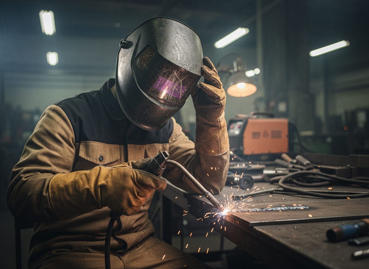
    • Air carbon arc gouging creates heavy sparks, noise, fumes, and intense arc radiation, so helmet shade, hearing protection, gloves, leathers, ventilation, and fire watch matter.
    • Do not use oxygen in place of compressed air for air carbon arc gouging.
    • Always verify carbon electrode size, machine output, cable capacity, and torch condition before blaming the torch body.

    Problem / Context

    Air carbon arc gouging removes metal by melting the workpiece with an arc while compressed air blows the molten metal out of the groove. When the setup is correct, the groove sounds steady and the metal clears forward. When the setup is wrong, the operator may see sputtering, uneven carbon burn-off, wandering arc, violent blowback, undercut edges, shallow wash, or heavy slag left in the gouge.

    This failure can look like a bad torch, but many shops find the cause upstream: air compressor capacity, hose restrictions, undersized welding leads, weak ground clamp contact, wrong carbon diameter, or a welding power source that cannot hold the required amperage under gouging load.

    Root Causes

    1. Air pressure or air volume is too low

    Air carbon arc gouging needs enough compressed air to clear molten metal from the groove. A gauge near the compressor can be misleading if long hoses, small fittings, clogged filters, or quick-connect restrictions reduce flow at the torch. A CSK4000-style torch is commonly listed with an 80 psi pressure requirement and approximately 28 cfm air flow requirement. If the compressor cannot keep up, the arc may still melt the metal, but the air stream will not clear it cleanly.

    2. Carbon electrode size does not match available amperage

    A larger carbon requires more welding current. If the carbon is too large for the machine output, the gouge may chatter, sputter, or only wash the surface. If the carbon is too small for the current, it can overheat and burn back too quickly. Use the torch manufacturerโ€™s amperage range for the carbon diameter instead of guessing from MIG, stick, or plasma settings.

    3. Work clamp contact is weak

    Carbon arc gouging is demanding on the welding circuit. Paint, mill scale, rust, loose clamps, undersized leads, hot cable lugs, or poor terminal connections can create voltage drop. That voltage drop may show up as arc wander, intermittent cutting, excessive spatter, and inconsistent groove depth.

    4. Torch angle or air jet direction is wrong

    The air jet must push molten metal out of the groove, not back toward the operator or sideways across the plate. If the electrode is rotated incorrectly in the jaws, or the torch angle is too steep, the air stream can fight the puddle instead of clearing it. A shallow travel angle with the air directed behind the arc usually gives a smoother groove.

    5. Electrode stickout is excessive

    Too much carbon stickout can make the electrode unstable and increase heating at the torch head. Too little stickout can put the torch too close to heat and molten metal. Verify the recommended stickout in the torch manual and adjust as the carbon burns back.

    6. Torch head, jaws, cable, or air valve are worn

    Worn jaws may not grip the carbon evenly. A damaged cable hose assembly can create heat, air leaks, or poor current transfer. A sticky air valve can delay air flow and leave molten metal in the groove. Inspect the torch before replacing it, especially if the sputter appears only after the torch heats up.

    Solution

    • Verify compressed air at the torch, not only at the compressor. Check pressure under flow and confirm the compressor can support the required cfm.
    • Remove small quick-connect restrictions where possible. Use air hose and fittings sized for gouging flow.
    • Match the carbon electrode diameter to the welding machineโ€™s actual output and duty cycle.
    • Clean the work clamp location to bright metal and tighten all cable lugs.
    • Confirm polarity. Many manual air carbon arc gouging setups commonly use DCEP, but the torch and carbon manufacturer instructions should control.
    • Set the electrode in the jaws so the air jet points in the direction needed to clear molten metal from the groove.
    • Maintain a stable travel angle and steady travel speed. Do not force the carbon into the plate.
    • Stop if the torch handle, cable, or connections become abnormally hot. Heat can indicate overload, poor connection, or damaged components.

    If arc flash risk or lens selection is also part of the shop setup, compare WSPโ€™s welding safety glasses shade and ANSI Z87.1 guide. For TIG shops that also gouge repairs before rewelding, WSPโ€™s best welding helmet for TIG guide can help separate low-amp TIG lens needs from high-intensity gouging needs.

    Specs / Verification Notes

    ItemVerified / CheckpointNotes
    Product typeAir carbon arc gouging torchUsed for heavy metal removal, back-gouging, weld removal, and repair prep.
    ASINB07143B4VPVerified as Weldmark by ArcAir WMK400010 CSK4000 listing on Amazon regional results.
    Arc Weld Store listingVerifiedArc Weld Store lists Weldmark by ArcAir WMK400010 CSK4000 air carbon arc gouging torch.
    Maximum amperageUp to 1000 ampsVerify against the exact torch label, cable assembly, and power source rating before use.
    Air pressure80 psiCommon listing value for CSK4000-style setup. Verify at the torch under flow.
    Air flow28 cfmCommon listing value. Compressor and hose system must support flow continuously.
    Cable assembly length10 ft / 3 mShown in supplier listings for WMK400010 / CSK4000.
    Compatible carbon sizesUnknown (Verify)Use the exact torch manual and carbon manufacturer chart.
    Power source compatibilityUnknown (Verify)Confirm DC output, amperage range, duty cycle, and polarity requirements.

    Product Section

    The Weldmark by ArcAir WMK400010 CSK4000 is a heavy-duty air carbon arc gouging torch option for shops that already have the correct welding power source, compressed air capacity, leads, PPE, and fire-control setup. Verify the exact model, cable length, amperage rating, air requirement, and return policy before ordering.

    Arc Weld Store option: Weldmark By ArcAir WMK400010 - CSK4000 Air Carbon Arc Gouging Torch

    “>Weldmark by ArcAir WMK400010 CSK4000 Air Carbon Arc Gouging Torch

    Weldmark By ArcAir WMK400010 – CSK4000 Air Carbon Arc Gouging Torch
    • 10Ft. (3M) cable assembly
    • Up to 1000 Amps
    • Air Requirements: Pressure: 80 psi (5.6kg/cm2) and Flow Rate: 28cfm (792.4L/Min)
    • Applications: Heavy-Duty Fabrication / Maintenance / Railroad / Shipyard
    • Weldmark by ArcAir

    Last update on 2026-06-26 / Affiliate links / Images from Amazon Product Advertising API

    Comparison Table

    SymptomLikely CauseCheck FirstCorrective Action
    Molten metal does not clearLow air volumeFlow at torch under loadIncrease air supply capacity, remove restrictions, inspect hose and fittings.
    Carbon burns back too fastToo much current or wrong carbon sizeCarbon diameter and amperage chartReduce current or use the proper carbon size.
    Arc wandersPoor work connection or unstable stickoutClamp location, cable lugs, electrode gripClean ground area, tighten leads, reset electrode in jaws.
    Heavy blowbackWrong torch angle or air jet directionElectrode orientation and air jet pathReposition carbon and travel angle so air clears forward.
    Torch gets hotOverload, loose connection, or damaged cableCable assembly, duty cycle, jaw conditionStop use, inspect components, verify machine rating.

    Related Failure Paths

    • Excessive fumes during gouging: usually tied to coating removal, base metal contamination, ventilation limits, or confined-space controls.
    • Arc flash exposure: commonly tied to wrong shade selection, helmet failure, observers without protection, or grinding mode left active on auto-darkening helmets.
    • Hearing exposure: air carbon arc gouging is loud enough that hearing protection should be part of the setup.
    • Fire risk: gouging throws molten metal farther than many welding operations, so sparks can travel behind fixtures, under benches, and into cable piles.

    For helmet-related failures, the WSP post on welding helmets with grind mode is a useful reminder because grind mode discipline matters any time a hood moves between prep work and arc work.

    Safety Notes

    • Use welding helmet filter protection suitable for arc gouging intensity. OSHA eye protection tables list carbon arc welding at shade 14.
    • Wear safety glasses with side shields under the hood when required by shop policy or impact hazard.
    • Use hearing protection. Air carbon arc gouging creates high noise exposure.
    • Use ventilation or respiratory protection appropriate for the material, coating, and workspace. Air carbon arc gouging can produce heavy fumes.
    • Remove combustibles from the spark path and assign fire watch when needed.
    • Never substitute oxygen for compressed air in an air carbon arc gouging setup.
    • Do not service torch, cable, or power connections while energized.

    FAQ

    Why does my gouging torch sputter even though the arc starts?

    The arc can start even when the air stream is too weak to clear molten metal. Check air flow at the torch under load, not just static pressure at the compressor.

    Can a small shop compressor run a CSK4000-style gouging torch?

    Only if it can supply the required pressure and cfm continuously. Supplier listings commonly show 80 psi and 28 cfm for this class of torch, which is beyond many small portable compressors.

    Is sputtering caused by bad carbon rods?

    Sometimes, but carbon size, amperage, air volume, and work connection should be checked first. Damaged, damp, mismatched, or poor-quality carbons can contribute, but they are not the only cause.

    What polarity should air carbon arc gouging use?

    Many manual gouging instructions show DCEP for common setups, but the exact torch, carbon, and power source instructions should be verified before operation.

    What PPE is most often missed during gouging?

    Hearing protection, side-shield eye protection under the hood, respiratory controls, and full flame-resistant coverage are often missed. Gouging throws heavy sparks and produces significant fumes compared with many basic welding tasks.

    Next Step

    Before replacing the torch, test the system in order: compressed air at the torch, carbon size versus amperage, work clamp contact, cable heat, electrode orientation, and PPE readiness. If the CSK4000 is the correct class of torch for the job, confirm the exact WMK400010 listing through Arc Weld Store or the verified ASIN box above.

    Sources Checked

    • Arc Weld Store: Weldmark by ArcAir WMK400010 CSK4000 Air Carbon Arc Gouging Torch listing.
    • Amazon regional listing results for ASIN B07143B4VP.
    • Victor / Arcair K3000 and K4000 manual gouging torch operating manual.
    • AWS air carbon arc gouging safety and technique guide.
    • OSHA 1910.133 eye and face protection standard.
    • OSHA eye protection against radiant energy during welding and cutting fact sheet.
    • AWS Z49.1 Safety in Welding, Cutting, and Allied Processes.
    • Existing WSP posts on welding helmets, welding safety glasses, respirators, and grind-mode helmet selection.
  • MIG Contact Tip Burnback Troubleshooting: Wire Sticking, Fusing, or Melting Back Into the Tip

    MIG contact tip burnback happens when the welding wire melts faster than it is being delivered, then fuses inside the contact tip. The most common causes are wire feed speed too low, stickout too short, a worn or wrong-size contact tip, liner drag, tight gun cable bends, incorrect drive roll pressure, wrong drive roll groove, spool brake drag, or spatter buildup at the nozzle and diffuser. Replace the contact tip first, then check the feed path before changing major machine parts.

    Do not fix repeated burnback by only tightening the drive rolls. Excessive drive pressure can deform solid wire, shave soft wire, pack debris into the liner, and create more feed restriction. Burnback is usually a symptom of unstable wire delivery or incorrect arc length, not just a bad tip.

    Common Symptoms

    SymptomLikely CauseFirst Check
    Wire welded inside contact tipLow wire feed speed, short stickout, feed restrictionReplace tip and straighten gun lead
    Tip glows red or discolorsExcessive heat, loose tip, wrong tip, high duty cycleTighten or replace tip
    Wire feeds, then stops mid-weldLiner drag, spool drag, drive roll slipRemove tip and test feed
    Arc stutters before burnbackWorn tip bore, dirty liner, poor wire contactInstall correct new tip
    Birdnesting after burnbackWire blocked downstream of drive rollsInspect tip, diffuser, liner, and gun cable
    Burnback repeats with new tipsWrong consumable family or feed-path restrictionVerify gun model, liner, wire size, and drive rolls

    Quick Fix: Do This First

    1. Stop welding and turn off the machine before touching the gun front end.
    2. Clip the wire clean near the contact tip.
    3. Remove the nozzle and unscrew the burned contact tip.
    4. Install a new contact tip that matches both the wire diameter and the gun series.
    5. Straighten the gun cable. Avoid tight loops, kinks, and sharp bends.
    6. Jog wire with the tip removed. If feed improves, the old tip was blocked or wrong.
    7. If feed is still rough, check liner drag, drive roll pressure, drive roll groove, and spool brake tension.
    8. Restart with correct stickout and adjust wire feed speed only after the mechanical feed path is stable.

    What This Part Does

    The contact tip transfers welding current to the MIG wire and guides the wire at the exit point of the gun. The tip bore must be the correct size for the wire. Too small can restrict feeding and cause burnback. Too large can reduce electrical contact, allow arc wander, and cause unstable starts. The tip must also match the gunโ€™s thread, length, seating style, and diffuser/retaining head system.

    Root Causes of Contact Tip Burnback

    CauseWhy It Causes BurnbackProper Fix
    Wire feed speed too lowArc consumes wire faster than feeder delivers itIncrease wire feed speed within procedure range
    Stickout too shortArc heat is too close to the tipHold proper contact-tip-to-work distance
    Wrong contact tip sizeWire drags or loses stable electrical contactMatch tip to wire diameter and gun family
    Dirty or kinked linerWire slows, surges, or hesitatesClean or replace liner
    Gun cable bent too tightlyWire friction increases before the tipStraighten cable during test
    Drive roll pressure wrongWire slips or gets crushedReset pressure only tight enough to feed
    Spool brake too tightFeeder motor fights spool dragReduce hub tension until spool stops without overrunning
    Spatter-packed nozzle/diffuserHeat builds up and gas flow becomes unstableClean nozzle and inspect diffuser

    What Wears Out First

    • Contact tip: Replace when the bore is oval, pitted, spatter-packed, loose, overheated, or repeatedly fusing wire.
    • Liner: Replace when wire drags with the tip removed, when changing wire size outside the liner range, or when the gun cable has been kinked.
    • Drive rolls: Clean or replace when the groove is worn, packed with wire shavings, or wrong for solid, flux-cored, or aluminum wire.
    • Diffuser/retaining head: Inspect if tips loosen, overheat, seat poorly, or fail repeatedly.
    • Nozzle: Clean spatter before it traps heat or disrupts shielding gas.

    Compatibility Notes

    Contact tips are not universal. Before ordering, verify the MIG gun brand and series, contact tip thread, tip length, wire diameter, diffuser style, and liner system. A .035 tip for one gun family may not fit another .035 gun. Miller AccuLock MDX, Miller AccuLock S, Lincoln Magnum, Tweco-style, Bernard, Tregaskiss, and ESAB/Tweco systems use different part families depending on gun model.

    Confirmed support pages:

    What To Verify Before Ordering

    • MIG gun model and rear connector type.
    • Wire diameter and wire type.
    • Contact tip part family, thread, length, and bore size.
    • Diffuser or retaining head style.
    • Liner size range and gun cable length.
    • Drive roll groove size and type.
    • Shielding gas and polarity for the process.
    • Whether the gun is original or a replacement gun.

    Common Wrong-Part Mistakes

    • Buying by wire size only instead of gun series.
    • Installing a .030 tip on .035 wire.
    • Using a worn diffuser that no longer seats the tip tightly.
    • Replacing tips repeatedly without checking liner drag.
    • Using excessive drive roll pressure to overcome a blocked liner.
    • Mixing Miller, Lincoln, Tweco, Bernard, and Tregaskiss consumables without confirming thread and seating style.

    Field Fix vs Proper Fix

    ProblemField FixProper Fix
    Wire fused in tipClip wire and replace tipCorrect wire speed, stickout, tip size, and feed path
    Burnback with cable bentStraighten gun leadReplace kinked liner or damaged gun cable
    Tip overheatsLet gun cool and clean nozzleVerify duty cycle, tip seating, diffuser, and settings
    Drive rolls slipReset pressureFix liner drag, roll groove, or spool brake tension
    Repeated burnbackInstall new tipInspect full wire path from spool to tip

    Safety Notes

    Turn off input power before servicing the gun, feeder, liner, or drive rolls. Wear safety glasses when clipping wire or clearing a fused tip. Hot tips and nozzles can burn skin through light gloves. Do not bypass feeder covers, defeat trigger controls, or continue welding with repeated burnback until the restriction is found.

    Sources Checked

    • Weld Support Parts MIG burnback and wire feed troubleshooting pages.
    • Weld Support Parts Miller MDX-100, Lincoln Magnum 100L, and Tweco Fusion gun breakdowns.
    • Bernard/Tregaskiss troubleshooting references for contact tip burnback, worn tips, liner restriction, and wrong tip size.
    • American Torch Tip burnback reference for low wire-feed-speed burnback cause.
  • Welding Cable Connector Compatibility Guide (Dinse, Tweco, Cam-Lok & Stud Types)

    Welding cable connectors are one of the most overlooked compatibility points in a welding setup. A mismatched connector can create overheating, voltage drop, intermittent arc starts, loose cable retention, or complete machine incompatibility.

    This compatibility guide covers the most common welding cable connector types used on MIG, TIG, Stick, plasma, and work lead setups. It focuses on connector identification, fitment verification, amperage considerations, cable sizing, and common wrong-part mistakes.

    Key Takeaways

    • Dinse-style connectors are the most common modern welding connector system.
    • Connector size must match both cable gauge and machine receptacle size.
    • Tweco-style, Cam-Lok, lug, and stud connections are still widely used.
    • Overheated connectors usually indicate loose fitment, undersized cable, or oxidation.
    • Never assume โ€œuniversal fitโ€ for welding cable connectors.
    • Verify polarity style, connector gender, cable size, and amperage rating before ordering.

    What Welding Cable Connectors Do

    Welding cable connectors transfer welding current between the machine, torch, electrode holder, work clamp, or extension leads. They also provide quick disconnect capability for portable welders and field setups.

    A properly matched connector reduces resistance and heat buildup while maintaining stable arc performance. Poor connections increase resistance, which causes overheating, poor starts, unstable arc behavior, and connector damage.

    Common Welding Cable Connector Types

    Connector TypeCommon UseTypical Amperage RangeVerify Before OrderingNotes
    Dinse 10-25Light TIG/StickUp to ~200APlug diameter and cable sizeCommon on inverter welders
    Dinse 35-50MIG/TIG/Stick200Aโ€“400AMachine receptacle sizeMost common shop connector
    Dinse 50-70Industrial welders400A+Cable gauge and machine portHeavy-duty applications
    Tweco-styleOlder MIG/StickVariesThread style and polarity setupStill common in fabrication shops
    Cam-LokEngine drivesHigh amperageMale/female orientationField welding and power distribution
    Stud/LugTransformer weldersVariesBolt size and lug dimensionsOften permanent installations

    Compatibility Notes

    Connector compatibility depends on several factors:

    • Machine connector receptacle size
    • Connector family (Dinse, Tweco, Cam-Lok, Stud)
    • Cable gauge
    • Maximum amperage
    • Polarity configuration
    • Torch or electrode holder compatibility
    • Connector gender/orientation
    • OEM machine design

    Verify machine connector size before ordering. Some inverter welders use smaller Dinse 10-25 ports while industrial machines commonly use 35-50 or larger connectors.

    Some TIG torch kits include 105Z57 or proprietary adapter blocks that may not directly fit every machine. Verify connector configuration before replacing torches or leads.

    Common Symptoms of Incorrect Connector Fitment

    SymptomLikely CauseInspection CheckProper Fix
    Connector overheatingLoose fit or oxidationInspect contact surfacesReplace damaged connector
    Hard arc startsHigh resistance connectionCheck connector seatingClean or replace connector
    Voltage dropUndersized cable or connectorVerify cable gaugeUpgrade cable/connector size
    Intermittent arcLoose locking mechanismInspect twist-lock engagementReplace worn connector
    Burned connector bodyOverloaded amperageCheck duty cycle and amp drawInstall higher-rated connector

    What Usually Wears Out First

    • Connector contact surfaces
    • Twist-lock retention tabs
    • Insulating sleeves
    • Cable strain reliefs
    • Crimped lug terminations
    • Oxidized copper contact points

    Heat cycling and repeated disconnects gradually loosen connector tolerances. Once the fit becomes loose, resistance increases rapidly and connector overheating usually follows.

    Visual Wear Indicators

    • Brown or dark discoloration near contacts
    • Melted insulation
    • Loose connector engagement
    • Visible arcing marks
    • Green corrosion on copper
    • Cracked insulation boots
    • Excessive cable flex near connector

    Inspection Steps

    1. Disconnect power from the welding machine.
    2. Inspect both male and female connector surfaces.
    3. Check for looseness in twist-lock engagement.
    4. Verify cable crimp integrity.
    5. Inspect insulation for heat damage.
    6. Check cable gauge against machine amperage.
    7. Look for oxidation or contamination.
    8. Confirm connector size matches machine receptacle.

    Field Fix vs Proper Fix

    ConditionTemporary Field FixProper Repair
    Loose connector fitClean contactsReplace worn connector
    Minor oxidationLight abrasive cleaningReplace heavily pitted contacts
    Damaged insulationTemporary wrap onlyReplace connector assembly
    Heat discolorationReduce amperage temporarilyInstall correct-rated connector
    Loose crimpUnknown (Verify)Replace/crimp properly

    Common Wrong-Part Mistakes

    • Ordering Dinse 10-25 when machine requires 35-50
    • Using undersized cable with high-amperage connectors
    • Assuming all โ€œDinseโ€ connectors are identical
    • Ignoring connector gender orientation
    • Installing aluminum lugs in high-cycle copper applications
    • Using worn extension connectors with new leads
    • Mixing incompatible aftermarket adapters

    What To Verify Before Ordering

    • Machine make and model
    • Connector family
    • Connector size
    • Cable gauge
    • Maximum amperage
    • Duty cycle requirements
    • Torch or electrode holder style
    • Extension lead compatibility
    • Polarity setup
    • OEM part number

    If unsure, verify connector diameter directly using calipers instead of relying on visual estimation.

    Related Failure Paths

    • Ground clamp overheating
    • Arc instability
    • Excessive voltage drop
    • MIG wire feed surging
    • TIG high-frequency starting issues
    • Burned work leads
    • Damaged machine receptacles
    • Cable insulation failure

    Related Support Articles

    Safety Notes

    • Disconnect machine power before servicing connectors.
    • Never handle overheated connectors without gloves.
    • Loose welding connections can create fire hazards.
    • Inspect connectors regularly in high-duty-cycle environments.
    • Use cable sizes rated for machine output.
    • Follow OSHA and manufacturer electrical safety procedures.

    FAQ

    Are all Dinse connectors interchangeable?
    No. Dinse connectors vary by diameter and amperage class. Verify exact size before ordering.

    Can I use a larger connector on a smaller machine?
    Unknown (Verify). The machine receptacle must physically match the connector.

    Why do my welding cable connectors get hot?
    Heat usually indicates loose fitment, corrosion, undersized cable, or excessive amperage load.

    How often should welding cable connectors be replaced?
    Replacement intervals vary by duty cycle, amperage, environment, and connection frequency.

    Can bad connectors affect weld quality?
    Yes. High resistance connections contribute to unstable arc behavior and voltage drop.

    Next Step

    Before replacing welding leads, torches, or work clamps, verify connector compatibility first. Matching connector family, size, cable gauge, and amperage rating prevents overheating, unstable arc performance, and expensive machine-side damage.

    Sources Checked

    • Manufacturer Dinse connector sizing references
    • OEM welding machine manuals
    • Weld Support Parts support articles
    • AWS welding cable guidance
    • Industry cable sizing charts
  • Why MIG Wire Burns Back Into the Contact Tip

    MIG burnback happens when the welding wire melts into the contact tip instead of feeding cleanly into the weld puddle. It is a common shop problem because the symptom looks simple, but the cause can come from wire speed, stickout, liner drag, contact tip wear, drive roll setup, or grounding.

    This guide focuses on practical troubleshooting for short-circuit MIG welding where the wire repeatedly fuses to the contact tip, stalls at the gun, or creates inconsistent starts.

    Key Takeaways

    • Burnback usually points to the wire melting faster than it is being delivered.
    • Low wire-feed speed, excessive liner drag, worn contact tips, or poor cable setup can all create the same symptom.
    • Do not solve repeated burnback by only increasing drive roll tension. That can deform the wire and create more feeding problems.
    • Contact tips should match the wire diameter and gun system. Unknown compatibility should be verified before ordering.
    • Any troubleshooting should include ventilation, eye protection, gloves, and control of hot work hazards.

    Problem / Context

    The typical sign is a wire end fused inside or at the face of the contact tip. The operator may hear the arc start, snap, and stop. In some cases, the wire birds-nests at the feeder after the wire path blocks at the tip.

    Burnback is not always caused by a bad contact tip. The contact tip is often where the problem becomes visible, but the restriction may be farther back in the gun liner, drive rolls, spool brake, cable bend, or work lead connection.

    Root Causes

    • Wire-feed speed too low: If the arc consumes wire faster than the feeder supplies it, the arc can climb back to the contact tip.
    • Stickout too short: Holding the gun too close reduces the distance between the contact tip and the weld puddle, increasing the chance of burnback.
    • Worn or dirty contact tip: An enlarged, oval, spatter-filled, or wrong-size tip can interrupt smooth wire delivery.
    • Dirty or kinked liner: Debris, metal shavings, or tight bends in the liner increase drag and cause inconsistent feeding.
    • Incorrect drive roll setup: Wrong groove type, wrong groove size, or excessive tension can slip, shave, or deform wire.
    • Gun cable bends: Tight loops or sharp bends make the feeder work harder and can cause wire speed variation at the arc.
    • Poor work connection: A loose or dirty work clamp can destabilize the arc and make starts less predictable.
    • Burnback control setting: Some machines have adjustable burnback timing. Incorrect adjustment can leave the wire too short after trigger release.

    Solution

    Start with the simplest checks before replacing multiple parts. Clip the wire clean, install a known-good contact tip that matches the wire diameter, and confirm the wire feeds through the gun without unusual resistance.

    1. Confirm the contact tip size matches the wire being used.
    2. Check the machine settings against the wire size, material thickness, shielding gas, and transfer mode.
    3. Increase wire-feed speed slightly if the wire is burning back immediately at arc start.
    4. Hold a consistent contact-tip-to-work distance instead of pushing the nozzle too close to the puddle.
    5. Remove the contact tip and feed wire through the gun. If feeding improves, replace the tip.
    6. If resistance remains with the tip removed, inspect the liner, gun cable bends, and feeder path.
    7. Check drive roll size, groove type, pressure, and wire spool brake tension.
    8. Clean the work clamp area and confirm the work lead connection is tight.
    9. Review burnback timer settings only after the mechanical feeding path is confirmed.

    Specs / Verification Notes

    Item to VerifyWhy It MattersStatus
    Wire diameterContact tip and drive roll groove must match the wire size.Unknown (Verify)
    Contact tip thread/systemTips are not universal across all MIG guns.Unknown (Verify)
    Liner sizeA liner that is too small, worn, kinked, or contaminated can create drag.Unknown (Verify)
    Drive roll grooveSolid wire commonly uses V-groove rolls; cored wire often uses knurled rolls.Unknown (Verify)
    Burnback timerSome MIG machines include adjustable burnback timing.Unknown (Verify)

    Product Section

    The product below was checked as an Amazon listing with a visible ASIN. Confirm wire diameter, thread style, gun compatibility, and seller details before purchase.

    Comparison Table

    SymptomLikely AreaCheck First
    Wire fuses to tip immediatelyWire-feed speed or stickoutIncrease wire feed slightly and maintain proper gun distance.
    Wire feeds unevenly before burnbackLiner, drive rolls, spool brakeInspect the full wire path for drag or slipping.
    Tip hole looks oval or spatteredContact tip wearReplace with the correct size tip.
    Bird-nesting at feederBlocked path near gun or tipRemove the tip and test wire feed through the gun.
    Arc starts harsh or unstableWork connection or settingsClean the work clamp area and verify voltage and wire-feed settings.

    Safety Notes

    Follow ANSI Z49.1 guidance for welding, cutting, and allied processes. Use appropriate eye, face, hand, and body protection, and keep the work area controlled for sparks, heat, and fire hazards.

    AWS safety guidance also emphasizes adequate ventilation for welding and cutting. Keep the breathing zone out of the fume plume and use local exhaust or other controls where required.

    Disconnect power according to the equipment manual before servicing feeder components, gun liners, or internal machine parts. Hot contact tips and nozzles can cause burns even after welding stops.

    FAQ

    Does burnback always mean the contact tip is bad?

    No. A worn or dirty contact tip can cause burnback, but liner drag, low wire-feed speed, tight cable bends, incorrect drive rolls, or a poor work connection can also cause the same symptom.

    Should drive roll tension be increased when burnback happens?

    Only after checking the rest of the wire path. Too much drive roll tension can deform the wire, create metal shavings, and make liner contamination worse.

    Can stickout cause burnback?

    Yes. If the contact tip is held too close to the weld puddle, the arc has less wire length between the tip and the work. That can increase burnback risk, especially during starts and stops.

    How often should MIG contact tips be replaced?

    There is no single replacement interval for every shop. Replace the tip when the bore is worn, oval, spatter-blocked, feeding becomes inconsistent, or arc starts become unreliable.

    Can burnback timing fix the problem?

    Sometimes, but only after confirming the mechanical feed path is correct. Burnback timing should not be used to hide a worn tip, dirty liner, or incorrect drive roll setup.

    Next Step

    For repeated MIG burnback, replace the contact tip with the correct size, straighten the gun cable, test wire feed with the tip removed, and inspect the liner if resistance remains. Verify consumable compatibility before ordering replacement tips.

    Sources Checked

    • Amazon product listing checked for ASIN B0GG66ZVBD.
    • American Torch Tip: causes of contact tip burnback.
    • Hobart Brothers: common wire feeding issues and contact tip wear.
    • General Air: wire feeding problems, liners, contact tips, drive rolls, and welding circuit checks.
    • AWS ANSI Z49.1 safety guidance for welding, cutting, and allied processes.
    • AWS Safety and Health Fact Sheet: ventilation for welding and cutting.
  • Plasma Cutter Not Cutting Through: Causes and Fixes

    A plasma cutter that fails to cut through material typically indicates issues with air supply, consumables, or machine setup. This problem reduces cut quality, increases dross, and can damage the torch if ignored. Diagnosing the root cause quickly restores performance and prevents unnecessary wear.

    Key Takeaways

    • Insufficient air pressure is a leading cause of poor cutting performance
    • Worn consumables reduce arc energy and cut penetration
    • Incorrect amperage settings limit cutting capability
    • Slow or inconsistent travel speed affects cut-through
    • Moisture in air supply degrades plasma arc quality

    Problem / Context

    Plasma cutting relies on a high-temperature ionized gas stream to melt and eject metal. When any part of the systemโ€”air supply, power, or consumablesโ€”is compromised, the arc loses effectiveness. This results in incomplete cuts, excessive slag, or arc instability.

    Root Causes

    • Low air pressure: insufficient airflow reduces arc force
    • Moisture contamination: water in air disrupts plasma stability
    • Worn consumables: degraded electrodes and nozzles reduce performance
    • Incorrect amperage: not matched to material thickness
    • Slow travel speed: excessive heat buildup without full penetration
    • Poor ground connection: unstable arc behavior

    Solution / Explanation

    • Verify air pressure meets machine specifications
    • Install air dryers or filters to remove moisture
    • Replace consumables regularly based on wear
    • Adjust amperage according to material thickness
    • Maintain consistent travel speed during cutting
    • Ensure clean and secure ground clamp connection

    Specs / Verification Notes

    • Air Pressure: Unknown (Verify per machine manual)
    • Amperage Range: Machine dependent
    • Consumable Life: Usage dependent
    • Cut Thickness Capacity: Unknown (Verify)
    • Air Quality Requirement: Dry, oil-free air

    Comparison Table

    CauseSymptomImpactFix
    Low Air PressureWeak arcNo full cut-throughIncrease pressure
    Worn ConsumablesWide arcPoor cut qualityReplace parts
    Moisture in AirArc sputteringInconsistent cutsDry air supply
    Low AmperageSlow cuttingIncomplete penetrationIncrease output

    Safety Notes

    Follow ANSI Z49.1 safety standards for plasma cutting. Ensure proper grounding and use appropriate PPE including eye protection and gloves. Never operate a plasma cutter with damaged consumables or unstable air supply.

    FAQ

    Why is my plasma cutter not cutting all the way through?

    This is usually caused by low air pressure, worn consumables, or incorrect amperage settings.

    Can bad air quality affect plasma cutting?

    Yes. Moisture or oil in the air supply disrupts the plasma arc and reduces cutting efficiency.

    How often should consumables be replaced?

    Replacement depends on usage and material, but worn consumables should be changed as soon as cut quality declines.

    Next Step

    Check air supply quality and consumable condition before the next cut. Adjust settings based on material thickness and confirm stable operation on scrap material.

    Sources Checked

    • ANSI Z49.1 Safety in Welding and Cutting
    • Plasma cutter manufacturer’s operation manuals
    • AWS cutting process references (general guidance)
  • Oxy-Acetylene Torch Backfire vs Flashback: Causes and Fixes

    Backfire and flashback events in oxy-acetylene torches indicate improper gas flow, tip condition issues, or unsafe operating practices. While a backfire is typically a momentary pop, a flashback is more serious and can travel into the torch or hoses, creating a significant safety hazard.

    Key Takeaways

    • Backfire is a short pop; flashback is a sustained flame reversal
    • Dirty or damaged tips are a common cause
    • Incorrect gas pressures disrupt flame stability
    • Blocked hoses or regulators increase flashback risk
    • Flashback arrestors are critical safety components

    Problem / Context

    Oxy-fuel systems rely on controlled gas flow and proper mixing at the torch tip. When this balance is disrupted, combustion can occur inside the tip or travel backward into the system. Understanding the difference between backfire and flashback is essential for safe troubleshooting and prevention.

    Root Causes

    • Clogged or dirty tip: restricts gas flow and causes unstable combustion
    • Incorrect gas pressure: improper oxygen-to-fuel ratio
    • Loose tip or connections: creates internal leaks
    • Overheating tip: increases risk of ignition inside the tip
    • Blocked hoses or regulators: restricts flow and pressure stability
    • Missing flashback arrestors: no protection against reverse flame travel

    Solution / Explanation

    • Clean torch tips using proper tip cleaners sized for the orifice
    • Verify gas pressures match manufacturer recommendations
    • Tighten all connections securely before operation
    • Allow the torch to cool if overheating occurs
    • Inspect hoses and regulators for restrictions or damage
    • Install and maintain flashback arrestors on both oxygen and fuel lines

    Specs / Verification Notes

    • Operating Pressure (Oxygen): Unknown (Verify)
    • Operating Pressure (Acetylene): Unknown (Verify)
    • Tip Size: Application dependent
    • Flashback Arrestor Rating: Unknown (Verify)
    • Hose Type: Grade R or T (application dependent)

    Comparison Table

    ConditionSymptomSeverityCorrection
    BackfireLoud pop, flame extinguishesLowClean tip, adjust pressure
    FlashbackHissing or whistling, flame inside torchHighClean or replace the tip
    Clogged TipUnstable flameMediumHissing or whistling, flame inside the torch
    Low Gas PressureWeak or sputtering flameMediumAdjust regulator settings

    Safety Notes

    Follow ANSI Z49.1 and CGA safety guidelines for oxy-fuel systems. Always use flashback arrestors and check valves. Shut off the gas supply immediately if a flashback is suspected. Never operate damaged equipment.

    FAQ

    What is the difference between backfire and flashback?

    Backfire is a brief pop with flame extinguishing, while flashback involves flame traveling back into the torch or hoses.

    What should be done during a flashback?

    Immediately shut off oxygen first, then fuel gas, and inspect the system before reuse.

    Can dirty tips cause flashback?

    Yes. Restricted gas flow from clogged tips is a common trigger for both backfire and flashback.

    Next Step

    Inspect the torch system, clean the tip, and verify gas pressures before next use. Install flashback arrestors if not already present to reduce risk.

    Sources Checked

    • ANSI Z49.1 Safety in Welding and Cutting
    • CGA (Compressed Gas Association) safety guidelines
    • Oxy-fuel torch manufacturer manuals (general reference)
  • Stick Welding Rod Sticking: Causes and How to Fix It

    When your stick electrode keeps sticking to the workpiece, it usually means the arc isnโ€™t stable enough to stay lit. This is one of the most common frustrations in stick welding and is typically caused by low amperage, poor technique, or improper setup.

    Key Takeaways

    • Rod sticking is usually caused by low amps or weak arc starts
    • Correct amperage and arc length are critical
    • Moisture and rod condition can affect performance
    • Technique (especially arc striking) plays a big role

    Whatโ€™s Causing the Problem

    1) Amperage Too Low

    • Not enough heat to maintain the arc
    • The electrode fuses to the base metal instead of melting properly

    2) Poor Arc Start Technique

    • Tapping too lightly or dragging incorrectly
    • Not establishing a strong initial arc

    3) Incorrect Arc Length

    • Holding the rod too close chokes the arc
    • Too far causes instability and extinguishing

    4) Damp or Contaminated Rods

    • Moisture affects arc stability and slag formation
    • Especially common with 7018 rods

    5) Improper Ground Connection

    • Weak or inconsistent electrical circuit
    • Causes erratic arc behavior

    How to Fix It

    Step 1: Increase Amperage

    • Adjust amps based on rod size:
      • 1/8″ (3.2 mm) rod โ†’ ~90โ€“130 amps
    • Start in the middle of the range and adjust as needed

    Step 2: Improve Arc Start

    • Use a scratch or tap method with confidence
    • Strike the arc like lighting a match, then lift slightly

    Step 3: Maintain Proper Arc Length

    • Keep arc length about equal to rod diameter
    • Too short = sticking
    • Too long = unstable arc

    Step 4: Use Dry Electrodes

    • Store rods in a dry environment
    • Use a rod oven for low-hydrogen electrodes (like 7018)

    Step 5: Check Ground Clamp

    • Attach to clean, bare metal
    • Ensure a tight connection

    Common Mistakes to Avoid

    • Running amps too low โ€œto be safe.โ€
    • Hesitating during arc start
    • Welding with damp rods
    • Ignoring poor ground connections
    • Holding too tight or an inconsistent arc length

    Best Settings / Guidelines

    ParameterTypical Range
    Amperage90โ€“130A (1/8″ / 3.2 mm rod)
    Arc LengthEqual to rod diameter
    Rod ConditionDry, properly stored
    Ground ContactClean, solid connection
    Travel SpeedModerate, consistent

    Always verify amperage with rod manufacturer recommendations.

    Safety Notes

    • Wear proper eye protection (ANSI Z87.1) and welding helmet
    • Stick welding produces significant fumesโ€”ensure ventilation
    • Keep gloves dry to avoid shock risk
    • Inspect electrode holder and cables for damage

    FAQ

    Why does my rod stick immediately when I strike an arc?
    Usually due to low amperage or poor arc start technique.

    Can moisture really affect stick welding?
    Yesโ€”especially with low-hydrogen rods like 7018.

    Whatโ€™s the best rod for beginners?
    6013 is more forgiving and easier to start than 7018.

    Does polarity matter for sticking?
    Yesโ€”incorrect polarity can cause poor arc stability.

    Should I increase amps if my rod sticks?
    Yesโ€”slightly increasing amperage often solves the issue.

    Sources Checked

    • American Welding Society
    • Lincoln Electric stick welding guides
    • Miller Electric setup and troubleshooting resources

  • Why Your TIG Weld Is Getting Contaminated (And How to Fix It)

    TIG contamination shows up as a dull, dirty weld, unstable arc, or blackened tungsten. Itโ€™s usually caused by poor shielding, dirty material, or tungsten issues, and it will quickly ruin weld quality if not corrected.

    Key Takeaways

    • Contamination is usually caused by air exposure or dirty surfaces
    • Tungsten condition directly affects arc stability
    • Shielding gas problems are a top cause
    • Cleanliness is critical for TIG welding success

    Whatโ€™s Causing the Problem

    1) Poor Shielding Gas Coverage

    • Gas flow is too low or disrupted
    • Drafts pulling shielding gas away
    • Leaks in hoses or fittings

    2) Dirty Base Material

    • Oil, grease, oxidation, or coatings
    • The aluminum oxide layer was not removed
    • Stainless contamination from improper tools

    3) Contaminated Tungsten

    • Touching the puddle or filler rod
    • Improper grinding direction
    • Using the wrong tungsten type for the job

    4) Incorrect Gas Flow Settings

    • Too low โ†’ inadequate shielding
    • Too high โ†’ turbulence pulling in air

    5) Bad Technique

    • Long arc length exposing the weld to the atmosphere
    • Improper torch angle
    • Inconsistent filler rod feeding

    How to Fix It

    Step 1: Set Proper Gas Flow

    • Typical range: 15โ€“25 CFH (7โ€“12 L/min)
    • Use lower end indoors, higher if needed for coverage

    Step 2: Clean the Material Thoroughly

    • Use a dedicated stainless steel brush for aluminum/stainless steel
    • Remove all oil and grease with acetone
    • Grind or wire brush to clean the metal surface

    Step 3: Prepare Tungsten Correctly

    • Grind longitudinally (not around)
    • Keep a sharp, clean point for DC welding
    • Replace tungsten if contaminated

    Step 4: Check Equipment

    • Inspect gas lines and connections for leaks
    • Clean the nozzle and check the gas lens if installed
    • Ensure proper cup size for coverage

    Step 5: Improve Technique

    • Keep arc length short and consistent
    • Maintain proper torch angle (~10โ€“15ยฐ)
    • Feed the filler rod smoothly without touching the tungsten

    Common Mistakes to Avoid

    • Welding on dirty or oxidized metal
    • Letting tungsten touch the weld puddle
    • Running gas flow too high or too low
    • Using contaminated filler rods
    • Ignoring drafts in the work area

    Best Settings / Guidelines

    ParameterTypical Range
    Gas Flow15โ€“25 CFH (7โ€“12 L/min)
    Arc LengthShort and consistent
    Torch Angle10โ€“15ยฐ
    Tungsten PrepSharp point (DC), clean grind
    Filler RodClean, matched to material

    Always verify with your machine settings and material requirements.

    Safety Notes

    • Wear proper eye protection (ANSI Z87.1) and a welding helmet
    • Avoid breathing shielding gas in confined areas
    • Use proper ventilation when cleaning with solvents
    • Keep gloves clean to prevent contaminating filler rods

    FAQ

    Why does my tungsten turn black?
    This usually indicates poor shielding gas coverage or contamination.

    Can I reuse contaminated tungsten?
    Yes, but it must be re-ground properly before reuse.

    Does gas type matter for contamination?
    Yesโ€”pure argon is standard for TIG and provides proper shielding.

    Why is aluminum more prone to contamination?
    Aluminum forms an oxide layer that must be removed before welding.

    Can drafts really affect TIG welding?
    Yesโ€”even small air movement can disrupt shielding gas.

    Sources Checked

    • American Welding Society
    • Lincoln Electric TIG welding resources
    • Miller Electric application and troubleshooting guides

  • Plasma Cutter Wonโ€™t Pierce Metal: Causes and Fixes

    A plasma cutter that fails to pierce metal will produce arc instability, excessive spatter, or no full penetration. This issue is typically related to air supply, consumable wear, or incorrect setup parameters. Identifying the restriction point in the system is critical for restoring proper cut initiation.

    Key Takeaways

    • Insufficient air pressure is a leading cause of failed pierce
    • Worn consumables disrupt arc focus and energy transfer
    • Incorrect amperage or travel setup prevents full penetration
    • Material thickness must match machine capability

    Problem / Context

    Plasma cutting relies on a high-velocity ionized gas stream to melt and eject metal. When the system cannot pierce, the arc may start but fail to transfer enough energy into the material. This results in surface gouging instead of a full cut-through.

    Root Causes

    • Low air pressure or flow: weak arc and poor metal ejection
    • Moisture in air supply: destabilizes plasma arc
    • Worn electrode or nozzle: reduces arc concentration
    • Incorrect amperage setting: insufficient heat input
    • Excessive stand-off distance: arc loses intensity before contact
    • Material too thick: exceeds machine rating

    Solution / Explanation

    • Verify air compressor output meets cutter requirements (pressure and CFM)
    • Install a moisture separator or dryer to remove water contamination
    • Inspect and replace consumables if wear is visible
    • Set amperage appropriate to material thickness
    • Maintain correct torch height during pierce and cut
    • Confirm material thickness is within rated capacity

    Specs / Verification Notes

    • Air Pressure Requirement: Unknown (Verify)
    • Air Flow (CFM): Unknown (Verify)
    • Amperage Range: Machine dependent
    • Maximum Pierce Thickness: Unknown (Verify)
    • Consumable Type: Model-specific

    Comparison Table

    IssueSymptomCorrection
    Low Air PressureWeak arc, no penetrationIncrease PSI/CFM
    Worn ConsumablesWide arc, spatterReplace electrode/nozzle
    Moisture in AirArc instabilityAdd dryer/filter
    Incorrect SettingsIncomplete pierceAdjust amperage

    Safety Notes

    Follow ANSI Z49.1 for safe cutting practices. Ensure proper ventilation and use appropriate eye and face protection rated for plasma cutting. Disconnect power before servicing consumables or air systems.

    FAQ

    Why wonโ€™t my plasma cutter pierce thick steel?

    The material may exceed the machineโ€™s rated pierce capacity or settings may be too low.

    Does air pressure affect piercing?

    Yes. Low pressure reduces arc force and prevents molten metal from being expelled.

    How often should consumables be replaced?

    Replace when wear is visible or cut quality declines. Frequency depends on usage and material.

    Next Step

    Check air supply and inspect consumables before the next cut. Correct setup and maintenance resolve most piercing failures without equipment changes.

    Sources Checked

    • ANSI Z49.1 Safety in Welding and Cutting
    • Plasma cutter manufacturer manuals (general reference)
    • Air compressor and filtration guidelines
  • Why You Can’t See Your Weld Pool (And How to Fix It)

    Why You Can’t See Your Weld Pool (And How to Fix It)

    Your helmet lens is probably dirty, scratched, or damagedโ€”and it’s costing you quality welds.

    If you’re squinting through your helmet or struggling to see the puddle clearly, the problem isn’t your eyesight. It’s your lens. Dirty, scratched, or worn lenses block light and create a hazy view that makes precision impossible. The good news: this is an easy fix.

    Symptoms of a Bad Helmet Lens

    • Hazy or cloudy view even in good light
    • Scratches or scuffs visible on the lens surface
    • Difficulty seeing the weld pool or joint
    • Lens feels sticky or has residue buildup
    • Darkening is uneven or inconsistent across the lens
    • You’re lifting your helmet more often to see clearly

    Why This Happens

    Welding helmets take a beating. Spatter, grinding dust, and UV exposure degrade the lens over time. The outer clear lens (the protective layer) scratches easily from handling and contact with metal. The inner auto-darkening filter (if you have one) can accumulate dust and residue, especially in high-spatter processes like MIG.

    Even small scratches refract light and reduce contrast, making it harder to follow your bead. Residue from flux, spatter, or shop dust acts like a filter, dimming your view and forcing you to compensate by tilting your head or adjusting your shadeโ€”both bad habits that slow you down.

    AWS D1.1 welding standards don’t specify lens cleanliness, but they do require clear, undamaged optics for safe, quality welds. A damaged lens compromises both.

    The Fix (Step-by-Step)

    Step 1: Clean the lens thoroughlyStart with the outer clear lens. Use a soft, lint-free cloth and warm water with a drop of mild soap. Wipe gentlyโ€”don’t scrub. Dry completely. For the inner auto-darkening filter, use a dry cloth only (water can damage the LCD).

    Step 2: Inspect for damageHold the lens up to light. Look for scratches, cracks, or discoloration. If you see deep scratches or cracks, the lens needs replacement. Small surface scratches won’t affect visibility much, but they’ll get worse.

    Step 3: Replace if necessaryIf cleaning doesn’t help, order replacement lenses. Most helmets use standard sizes: outer clear lenses (usually 4.5″ x 5.25″ or similar) and inner filters (if auto-darkening). Check your helmet model or measure the lens.

    Step 4: Install the new lensMost helmets have a simple snap-in or screw-on design. Remove the old lens, snap or screw in the new one. Takes 30 seconds.

    Step 5: Test before weldingStrike a test arc or wave the helmet at a light source. The lens should darken instantly and evenly. If it doesn’t, check the battery (for auto-darkening) or reinstall the lens.

    Real-World Tip

    Experienced welders replace outer clear lenses every 2โ€“3 months in high-spatter environments (MIG, flux-core). It’s cheap insurance. Keep a spare pack of lenses in your toolbox. When visibility drops, swap them out immediately instead of fighting through a bad lens. You’ll weld faster and straighter.

    Safety Note

    ANSI Z87.1 requires helmets to have impact-resistant lenses and proper UV/IR protection. A cracked or heavily scratched lens fails this standard and puts your eyes at risk. Replace damaged lenses before your next weld.

    Next Steps

    If this keeps happening, your helmet lens is likely worn or damaged. See the best replacement options โ†’  Best Welding Helmet Replacement Lenses for Clear Visibility 

  • Try Amazon Prime Free