Tag: welding accessories
-
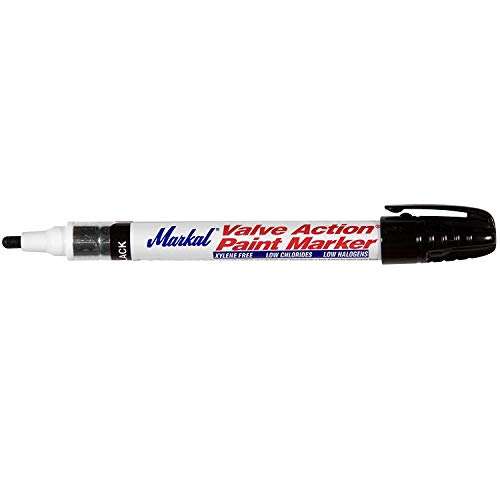
Markal 96823, Valve Action Black Paint Marker, Pack of (1): Product Breakdown
“>
The Markal 96823, Valve Action Black Paint Marker, Pack of (1) is a shop marking tool for layout, identification, and field marking where a standard ink marker is not enough. The product information provided identifies it as a real paint marker with valve action, a replaceable fiber nib, and a stated dry time of about 3 minutes. For welders, fabricators, and maintenance teams, the main value is simple: a marker that lays down visible paint on work surfaces and is built for repeated use.
Key Takeaways
- Valve action releases paint as needed for continuous marking.
- The marker uses real paint, not standard pen ink.
- Stated dry time is 3 minutes.
- Lead-free and low halogens are listed features.
- The fiber nib is replaceable, which supports full use of the marker body.
- Overall product weight is listed as 0.1 pounds.
Where this marker fits in a welding and fabrication shop
A black paint marker is generally used for part identification, cut lines, fit-up notes, and general shop marking on surfaces where visibility matters. The valve-action design helps control paint flow, which is useful when marking long runs or repeated notes. If you need a mark that stays visible through handling, the real-paint format is usually more practical than a standard felt-tip marker.
This is not a process-control device. It does not approve materials, procedures, or weld parameters. Use it as a shop marking tool only.
Check, inspect, verify before use
- Check the surface: Verify the material is suitable for paint marking. Clean, dry surfaces usually give better visibility. Unknown (Verify) on adhesion to coated, oily, or heavily oxidized surfaces.
- Inspect the nib: Make sure the fiber nib is present, seated, and not damaged before first use.
- Verify flow: Test on scrap or a non-critical area to confirm paint release before marking production parts.
- Check drying time: The stated dry time is 3 minutes, but actual dry time can vary with surface condition, film thickness, temperature, and airflow. Verify on your actual work surface.
- Inspect for contamination: If the marker has been stored open or in a dirty area, verify the nib is not clogged before relying on it for layout.
Troubleshooting and support
If the marker does not perform as expected, use a simple inspection sequence before replacing it.
- No paint transfer: Check that the nib is fully engaged. Then verify the tip is primed per normal paint-marker practice. If flow does not start, inspect for clogging or drying at the nib.
- Weak or uneven line: Verify the surface is not dusty, oily, or excessively rough. Inspect the nib for wear. The replaceable fiber nib is intended to support continued use once the tip wears.
- Excessive paint release: Check whether the marker is being pressed too hard. Valve-action markers are meant to release paint as needed; too much pressure can flood the line.
- Poor visibility: Verify the base material color and finish. Black paint may be difficult to read on dark or contaminated surfaces.
Handling and use notes
The listed features suggest a marker designed for straightforward manual use in the shop or field. Because it is a paint marker, treat it as a consumable that can dry out if left uncapped or handled incorrectly. Keep the cap secured when not in use. If the nib becomes worn, the replaceable tip supports continued use without discarding the entire body immediately.
Use the marker for identification and layout only. Do not assume the mark remains permanent under grinding, blasting, heat, solvent exposure, or weather. Unknown (Verify) on resistance to these conditions because no additional performance data was provided.
Product and parts notes
Provided product information for the Markal 96823 identifies these details:
- Product type: Marker
- Category: Paint
- Marker style: Valve action
- Nib: Fiber nib, replaceable
- Paint type: Real paint
- Lead status: Lead-free
- Halogens: Low halogens
- Dry time: 3 minutes
- Overall product weight: 0.1 pounds
Any use beyond those statements should be treated as Unknown (Verify). Do not assume surface chemistry, temperature limits, or chemical resistance without a current manufacturer data sheet or direct product confirmation.
Safety notes
- Use the marker in a ventilated area if you are sensitive to paint odors.
- Avoid skin and eye contact with wet paint.
- Keep away from ignition sources unless the manufacturer documentation states otherwise. Unknown (Verify) on flammability details.
- Do not mark parts where paint contamination is prohibited without verifying downstream process requirements.
- Follow local shop rules for solvent, paint, and waste handling.
FAQ
Is the Markal 96823 a standard ink marker?
No. The provided product information identifies it as a real paint marker with valve action.Can it be used on any metal surface?
Unknown (Verify). Surface condition matters, and no full compatibility list was provided. Test on scrap or a non-critical area first.Does the marker dry fast enough for shop use?
The stated dry time is 3 minutes. Actual dry time can change based on surface, film thickness, and environment, so verify on the part being marked.Can the nib be replaced?
Yes. The provided information states that the fiber nib is replaceable.Sources Checked
- ArcWeld product page: Markal 96823, Valve Action Black Paint Marker, Pack of (1)
- Provided product summary fields for features and dimensions
Related Arc Weld Part
Markal 96823, Valve Action Black Paint Marker, Pack of (1)
434-96823 Features: -Marks with real paint, dries in 3 minutes. -Nib releases paint as needed for continuous marking. -Lead-free, low halogens. -The fiber nib is replaceable to assure complete use of each marker. Product Type: -Markers. Category: -Paint. Dimensions: Overall Product Weight: -0.1 Pounds.
View at Arc Weld Store
Markal 96270, Silver Steak Markal PRO Holder, Pack of (1): Replacement Part Breakdown
The Markal 96270, Silver Steak Markal PRO Holder, Pack of (1) is best treated as a consumable support item in a marking system, not as a standalone process-critical welding component. For maintenance buyers, shop leads, and support teams, the main question is simple: when a holder starts to fail, what should you inspect before you replace it, and what should you verify after it arrives?
This guide breaks the part down from a service and support angle. It does not assume undocumented compatibility, dimensions, or internal construction details. Where technical details are not confirmed here, they are listed as Unknown (Verify).
Key Takeaways
- The Markal 96270 listing identifies a replacement holder item, but exact internal build details are Unknown (Verify).
- Before ordering a replacement, inspect the current holder for wear, binding, cracked body parts, or poor lead/marking retention.
- After receipt, verify fit, actuation, retention, and general condition before putting it into service.
- Do not assume compatibility with other Markal holders or marking formats unless confirmed by the seller or your internal part records.
- Use the Amazon product listing only as a product reference point; do not rely on it for undocumented repair guidance.
What This Part Is Used For
The product name indicates a Markal PRO holder associated with Silver Steak marking use. In practice, holders in this category are used to secure and present a marking stick or similar consumable in a controlled way. The exact operating method for this specific unit is Unknown (Verify), so support teams should confirm the current tool design before attempting repair, disassembly, or substitution.
If the holder is being used in a fabrication or maintenance environment, common failure symptoms include poor retention, inconsistent feed, damaged locking features, or a body that no longer holds alignment. Those symptoms do not prove the holder is the only problem. The marking stick, operator handling, storage conditions, or contamination can also be involved.
Inspection Checklist Before Replacement
Use this sequence before writing off the holder:
- Inspect the body. Look for cracks, bent sections, gouges, or heat damage.
- Check retention surfaces. Verify the part still grips the marking material consistently.
- Check movement. If the holder has a sliding or advancing function, verify it moves without sticking.
- Inspect for debris. Clean out dust, metal fines, and marker residue.
- Verify operator handling. Check whether the tool is being dropped, over-tightened, or stored in a way that causes premature wear.
If any of these checks fail, document the condition with photos and note whether the problem is intermittent or continuous. That record helps avoid repeating the same failure after replacement.
Troubleshooting Support Steps
1) Holder will not retain the marking stick
Check: Confirm the stick type matches the holder’s intended size and format. Exact fit data is Unknown (Verify).
Inspect: Look for worn jaws, damaged guides, or missing internal parts.
Verify: Test with a known good marking stick from the same inventory lot if available.
2) Advancement feels stiff or inconsistent
Check: Make sure the unit is not loaded with broken fragments or compacted dust.
Inspect: Examine sliding interfaces for contamination, bending, or corrosion.
Verify: Clean the holder and repeat the movement test before replacing the unit.
3) Marking quality has declined
Check: Confirm the issue is not in the marking material itself.
Inspect: Review the tip presentation and whether the holder is keeping the stick aligned.
Verify: Compare output against a known good holder under the same operator and surface conditions.
Product and Parts Notes
The only confirmed product detail provided here is the Amazon ASIN reference for the Markal 96270, Silver Steak Markal PRO Holder, Pack of (1): B074WGYF21. No additional specifications, dimensions, or repair kits are verified in the source data available for this draft.
If you are building a replacement-part record, capture the following internally:
- Original part name and ASIN reference
- Observed failure mode
- Date removed from service
- Any matching model or lot data from packaging
- Operator notes on fit, feel, and performance
Do not assume a “similar” holder will work as a direct substitute unless the vendor or your own verified records confirm it.
Support and Ordering Considerations
For buyers, the main risk is ordering on description alone. The product title suggests a specific Markal PRO holder variant, but the available source data does not confirm cross-compatibility with other holder bodies, refill formats, or accessories. Keep that uncertainty in the purchase record and verify against your own approved-use list before standardizing the part.
If the existing holder is failing repeatedly, review the root cause before replacement. Storage, contamination, impact damage, and incorrect loading are common contributors in marking tool service problems. A replacement part will not fix a handling issue.
Safety Notes
- Wear appropriate hand protection when inspecting used marking tools with sharp or worn edges.
- Do not force a jammed mechanism apart unless the tool design and service method are confirmed.
- Keep solvents, compressed air, and cleaning methods compatible with your site procedures.
- Remove the holder from service if cracks, breakage, or loose internal parts are found.
- Use lockout, housekeeping, and tool-control practices where required by site policy.
FAQ
Is this a complete tool or a replacement support part?
The product name indicates a holder product. Exact internal configuration is Unknown (Verify), so confirm whether your application treats it as a complete tool, a replacement component, or a consumable support item.
Can I use it with other Markal products?
Not enough verified data is available here to confirm compatibility. Treat compatibility as Unknown (Verify) unless your internal part records or the seller confirm it.
What should I check before buying a replacement?
Inspect the existing holder for wear, binding, damage, and contamination. Verify the marking material type, the loading method, and any model identifiers from the old unit before placing an order.
What if the new holder still does not work properly?
Verify the marking stick or consumable, the loading method, and the operator technique. If the failure repeats, document the issue and compare the new part against the removed part for fit and function.
Sources Checked
- Amazon product reference provided in the task: Markal 96270, Silver Steak Markal PRO Holder, Pack of (1), ASIN B074WGYF21
- No WSP lookup page provided
- No filler metal finder page provided
- No internal links provided
Note: This draft intentionally avoids unverified specifications, pricing, certifications, and compatibility claims. Use internal records or supplier confirmation to complete any unresolved technical details.
Matched Replacement Option
No products found.
Disclosure: As an Amazon Associate, Weld Support Parts may earn from qualifying purchases.
Markal 96100 Red-Riter Welders Pencil for Torch-Resistant Marks During Metal Layout and Fabrication, Red (Pack of 12) Made in USA: Replacement Part Breakdown
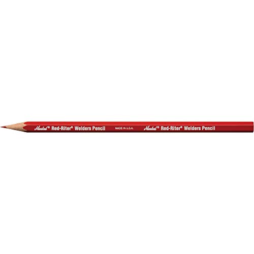
Layout marks are part of the job. If the line is wrong, the cut is wrong, the fit-up is wrong, and the time loss shows up fast. The Markal 96100 Red-Riter Welders Pencil is used for metal layout and fabrication marking where a durable visible line is needed. For buyers and shop teams, the main question is not whether it writes. The question is what it does well, what it does not do, and how to verify it matches the job before you buy in quantity.
Key Takeaways
- Use this type of marking pencil for layout work where standard shop markers may fail or become hard to read.
- Confirm the marking surface, visibility, and cleanup method before using it on production parts.
- Do not assume torch resistance or heat survival on every alloy, coating, or process without testing.
- Pack quantity, packaging, and origin are provided by the listing; technical fit still needs shop verification.
What this product is for
The Markal 96100 Red-Riter is a welders pencil used for layout and fabrication marking. In a shop setting, that usually means part identification, cut lines, reference marks, and fit-up notes on metal. The red color improves contrast on many surfaces, but the actual readability depends on the base material, mill scale, finish, lighting, and whether the part is oily or dusty.
For maintenance buyers, this is a consumable marking tool, not a repair part. The listing is for a pack of 12. Beyond that, technical details such as core composition, marking temperature limit, or exact surface compatibility are Unknown (Verify) from the provided source set.
Practical check, inspect, verify
Before stocking or issuing this pencil to the shop, run a basic verification process.
- Check the surface: Identify the most common materials in your workflow: carbon steel, stainless, coated plate, tube, or cast parts.
- Inspect visibility: Test the red mark under shop lighting and on the actual base material, not just on clean test coupons.
- Verify transfer: Make one layout mark, handle the part normally, and confirm the line remains readable through cutting, grinding, and fit-up handling.
- Check cleanup: Confirm whether the mark must be removed before welding, painting, inspection, or coating.
- Verify process fit: If the part will be exposed to heat, preheat, or torch work, test on scrap first. Do not assume the mark will survive unchanged.
Troubleshooting support
If the mark does not perform as expected, isolate the failure point.
- Mark is too faint: Inspect the surface for oil, rust, mill scale, or heavy oxide. Clean the area and retest.
- Mark wipes off too easily: Verify whether the part is handled with gloves, wiped with solvent, or exposed to abrasion before use.
- Mark burns away during heat work: Check the actual process temperature at the mark location. Torch resistance claims should be verified in your own application.
- Mark interferes with downstream work: Confirm whether your procedure requires removal before welding or coating.
For a related consumables reference, see 17-Piece TIG Welding Torch Kit for WP-17/18/26: Complete Consumables Breakdown and How to Identify and Replace Compatible TIG Torch Consumables for Optimal Welding Performance. Those guides cover the same kind of shop discipline: identify the job, verify the fit, and do not assume compatibility.
Product and parts note
This item is a marking tool, not a machine component. There are no replacement parts listed in the provided sources. If your team treats marking pencils as controlled consumables, confirm ordering units, storage method, and issue process internally. Product details such as exact lead construction, temperature performance, or certification status are Unknown (Verify) from the available source set.
The allowed Amazon registry reference for this product is ASIN B005YT1Z7O. The approved product shortcode is
Last update on 2026-07-14 / Affiliate links / Images from Amazon Product Advertising API
 Markal 96100 Red-Riter Welders Pencil for Torch-Resistant Marks During Metal Layout and Fabrication, Red (Pack of 12) Made in USA
WSP lookup section
No WSP lookup page was provided for this topic. Because of that, there is no source lookup URL to cite or cross-check in this draft.
Safety notes
- Do not use any marking tool on a part without understanding whether the mark must be removed before welding, coating, or final inspection.
- Keep marking tools away from open flame, hot slag, and direct torch exposure unless you have verified performance in your own process.
- Store consumables dry and clean to reduce contamination of marked parts.
- If the mark is applied to a part that will go into a controlled process, verify the mark material will not create contamination or quality issues.
FAQ
Is the Markal 96100 Red-Riter suitable for all metal surfaces?
No. Surface performance depends on the material, finish, contamination, and lighting. Test on the actual substrate before shop-wide use.
Does it have verified torch-resistant performance?
The product is described as torch-resistant in the listing title, but the exact limit and application boundary are Unknown (Verify) from the provided sources. Validate it in your process before relying on the claim.
Is this a replacement part or a consumable?
It is a consumable marking tool, not a machine replacement part. No spare components were provided in the source set.
Can it be used for fit-up and layout on fabricated assemblies?
Yes, that is the intended use case. Still verify line visibility, durability, and cleanup requirements on your specific assembly and workflow.
Sources Checked
- Provided Amazon registry reference for ASIN B005YT1Z7O
- Allowed internal link: 17-Piece TIG Welding Torch Kit for WP-17/18/26: Complete Consumables Breakdown
- Allowed internal link: How to Identify and Replace Compatible TIG Torch Consumables for Optimal Welding Performance
Bottom line: the Markal 96100 Red-Riter is a layout consumable for welding and fabrication work. Verify its visibility, cleanup behavior, and heat exposure performance in your own shop before standardizing it across jobs.
Disclosure: As an Amazon Associate, Weld Support Parts may earn from qualifying purchases.
Related Weld Support Guides
Soapstone vs Welders Pencil for Layout
Choosing between soapstone vs welders pencil comes down to the job, the base material, and how much the mark has to survive heat, handling, or cleaning before weld-out. Both tools are common in fabrication shops, maintenance work, and field fit-up. Neither is universal. The better choice depends on visibility, surface condition, and how the mark will be used during layout, cutting, or weld prep.
Key Takeaways
- Soapstone is the more common choice for rough layout on steel and other hot work areas.
- Welders pencils can be better where a smaller, more controlled line is needed.
- Heat resistance, mark visibility, and surface cleanliness matter more than tool preference.
- Do not assume a marking tool is suitable for every metal or finish. Verify on scrap first.
- For uncertain compatibility with your process, use Weld Support Parts lookup to check parts and accessory notes.
Soapstone: When it makes sense
Soapstone is widely used for weld layout because it leaves a visible mark on steel and can be applied quickly across plate, pipe, and structural members. It is useful for fit-up marks, cut lines, reference points, and general shop layout. In many shops, it is preferred for its ease of use and clear contrast on dark or scaled material.
For practical use, check the surface first. Heavy mill scale, rust, paint, oil, or slag can reduce line quality. If the mark has to stay visible through handling or preheat, inspect how the mark behaves on your actual base metal. Do not assume a line will survive grinding, brushing, or heating. Verify on scrap from the same job.
Welders pencil: When it makes sense
A welders pencil is typically used for more controlled layout work where a finer line is useful. That can help on tight fit-ups, small parts, and detailed marks where a broad soapstone line may be too heavy. In some applications, a pencil-style marker gives better point control and less material spread on the surface.
The downside is that fine marks can be harder to see on rough, dark, or dirty surfaces. If the part is scaled or the mark must be read from a distance, the line may be too light. Inspect legibility under actual shop lighting, not just at the bench. If the mark will be exposed to heat, verify how quickly it fades or changes.
Compare the two by job condition
Use soapstone when: you need quick layout on steel, a visible line on larger parts, or broad marks for cutting and fit-up.
Use a welders pencil when: you need a finer line, more precise placement, or a smaller marking footprint.
Neither is ideal when: the surface is oily, wet, heavily scaled, or finished in a way that requires a special marking method. In that case, check the process requirements and verify before marking production parts.
Troubleshooting and support: check, inspect, verify
If your layout marks are failing, work through the issue in a simple sequence.
- Check the surface. Is the metal clean enough for the mark to adhere visually? Remove oil, water, loose scale, and dust.
- Inspect the line quality. Is the line too wide, too light, or smearing under handling?
- Verify visibility under real conditions. Look at the mark under the same lighting and viewing angle used in the shop or field.
- Check heat exposure. If the mark disappears during preheat or tack welding, test a different tool on scrap.
- Inspect the tool itself. Broken points, contamination, or worn edges can reduce line quality.
- Verify with a trial mark. Before starting a production run, test the marking method on the actual material and finish.
If you need parts, accessories, or help finding the right item family, use the Weld Support Parts lookup. It is the right place to verify notes before you order or apply a tool to the job.
WSP lookup section
Weld Support Parts provides a lookup entry point for welding parts, accessories, and verified compatibility notes. For layout tools and related support items, start here: Find welding parts faster. Use the site to confirm whether the item or support part matches your machine, process, or application. Do not rely on assumption when the job depends on a specific marking method or accessory fit.
Practical shop guidance
If the work is structural steel, general fabrication, or repair welding, soapstone is often the default because it is simple and visible. If the work is detail-oriented, repetitive, or requires tighter line control, a welders pencil may be the better fit. Many shops keep both on hand because different jobs need different line styles.
Keep in mind that layout tools are only part of the control plan. A clear mark is not enough if the job traveler, drawing, or fit-up sequence is unclear. Verify dimensions, orientation, and reference edges before you mark. Once the line is on the part, re-check the part against the print or work order before cutting or welding.
Safety notes
- Do not mark on hot metal unless the tool and process are intended for that condition. Verify first.
- Keep marks away from critical surfaces if the process requires a clean finish or special coating prep.
- Use ventilation and standard shop PPE during layout, grinding, or cleaning.
- Do not assume any marking material is acceptable for every welding procedure or inspection standard. Check the job requirements.
FAQ
Is soapstone better than a welders pencil?
Not always. Soapstone is usually better for broad, visible layout on steel. A welders pencil is better when you need a finer line. Choose based on the job.
Will soapstone hold up to welding heat?
It can survive some heat exposure, but performance varies by surface condition and process. Verify on scrap under real job conditions before relying on it.
Can I use a welders pencil on dirty steel?
It may work, but line visibility can be poor on scale, rust, oil, or paint. Clean the surface or test a different marking method.
Which one is better for precision layout?
A welders pencil often gives better point control for tighter marks. Soapstone can still work for precision if the line width is acceptable and the surface is suitable.
Sources Checked
- Weld Support Parts homepage and lookup entry point: https://www.weldsupportparts.com/index.html
Bottom line: soapstone vs welders pencil is not a contest with one winner. Use soapstone for fast, visible shop layout. Use a welders pencil for tighter control. Check the material, inspect the mark, and verify performance before the job moves forward.
Welding Cable Connector Compatibility Guide (DINSE, Tweco, Camlock & Stud Types)
Welding cable connectors are one of the most commonly mismatched components in welding setups. Connector size, amperage rating, cable gauge, polarity configuration, and machine-side receptacle type all affect compatibility. Using the wrong connector can cause overheating, intermittent arc starts, voltage drop, damaged receptacles, or unsafe cable heating.
This guide breaks down common welding cable connector types, fitment verification steps, compatibility concerns, inspection procedures, and common wrong-part mistakes before ordering replacement connectors or cable assemblies.
Key Takeaways
- DINSE-style connectors are common on modern TIG, Stick, and multiprocess welders.
- Connector size must match both cable gauge and machine receptacle size.
- Tweco, Camlock, Stud, and DINSE connectors are not universally interchangeable.
- Overheated connectors usually indicate loose crimps, undersized cable, or worn contact surfaces.
- Always verify connector gender, amperage class, and cable size before ordering.
- Machine manufacturers may use proprietary connector configurations.
- Loose or oxidized connections increase resistance and arc instability.
What Welding Cable Connectors Do
Welding cable connectors provide a removable high-current electrical connection between the welding machine and the work lead, electrode holder, TIG torch, spool gun, or extension lead.
A properly fitted connector minimizes resistance while maintaining mechanical retention under vibration, heat, and repeated cable movement.
Poor connector fitment commonly causes:
- Hot cable ends
- Arc instability
- Hard starts
- Voltage loss
- Burned receptacles
- Intermittent output
- Melted insulation near the connector
Common Welding Cable Connector Types
| Connector Type | Common Applications | Typical Amp Range | Common Cable Sizes | Compatibility Notes |
|---|---|---|---|---|
| DINSE 10-25 | Light TIG, inverter Stick welders | Up to ~200A | #6 to #2 AWG | Small-body DINSE connector; verify receptacle diameter |
| DINSE 35-50 | Multiprocess, MIG, TIG, Stick | 200A–400A | #2 to 2/0 AWG | Common on mid-size industrial welders |
| DINSE 50-70 | Heavy industrial welding | 400A+ | 1/0 to 4/0 AWG | Larger connector body and pin diameter |
| Tweco-style | Older MIG systems | Varies | Varies | Often machine-specific |
| Camlock | Engine drives, field welding | High amperage | 1/0 to 4/0 AWG | Quick-connect field cable systems |
| Stud/Lug | Permanent machine installs | Varies | Varies | Requires proper torque and insulation protection |
Compatibility varies by manufacturer. Connector naming is not always standardized across imported welders and aftermarket cable kits.
Compatibility Notes
Before ordering a replacement cable connector, verify:
- Machine model
- Connector family (DINSE, Camlock, Tweco, Stud)
- Connector size class
- Male vs female connector orientation
- Cable gauge
- Maximum amperage
- Torch or electrode holder compatibility
- Polarity setup
- Panel receptacle diameter
- Set-screw vs crimp termination style
Unknown (Verify) if your machine uses proprietary connector dimensions or adapter systems.
Common Symptoms of Connector Problems
| Symptom | Likely Cause | Inspection Check | Recommended Fix |
|---|---|---|---|
| Connector gets hot | Loose connection or undersized cable | Inspect crimps and contact surfaces | Replace connector or upgrade cable size |
| Arc cuts out intermittently | Worn connector fit | Check connector retention and rotation | Replace worn mating pair |
| Burn marks near receptacle | High resistance connection | Inspect oxidation and spring tension | Clean or replace connector |
| Machine output unstable | Incorrect connector sizing | Verify DINSE size class | Install proper connector size |
| Cable insulation melting | Excessive resistance heat | Check lug termination and amperage load | Replace damaged cable assembly |
What Usually Wears Out First
- Connector spring tension surfaces
- Copper contact areas
- Set-screw retention points
- Cable crimp joints
- Insulation near the connector neck
- Twist-lock retention tabs
Heat cycling and repeated twisting accelerate wear on DINSE-style connectors.
Visual Wear Indicators
- Discolored copper
- Melted insulation
- Loose fit in machine receptacle
- Black carbon tracking
- Pitting on contact surfaces
- Cable jacket cracking near strain relief
- Connector wobble during insertion
Test & Inspection Steps
- Disconnect machine input power.
- Inspect connector body for heat damage or cracking.
- Verify cable gauge matches connector rating.
- Check for loose set screws or failed crimps.
- Inspect receptacle spring tension.
- Look for oxidation or contamination on mating surfaces.
- Perform low-load test weld and monitor connector heat buildup.
- Replace both mating connectors if excessive wear exists.
Field Fix vs Proper Fix
| Issue | Temporary Field Fix | Proper Repair |
|---|---|---|
| Loose connector fit | Clean contacts and tighten hardware | Replace worn connector pair |
| Overheating lug | Reduce amperage temporarily | Install properly crimped connector |
| Oxidized contact surfaces | Light cleaning | Replace damaged connector surfaces |
| Damaged cable jacket | Temporary insulation wrap | Replace cable section |
Common Wrong-Part Mistakes
- Ordering DINSE 10-25 when machine uses 35-50
- Matching connector body shape but not pin diameter
- Using undersized connectors on high-amperage leads
- Assuming imported welders use standard DINSE sizing
- Installing aluminum lugs in high-cycle copper systems
- Using set-screw connectors on fine-strand cable without proper retention
- Ignoring cable gauge compatibility
Replacement Notes
When replacing welding cable connectors:
- Replace overheated connectors immediately
- Inspect both mating halves
- Verify cable flexibility and strand condition
- Use proper crimp tooling where required
- Maintain clean copper contact surfaces
- Match amperage class to machine duty cycle
Related Failure Paths
- Arc instability from voltage drop
- Burned machine receptacles
- Electrode holder overheating
- Work clamp resistance issues
- TIG torch hard-start problems
- Premature cable insulation failure
Safety Notes
- Never handle energized connectors.
- Replace connectors showing thermal damage.
- Improper cable repairs can create fire hazards.
- Loose connections increase resistance heat rapidly under load.
- Always disconnect machine power before inspection.
- Use properly rated PPE when testing live welding circuits.
Internal Links
- Welding Cable & Connector Kits (25–50ft Heavy-Duty)
- Welding Cable Guide: Lead Length & Sizes Explained
- Welding Electrode Holder: Choose the Best for Stick Welding
- STARTECWELD TIG 17F Series TIG Torch Support
- Weldtec WT-17F Torch Kit Compatibility Notes
FAQ
Are all DINSE connectors interchangeable?
No. DINSE connectors vary by size class and pin diameter. Verify connector series before ordering.
Can I use a larger connector on smaller cable?
Possibly, but cable retention and current transfer may suffer if the connector is not sized correctly.
Why does my connector get hot during welding?
Usually due to resistance caused by loose crimps, oxidation, undersized cable, or worn contact surfaces.
Should both connector halves be replaced together?
Recommended when wear or overheating exists on both mating surfaces.
Do imported inverter welders always use standard DINSE sizes?
Unknown (Verify). Some imported machines use non-standard receptacle dimensions.
Next Step
Before ordering replacement welding cable connectors, verify machine receptacle size, cable gauge, amperage class, and connector family. Connector mismatch is one of the most common causes of overheating and intermittent welding performance problems.
Sources Checked
- Manufacturer welding cable documentation
- DINSE connector sizing references
- Welding machine service manuals
- Weld Support Parts technical articles
- AWS welding cable handling guidance
- OSHA electrical safety guidance
ESAB Rogue ES 151iP PRO Stick Welder: Fitment, Specs, and Ordering Guide
%C2%AE-rogue-es-151ip-pro-stick-welder?utm_source=blog&utm_medium=internal&utm_campaign=esab-rogue-es-151ip-pro-stick-welder-guide”>ESAB Rogue ES 151iP PRO Stick Welder is a portable inverter-based welding power source built for Stick/SMAW, MMA pulse, and Live TIG/GTAW use. This guide focuses on ordering accuracy: input power, output range, electrode size limits, included items, TIG limitations, and the checks to make before you add it to a shop, field service truck, maintenance department, or training lab.Key Takeaways
- Arc Weld Store lists this model as ESAB Rogue ES 151IP PRO Stick Welder, SKU 0705002021.
- The ESAB manual identifies the Rogue ES 151iP PRO as intended for MMA/SMAW/Stick, MMA pulse, and TIG/GTAW welding.
- The 151iP PRO supports 120 V or 230 V single-phase input and automatically adjusts to the supplied input voltage when correctly protected.
- For Stick welding, the ESAB manual lists a setting range of 20–150 A on 230 V and 20–110 A on 120 V.
- Arc Weld Store notes that the Rogue ES 151iP PRO welds electrodes up to 3.2 mm, or 1/8 in.
- Live TIG capability is available, but the TIG torch is sold separately; TIG torch model and consumable compatibility must be verified before ordering TIG accessories.
Product Overview
The ESAB Rogue ES 151iP PRO is a compact DC Stick/TIG power source for users who need a portable welder with controlled arc characteristics, dual-voltage flexibility, and pulse Stick capability. Arc Weld Store describes the machine as using high-performance power electronics and digital control to provide a precise, consistent arc. It is intended for professional users welding alloyed steel, non-alloyed steel, stainless steel, and cast iron.
For buyers comparing this machine to a higher-output Stick welder, the main ordering question is electrode size and available input power. The 151iP PRO is the smaller Rogue PRO option in this comparison, with Arc Weld Store noting electrode capacity up to 1/8 in. If your work regularly requires 5/32 in. electrodes, compare the

Upper-middle CTA: Product not found.


