Tag: SMAW

  • Stick Welding Excessive Slag Inclusion Causes

    Stick Welding Excessive Slag Inclusion Causes

    Excessive slag inclusion in stick welding usually comes from poor slag removal, incorrect rod angle, low amperage, improper travel speed, restarting over trapped slag, or poor joint preparation. Slag inclusions occur when nonmetallic flux residue becomes trapped inside the weld instead of floating to the surface. This weakens weld integrity, reduces fusion quality, and can cause weld rejection on structural or code work.

    Common Symptoms

    • Dark lines or pockets visible inside the weld.
    • Slag trapped between weld passes.
    • Incomplete fusion near the weld toes.
    • Weld cracking along slag pockets.
    • Rough bead appearance with uneven slag release.
    • Grinding reveals trapped glassy material inside the weld.

    Likely Causes

    • Incomplete slag removal: Previous pass slag must be fully chipped and brushed before rewelding.
    • Low amperage: Insufficient heat prevents slag from floating properly behind the puddle.
    • Incorrect rod angle: Excessive drag angle can push slag ahead of the weld puddle.
    • Travel speed too fast: Rapid movement traps slag before it can rise out of the puddle.
    • Poor restart technique: Restarting directly on slag-covered craters traps contamination immediately.
    • Improper joint prep: Tight joints or poor bevel geometry restrict slag escape.
    • Weaving too wide: Excessive weave width can cool the puddle unevenly and trap slag at the toes.

    Inspection Steps

    1. Inspect weld passes for trapped slag lines or uneven bead edges.
    2. Chip and wire brush aggressively between all passes.
    3. Verify amperage settings for the rod diameter being used.
    4. Inspect rod storage conditions and electrode condition.
    5. Check weld joint geometry for proper slag escape.
    6. Inspect restart areas for trapped crater slag.
    7. Review rod angle and travel speed during welding.

    Visual Wear Indicators

    • Slag trapped at weld toes.
    • Glassy pockets revealed during grinding.
    • Irregular slag peeling patterns.
    • Cold lap appearance near weld edges.
    • Dark inclusion lines inside multi-pass welds.

    Common Wrong-Part Mistakes

    • Using low-hydrogen rods that were improperly stored.
    • Running incorrect polarity for the electrode type.
    • Using oversized electrodes on tight joints.
    • Trying to bury slag inclusions under additional weld passes.

    Field Fix vs Proper Fix

    Field fix: Increase amperage slightly, reduce travel speed, and clean between passes more aggressively. Proper fix: Grind out slag inclusions completely, correct joint preparation, improve restart technique, and verify the welding procedure matches the electrode type and position.

    Related Failure Paths

    • Undercut
    • Lack of fusion
    • Porosity
    • Restart cracking
    • Cold lap

    Safety Notes

    Grinding and slag removal produce sharp debris and airborne particles. Use face shields, safety glasses, gloves, and proper ventilation during weld cleanup and inspection.

    Sources Checked

    • Lincoln consumables catalogs
    • Lincoln equipment references
    • Uploaded welding safety and consumable references
  • Stick Welding Undercut Troubleshooting

    Stick Welding Undercut Troubleshooting

    Undercut in stick welding appears as a groove melted into the base metal along the weld toe that is not filled properly by weld metal. It is commonly caused by excessive amperage, incorrect rod angle, excessive travel speed, poor weave control, or improper electrode manipulation. Undercut weakens weld strength, creates stress concentration points, and can cause weld rejection on structural and code work.

    Common Symptoms

    • Visible groove along the weld toe.
    • Sharp edge transitions beside the weld bead.
    • Weld bead appears narrow or rope-like.
    • Undercut worsens near restarts or weave edges.
    • Grinding reveals reduced weld toe thickness.
    • Excessive spatter and aggressive arc behavior.

    Likely Causes

    • Amperage too high: Excess heat melts the base metal faster than filler metal can refill the edges.
    • Travel speed too fast: Rapid movement prevents the puddle from filling the weld toes completely.
    • Incorrect rod angle: Excessive drag or push angle concentrates heat on one edge.
    • Excessive weave width: Wide weaving cools the puddle unevenly and leaves the edges underfilled.
    • Arc length too long: Long arcs create unstable puddles and aggressive sidewall washout.
    • Poor pause timing: Insufficient pause at weave edges prevents toe fill.

    Inspection Steps

    1. Inspect both weld toes for grooves or sharp edge transitions.
    2. Verify amperage settings match the electrode size and position.
    3. Check rod angle during welding.
    4. Review travel speed and weave width.
    5. Inspect restarts for localized undercut.
    6. Inspect work clamp connection and arc stability.
    7. Verify electrode condition and storage.

    Visual Wear Indicators

    • Sharp grooves along weld edges.
    • Thin weld toes.
    • Overly convex or narrow bead profile.
    • Irregular weave spacing.
    • Excessive sidewall washout.

    Common Wrong-Part Mistakes

    • Using oversized electrodes on thin material.
    • Running low-hydrogen rods at excessive amperage.
    • Using the wrong polarity for the electrode type.
    • Trying to cover undercut with additional cold passes instead of grinding and repairing properly.

    Field Fix vs Proper Fix

    Field fix: Lower amperage slightly, shorten arc length, slow travel speed, and pause briefly at weave edges. Proper fix: Grind out severe undercut, correct the welding procedure, improve rod manipulation technique, and match electrode size to the joint geometry and material thickness.

    Related Failure Paths

    • Slag inclusion
    • Lack of fusion
    • Toe cracking
    • Porosity
    • Cold lap

    Safety Notes

    Grinding out undercut creates sparks, debris, and airborne particles. Use proper eye protection, gloves, hearing protection, and ventilation during weld repair and cleanup operations.

    Sources Checked

    • Lincoln consumables catalogs
    • Lincoln welding equipment references
    • Uploaded welding safety and consumable references
  • 7018 Rod Sticking During Restarts: Causes and Fixes

    7018 Rod Sticking During Restarts: Causes and Fixes

    When a 7018 rod sticks during restarts, the usual problem is not the rod alone. It is usually a combination of a cold restart, heavy crater slag, poor restart prep, arc length too short, low amperage, weak work lead contact, or damp low-hydrogen electrodes. A 7018 electrode needs a clean restart point and enough current to re-establish the arc without burying the rod tip into frozen slag or unmelted metal.

    Common Symptoms

    • Rod freezes to the crater as soon as the arc is struck.
    • Restart piles up instead of tying into the previous bead.
    • Slag traps at the restart toe or centerline.
    • Arc starts, flashes, then goes out.
    • Electrode end turns black or balls over after repeated sticking.

    Likely Causes

    • Amperage too low: 7018 is a low-hydrogen, iron-powder electrode with medium penetration. If the current is low, the restart area will not wet in quickly.
    • Restart not cleaned: 7018 slag must be chipped and brushed before welding over it. Even a thin glassy film can hold the rod off the base metal and create inclusion.
    • Arc length too tight: Dragging the rod hard into the crater can extinguish the arc and freeze the electrode.
    • Wrong polarity or weak output: Standard E7018 is commonly run AC or DCEP depending on rod and machine. Wrong polarity, undersized leads, poor clamp contact, or long extension cords can make restarts sluggish.
    • Moisture exposure: Low-hydrogen rods that have been left open too long may restart poorly and increase hydrogen cracking risk on critical work.

    Inspection Steps

    1. Chip the crater completely and wire brush until the restart point is metallic, not dull gray slag.
    2. Check the work clamp on clean steel, not paint, rust, mill scale, or a loose table slot.
    3. Verify rod diameter and amperage. A 1/8 in. 7018 commonly runs around the 90–140 amp range depending on brand, position, and joint.
    4. Confirm polarity required by the actual electrode container.
    5. Inspect the rod end. If flux is broken back unevenly, restrike on scrap or break the end clean before restarting.

    Restart Technique

    Start slightly ahead of the crater, establish the arc, then move back into the crater long enough to remelt the end of the previous bead. After the puddle wets into both sides, continue forward. Do not start directly in a slag pocket. Do not stab the rod into the crater. Keep a short but live arc and watch the puddle edge, not the arc flare.

    Field Fix vs Proper Fix

    Field fix: turn amperage up 5–10 amps, clean the crater harder, and restrike on scrap before the restart. Proper fix: correct polarity, clamp contact, rod storage, joint prep, and restart technique. On code work, grind defective restarts out instead of burying them.

    Safety Notes

    Stuck electrodes are live electrical faults. Do not twist a stuck rod loose with bare gloves or exposed skin near grounded work. Break the electrode free safely, inspect the holder, and replace damaged stubs. Use proper welding PPE and ventilation.

  • Why Does My Stick Welding Electrode Keep Sticking? (Fix in 15 Minutes)

    Why Does My Stick Welding Electrode Keep Sticking? (Fix in 15 Minutes)

    Your electrode sticks to the workpiece, the arc dies, and you’re left wrestling with the rod. This is one of the most common stick welding problems—and it’s fixable. Low amperage, poor ground connection, and contaminated metal are the usual culprits. Here’s how to diagnose and fix it fast.

    Key Takeaways

    • Low amperage is the #1 cause of electrode sticking ($0 fix—just adjust the dial)
    • Poor ground clamp connection prevents proper current flow ($15–$40 for a new clamp)
    • Dirty or wet electrodes create weak arc initiation ($5–$15 for fresh rods)
    • Bad workpiece prep (rust, mill scale) makes arc unstable ($0–$20 for cleaning tools)
    • Fix time: 5–15 minutes for most issues

    Quick Diagnosis

    What you’re seeing:

    • Rod sticks immediately after striking
    • Arc dies or becomes very weak
    • Difficulty pulling the rod away from the workpiece
    • Electrode melts back into the holder

    Likely causes (ranked by frequency):

    1. Amperage set too low
    2. Ground clamp loose or corroded
    3. Electrode damp or old
    4. Workpiece dirty (rust, paint, mill scale)
    5. Worn electrode holder (weak jaw grip)

    Safety Notes

    • Arc flash hazard: Always wear a helmet with proper shade (ANSI Z87.1 compliant). Sticking electrodes often cause sudden arc flare-ups.
    • Fume exposure: Stick welding produces heavy fumes. Ensure adequate ventilation or use a respirator (ANSI Z136.1 rated for welding fumes).
    • Electrical shock: Disconnect power before inspecting the electrode holder or ground clamp.
    • Hot metal: Electrodes and workpiece are extremely hot. Use insulated gloves and let parts cool before handling.

    Step-by-Step Troubleshooting

    Step 1: Check Your Amperage (FREE)

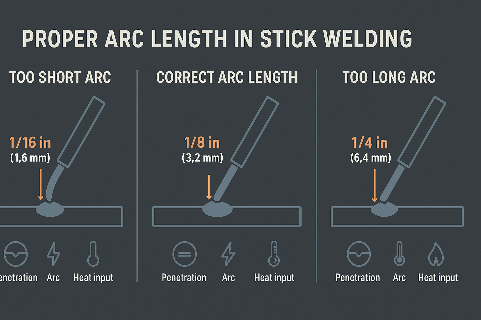
    • Sticking almost always means you’re running too cold.
    • Increase amperage by 10–15 amps and try again.
    • Why: Low current can’t sustain a stable arc. The electrode cools too quickly and bonds to the workpiece.
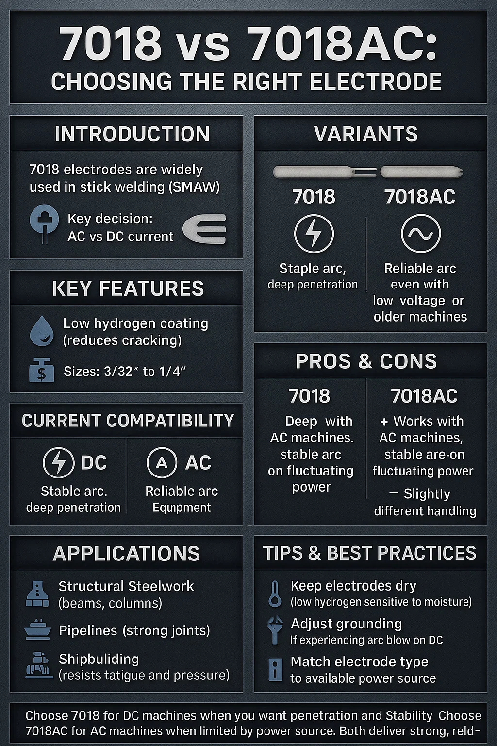
    • Rule of thumb: For 1/8″ (3.2mm) 7018 rod, use 90–110A. For 5/32″ (4mm), use 120–150A.

    Step 2: Inspect Your Ground Clamp ($0–$40)

    • Check that the ground clamp is tight on clean, bare metal.
    • If the clamp is loose, tighten it. If it’s corroded, clean it with a wire brush or replace it.
    • Why: A loose or corroded ground connection increases resistance, reducing current flow to the workpiece.
    • What to check:
      • Is the clamp jaw making full contact?
      • Is the cable connection tight at the clamp?
      • Is the workpiece surface clean where the clamp sits?

    Step 3: Dry Your Electrodes ($5–$15)

    • If your rods have been exposed to humidity, they may be damp.
    • Store them in a dry rod oven or sealed container.
    • If you don’t have an oven, use fresh rods from a sealed package.
    • Why: Moisture in the flux coating weakens the arc and makes initiation difficult.

    Step 4: Clean Your Workpiece ($0–$20)

    • Remove rust, mill scale, paint, or dirt with a wire brush, wire wheel, or grinding stone.
    • Clean a 2–3 inch area around your intended weld.
    • Why: Contamination blocks current flow and creates a weak, unstable arc.

    Step 5: Check Your Electrode Holder ($15–$50)

    • Inspect the jaw for wear, corrosion, or damage.
    • If the jaw is worn, the clamp won’t grip the electrode firmly, causing poor contact.
    • Replace if necessary.

    Fix Options (Ranked)

    1. Adjustment (FREE)

    • Increase amperage by 10–15 amps.
    • Tighten ground clamp.
    • Clean workpiece.
    • When to use: First troubleshooting step. Works 70% of the time.

    2. Consumable Change (~$10–$50)

    • Replace old or damp electrodes with fresh rods.
    • Replace corroded ground clamp.
    • When to use: If rods are old or ground clamp is visibly corroded.

    3. Part Replacement (~$15–$50)

    • Replace worn electrode holder.
    • Replace damaged ground clamp.
    • When to use: If jaw is cracked, worn, or clamp is beyond cleaning.

    Recommended Fix: Upgrade Your Electrode Holder

    A quality electrode holder ensures consistent jaw grip and reliable current flow. The YESWELDER Welding Electrode Holder is a solid upgrade that prevents many sticking issues caused by poor contact.

    Why it works:

    • Pure copper construction for superior conductivity.
    • Heavy-duty jaw with strong bite force (300A rated).
    • Insulated handle stays cool during extended use.
    • Durable design resists wear and corrosion.

    When to use it:

    • Your current holder is worn or corroded.
    • You’re upgrading from a cheap or damaged stinger.
    • You want consistent, reliable arc initiation.

    When NOT to use it:

    • Your current holder is brand new and working fine.
    • The problem is low amperage or dirty workpiece (fix those first).

    YESWELDER Welding Electrode Holder pure copper Brass Materials 300AMP, for SMAW (MMA) Stick Electrode Welding
    • PURE COPPER: Our clamp has a higher copper content than others. Therefore, better conductivity, safer and more improved cable connection.
    • MAXIMUM AMPERAGE:Up to 300A.
    • COMFORTABLE OPERATION: Great for most ARC, Stick welding jobs. Easy to operate at a newly designed level for good hand clearance and better hold.
    • SAFETY DESIGN: Heat resistant handle, made of arc-resistant insulation and impact resistant material.
    • METHOD: This 300A welding electrode holder connects to the welding cable and conducts the welding current to the electrode. The insulated handle is used to guide the electrode over the weld joint and feed the electrode over the weld joint and feed the electrode into the weld puddle as it is consumed.

    Last update on 2026-06-05 / Affiliate links / Images from Amazon Product Advertising API

    Comparable Options

    Lincoln Electric Industrial 200 Amp Electrode Holder – Premium option with copper alloy jaw and ergonomic handle. Best for professional/production work. ~$27.

    Reboot 300AMP Electrode Holder – Budget-friendly, heavy-duty. Good for occasional use. ~$15–$18.

    Common Mistakes

    • Running too cold: Beginners often fear high amperage. Low current is the #1 cause of sticking. Increase heat.
    • Ignoring ground clamp corrosion: A corroded clamp looks fine but kills conductivity. Clean or replace it.
    • Using old, damp rods: Moisture in the flux weakens the arc. Store rods in a dry oven or sealed container.
    • Not cleaning the workpiece: Rust and mill scale block current. Always brush the area before welding.
    • Striking too slowly: Strike the rod quickly and confidently. A hesitant strike can cause sticking. Move the rod away immediately after arc initiation.

    FAQ (Snippet-Optimized)

    Q: Why does my electrode stick even at high amperage? A: Check your ground clamp. A loose or corroded clamp prevents current flow, regardless of amperage. Clean and tighten it.

    Q: Can damp electrodes cause sticking? A: Yes. Moisture in the flux coating weakens arc initiation. Store rods in a dry oven or sealed container.

    Q: How do I know if my ground clamp is bad? A: Look for corrosion, loose connections, or a worn jaw. If the clamp won’t tighten or the jaw is cracked, replace it.

    Q: Is sticking dangerous? A: Yes. A stuck electrode can cause sudden arc flare-ups and spatter. Always wear proper PPE and disconnect power if you need to free a stuck rod.

    Q: What’s the best amperage for 1/8″ 7018 rod? A: 90–110A. Check your rod box for the manufacturer’s recommendation—it varies by brand and coating.

    Next Steps

    Related troubleshooting guides:

    Upgrade your setup:

    For more welding fixes and gear options, see our full resource page: https://blog.weldsupportparts.com/links/

  • Arc Control: Why Arc Length Matters in Stick Welding — Overview & Review

    Arc Control: Why Arc Length Matters in Stick Welding — Overview & Review

    Introduction

    Arc length is one of the most important variables in stick welding, and this guide—Arc Control: Why Arc Length Matters in Stick Welding—breaks down exactly why. The book explains how arc length influences penetration, bead shape, stability, and overall weld quality. For new welders trying to stop sticking and wandering arcs, and for experienced welders chasing cleaner, more consistent beads, this resource provides straightforward direction.

    Key Features

    This guide focuses entirely on understanding and maintaining proper arc length. Core topics include:

    • How arc length affects heat input and penetration
    • How arc stability changes with electrode angle and travel speed
    • The relationship between arc length, puddle control, and weld bead behavior
    • Visual diagrams that show what “too long” and “too short” arcs look like
    • Simple, actionable tips welders can use immediately

    It’s written in plain language with enough detail to be useful without overwhelming beginners.

    Pros & Cons

    Pros

    • Clear explanations of how arc length affects weld quality
    • Applicable to all experience levels
    • Helpful illustrations and diagrams
    • Strong focus on practical, real-world improvement

    Cons

    • Doesn’t include advanced technical data
    • Could go deeper for welders who already have strong arc control

    Who It’s For

    This guide fits welders who want more consistency and better quality out of their SMAW work. Ideal groups include:

    • Welding students learning fundamentals
    • DIY welders trying to reduce sticking and uneven beads
    • Working welders who want tighter control and repeatable results
    • Anyone who struggles with keeping a steady arc length

    What Makes It Unique

    Most welding books touch on arc length but don’t spend much time on it. This guide focuses specifically on that variable and explains it step-by-step. The visuals help welders understand what they should see, and the practical advice makes it easy to apply on the next weld.

    Buying Tips

    For the best learning experience:

    • Look for editions that include diagrams, photos, or companion videos
    • Choose the latest version if updates are available
    • Make sure you have basic PPE and electrodes on hand so you can practice
    • Pair the guide with a machine that has stable output—helpful when learning arc control

    Conclusion

    Arc Control: Why Arc Length Matters in Stick Welding is a solid resource for anyone wanting stronger, cleaner, and more consistent stick welds. It breaks down arc length in a way that welders can understand and apply immediately. Beginners and seasoned welders alike will find something useful here.

    This article may contain Amazon affiliate links. We may earn a small commission at no extra cost to you.

  • Welding with 7018: Should You Use AC or DC Current? When to Use 7018AC

    Welding with 7018: Should You Use AC or DC Current? When to Use 7018AC

    Introduction

    Welding with 7018 electrodes is a staple in shielded metal arc welding (SMAW), also known as stick welding. Known for creating strong, smooth welds, the 7018 is frequently used in critical applications such as structural steel work. A common question among welders is whether to use AC or DC current with this electrode, and when to opt for the 7018AC variant. Understanding these choices is crucial for welders, fabricators, and students striving for optimal performance.

    Types / Variants / Models

    The primary variants include:

    • 7018 Electrode: Typically used with direct current electrode positive (DCEP).
    • 7018AC Electrode: Specifically designed for alternating current (AC) applications.

    Each variant excels under different conditions, making the choice between them vital depending on the available equipment and project requirements.

    Key Features or Specifications

    • Coating Composition: Low hydrogen, iron powder which minimizes the risk of cracking.
    • Current Type:
      • 7018: Best with DCEP for stability and penetration.
      • 7018AC: Optimized for AC, offering good arc stability even with lower voltage machines.
    • Sizes: Available from 3/32″ to 1/4″, depending on thickness needs.
    • Certifications: Meets AWS A5.1 standards ensuring quality and reliability across structural applications.

    The differences in current compatibility directly affect arc stability and penetration, essential for achieving robust, high-quality welds.

    Usage & Compatibility

    Welding Processes:

    • SMAW (Stick Welding): The preferred method for 7018, ensuring strength in welds.

    Machine Compatibility:

    • DC Machines: Offer stable arcs with deeper penetration for the standard 7018.
    • AC Machines: Enable the use of 7018AC, overcoming limitations of older or less robust machines prone to arc interruptions.

    Pros and Cons:

    • 7018 with DC:
      • Pros: Deeper penetration, better arc stability.
      • Cons: Requires DC-compatible equipment.
    • 7018AC:
      • Pros: Usable with AC machines, improved arc stability on fluctuating AC power.
      • Cons: Slightly different handling required due to AC characteristics.

    Common Applications

    Welding with 7018 electrodes is prevalent in:

    • Structural Steelwork: Essential for beams and columns due to its strength.
    • Pipeline Welding: Ensures solid joints crucial for durability.
    • Shipbuilding: Vital in combating metal fatigue and environmental pressures.

    The 7018AC variant is particularly useful in field repairs and projects where only AC power sources are available, providing necessary flexibility and reliability.

    Tips & Best Practices

    • Setup: For AC use, ensure a stable power supply to reduce fluctuations.
    • Handling: Maintain dry storage for electrodes to prevent moisture absorption, particularly for low-hydrogen types.
    • Troubleshooting: If experiencing arc blow on DC, try adjusting the grounding position or switch to 7018AC for better control.

    Avoid common mistakes such as incorrect polarity settings and improper storage, which can compromise weld quality.

     Conclusion

    Choosing between AC and DC currents for 7018 electrodes hinges on equipment availability and project needs. The 7018AC variant provides a viable option for those restricted to AC machines without sacrificing weld quality. Welders and students should assess their equipment and project requirements to make informed decisions, ensuring efficiency and optimal results in their welding tasks.

    In summary, understanding when and why to use the 7018 or 7018AC can significantly impact the success of your welding projects, guiding you toward making the best choices for each unique scenario.

Stream with Amazon Music