Tag: Shop Maintenance
-
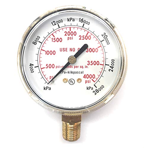
Harris 2-1/2″ x 1/4″ NPT Bottom Mount Gauge – Polished Brass Case – 1 Each (0-4000 PSI): Product Breakdown
“>
This gauge is a simple service component, but it still needs the same level of attention as any other pressure-control part on a welding setup. The listed product is a Harris 2-1/2" x 1/4" NPT bottom mount gauge with a polished brass case, marked 0-4000 PSI. That makes it a general pressure-indication gauge for gas or pressure systems where the connection, range, and physical mount match the application. Do not assume it is correct for a specific regulator or gas service without checking the actual equipment specification.
Key Takeaways
- Bottom-mount design means the pressure connection comes out of the lower side of the gauge body.
- The connection is listed as 1/4" NPT. Verify thread size, thread form, and sealing method before installation.
- Gauge range is 0-4000 PSI. That range must fit the pressure system being serviced.
- Brass case is listed. Confirm the environment and gas service before use.
- This is a replacement or service part, not a substitute for procedure review or regulator verification.
What to check before you buy
Before ordering, work through the same fit-check process you would use on any pressure instrument. Start with the connection. A 1/4" NPT gauge will not install correctly if the regulator outlet, manifold port, or adapter uses a different size or thread type. Verify whether the port is male or female, and confirm whether the installation requires thread sealant, a seal washer, or a different style of connection. NPT is a tapered pipe thread, so a loose-looking engagement is not enough to confirm compatibility.
Next, confirm range. A 0-4000 PSI gauge may be too high for some low-pressure systems because it can make readings harder to interpret at the lower end. It may also be too low for systems that can exceed the upper limit. Always check the equipment range requirement first. If the installation point sees pressure pulses or transient spikes, choose a gauge that safely exceeds the maximum expected pressure. Do not guess.
Finally, verify physical fit. The gauge is 2-1/2 inches in size, but you should still inspect the available panel space, clearance for the case, and viewing angle. If the gauge face is blocked by other fittings, a guard, cabinet, or hose bundle, it will not be useful in service.
Troubleshooting and support checks
If the gauge does not read as expected
- Check whether the gauge is actually connected to the pressure point you think it is connected to.
- Inspect the thread engagement for cross-threading, over-tightening, or adapter mismatch.
- Verify the system is under pressure and that upstream isolation valves are open.
- Check for a blocked port, plugged passage, or damaged internal movement. If the needle sticks or jitters, remove the gauge from service.
If pressure fluctuates or the reading is unstable
- Check for regulator instability, pressure surging, or a failing upstream component.
- Inspect the gauge face and case for damage that may indicate shock loading or vibration damage.
- Verify the gauge mounting location is not exposed to excessive vibration from equipment, carts, or cylinders.
If the gauge leaks after installation
- Check the thread size again. 1/4" NPT is the listed connection, but the actual mating port must match.
- Inspect the first few threads for burrs, contamination, sealant buildup, or thread damage.
- Verify the sealing method required by the host equipment. Do not assume a dry-fit, seal tape, or paste is acceptable in every service.
Product and parts notes
Based on the provided product data, the confirmed details are limited to the gauge size, mount style, thread type, brass case, and pressure range. Unknown (Verify): internal movement type, dial material, accuracy class, exact gas compatibility, backlighting, and certification details. Do not fill in those blanks from assumption. If the application depends on a specific standard, the buyer should verify the manufacturer documentation or the equipment manual before purchase.
Use this part as a direct replacement only after you compare the old gauge to the new one side by side. Match the connection, range, mounting orientation, and visible case style. If anything differs, stop and verify the application instead of forcing the part to fit.
Practical inspection steps in the shop
- Inspect the gauge lens for cracks, clouding, or impact marks before installation.
- Check the case and bezel for dents, corrosion, or deformation.
- Verify that the pointer returns smoothly to zero when the gauge is not pressurized, if that condition can be confirmed safely.
- Inspect the system connection for debris, sealant residue, or thread wear.
- Verify the gauge range is readable from the normal operating position.
If the gauge is used in a maintenance setting, include it in periodic inspection with the rest of the regulator assembly. Pressure gauges often fail gradually. A broken lens, a fogged face, or a drifting pointer is a service warning, not cosmetic damage.
Safety notes
- Depressurize the system before removing or installing any gauge.
- Use the correct tools and avoid over-torquing the connection.
- Do not use a gauge with an unreadable dial, bent pointer, or damaged case.
- Keep pressure instruments away from impact, heat, and contamination.
- Verify the service gas, system pressure, and fitting type before returning equipment to operation.
FAQ
Is this gauge for low-pressure or high-pressure service?
The listed range is 0-4000 PSI. That is the confirmed specification. Whether it is suitable for your service depends on the actual system pressure and the required operating range. Verify against the equipment manual.
Will a 1/4" NPT gauge fit any regulator?
No. It only fits equipment with a matching 1/4" NPT port and compatible sealing method. Always inspect the existing connection before ordering.
Can I use this gauge as a direct replacement if the old one looks similar?
Not without verification. Match the thread, mount style, pressure range, and panel clearance. Similar appearance does not guarantee interchangeability.
What should I do if I cannot confirm compatibility?
Stop and verify the host equipment documentation, the port size, and the service conditions. If the details remain unknown, treat the fit as Unknown (Verify) until confirmed.
Sources Checked
- ArcWeld product listing: Harris 2-1/2" x 1/4" NPT Bottom Mount Gauge – Polished Brass Case – 1 Each (0-4000 PSI)
Note: No WSP lookup page, filler metal finder page, or internal links were provided for this task, so none were used.
Related Arc Weld Part
Harris 2-1/2" x 1/4" NPT Bottom Mount Gauge – Polished Brass Case – 1 Each (0-4000 PSI)
2-1/2" bottom mounted gauge. 1/4" pipe thread. Brass body and case. 0-4000 PSI
View at Arc Weld Store

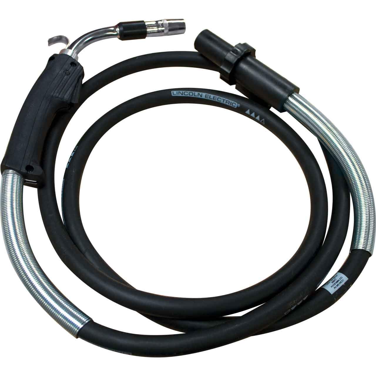
Lincoln Electric K2951-1 Magnum PRO Curve 300 MIG Welding Gun, Semi-Automatic, 10 ft Cable: Product Breakdown
“>
The Lincoln Electric K2951-1 Magnum PRO Curve 300 MIG Welding Gun is a shop-use welding gun for semi-automatic MIG applications. For buyers and maintenance teams, the main question is not just what the gun is, but whether it matches the feeder, connection style, consumables, and duty cycle expectations of the job. This breakdown focuses on practical verification steps before installation and during service.
The listed configuration includes a 10 ft cable. That length is common for controlled handling in fabrication and maintenance work, but fit and reach still need to be checked against the actual work area and feeder placement. If the gun is being ordered as a replacement or backup, verify the end connections and the wire feed setup before relying on it in production.
Key Takeaways
- Verify the gun connection style before ordering. Unknown (Verify) if your feeder uses a different interface.
- The 10 ft cable supports general shop handling, but cable routing and feeder location affect practical reach.
- Use this as a support-part decision, not a stand-alone welding procedure decision.
- Check consumables, liners, and drive-roll compatibility with the wire you actually run.
- Inspect the cable, neck, trigger, and pin interfaces before first use and after any impact or overheating event.
What to Check Before Installation
Do not assume a MIG gun fits because it is from the same brand or product family. Confirm the setup by inspection.
- Check the feeder connection: inspect the gun end and the feeder-side interface. If the connector type is not confirmed by the machine manual or parts list, mark it Unknown (Verify).
- Inspect cable condition: look for cuts, crushed sections, blistering, or stiffness that indicates heat damage or internal wear.
- Verify trigger action: the trigger should move smoothly and return consistently. Any sticking or intermittent response should be corrected before use.
- Inspect the neck and nozzle area: confirm the neck is not bent and the nozzle threads or retaining features are intact.
- Confirm wire size and liner match: the wire size you plan to run must match the liner and contact tip setup. If not confirmed, treat it as Unknown (Verify).
Practical Troubleshooting and Support
If the gun is installed but feed quality is poor, start with the simplest checks. Most complaints are related to setup, wear, or contamination rather than the gun body alone.
Wire feed is inconsistent
- Check: drive rolls, liner condition, and contact tip wear.
- Inspect: cable routing for tight bends, pinches, or loops that increase drag.
- Verify: the wire diameter and wire type match the consumable stack-up. Unknown (Verify) if documentation is not available.
Arc starts poorly or sputters at the gun
- Check: contact tip fit, nozzle cleanliness, and wire stickout.
- Inspect: for spatter buildup around the nozzle and front-end components.
- Verify: shielding gas delivery, hose integrity, and machine settings at the feeder. Do not assume the gun is the only issue.
Trigger or control response is intermittent
- Check: the gun lead and connector pins for looseness or contamination.
- Inspect: the trigger housing for damage, heat exposure, or liquid intrusion.
- Verify: continuity and machine-side input functions if the gun appears mechanically sound.
Product and Parts Considerations
This product page is for the Lincoln Electric K2951-1 Magnum PRO Curve 300 MIG Welding Gun, Semi-Automatic, 10 ft Cable. Use the product page as the starting point for the exact item, then confirm related parts in your own machine and consumable records.
Common support-part questions include the liner, contact tip series, nozzle style, diffuser, and connection hardware. Those details must be verified against the actual equipment and existing consumables. If a part number is not listed in your machine documentation or the product source, it should remain Unknown (Verify).
For product reference and ordering context, use the ArcWeld product page here: Product not found.
How to Use This Gun in a Maintenance Workflow
In maintenance environments, a MIG gun is often moved between jobs, machines, and operators. That makes inspection more important than initial purchase. Build a short pre-use routine:
- Inspect the cable jacket from feeder to gun neck.
- Check the trigger for full travel and return.
- Confirm the nozzle is clean and the tip is appropriate for the wire in use.
- Verify the feeder connection is secure.
- Run a short test bead on scrap before releasing the gun to production.
If problems appear after a move or drop, assume mechanical damage until inspection proves otherwise. Hidden damage in the lead can cause intermittent feed issues that are difficult to isolate later.
Selection Starting Point for Filler Metal
This gun is a support component. The filler metal decision still depends on base material, process settings, shielding gas, and procedure requirements. If you need a starting point for wire selection and related product references, use the WSP filler metal finder only as a selection starting point, not as a guaranteed procedure approval source.
Filler metal selection page: Unknown (Verify)
If your workflow includes a documented filler metal path, compare the wire family, diameter, and machine setup to your internal procedure sheets before welding. Do not assume a general product match is acceptable for every application.
Safety Notes
- De-energize equipment before installing, removing, or inspecting the gun.
- Do not use a damaged lead, cracked housing, or overheated front-end assembly.
- Hot nozzle and contact tip parts can burn skin immediately after welding.
- Keep cable routing clear of sharp edges, moving parts, and pinch points.
- Use the machine manual and shop procedure for final setup. This article does not replace them.
FAQ
Is the Lincoln Electric K2951-1 Magnum PRO Curve 300 MIG Welding Gun a direct replacement for every Lincoln feeder?
No. Do not assume that. Verify the connection style, control interface, and gun compatibility against the feeder documentation. If the machine side is not confirmed, mark it Unknown (Verify).
Does the 10 ft cable make it suitable for all shop layouts?
No. The 10 ft cable is a usable starting point, but actual reach depends on feeder placement, cart layout, and the route the cable must follow. Measure the work path before installation.
Can I choose consumables from a product page alone?
No. Use the product page and your machine documentation together. Confirm nozzle style, contact tip series, liner size, and wire diameter before ordering parts.
Should filler metal pages be treated as final procedure approval?
No. Treat filler metal pages as selection starting points only. Final approval still depends on your WPS, base material, shielding gas, and procedure requirements.
Sources Checked
- ArcWeld product page: Lincoln Electric K2951-1 Magnum PRO Curve 300 MIG Welding Gun, Semi-Automatic, 10 ft Cable
- Provided internal product reference in the task prompt
For buyers, the value of this gun is not a list of marketing features. It is whether the unit fits the feeder, supports the wire you actually run, and holds up to the handling pattern in your shop. Verify the interface, inspect the cable, and confirm the consumable stack before putting it into service.
Related Arc Weld Part
Lincoln Electric K2951-1 Magnum PRO Curve 300 MIG Welding Gun, Semi-Automatic, 10 ft Cable
Lincoln Electric K2951-1 Magnum PRO Curve 300 MIG welding gun is built for semi-automatic MIG welding applications and includes a 10 ft cable for controlled handling and day-to-day shop use; the Curve 300 design is intended to support consistent feeding and operator comfort for fabrication and maintenance work—please confirm your welder/feeder and gun connection style match the Magnum PRO Curve 300 configuration b…
View at Arc Weld Store