Tag: Inspection

  • Rego 912JS20 20″ Pigtail Hose, 1/4″ Tube, 1/4″ MNPT x MPOL, Short Nipple, 7/8″ Hex: Product Breakdown

    Rego 912JS20 20″ Pigtail Hose, 1/4″ Tube, 1/4″ MNPT x MPOL, Short Nipple, 7/8″ Hex: Product Breakdown

    Product not found.
    “>Rego 912JS20 20" Pigtail Hose, 1/4" Tube, 1/4" MNPT x MPOL, Short Nipple, 7/8" Hex

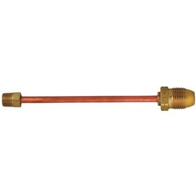
    The Rego 912JS20 is a compact pigtail assembly used in LP gas service connections. The product title identifies the key geometry: 20-inch length, 1/4-inch tube, 1/4-inch male NPT on one end, male POL on the other, and a short nipple with a 7/8-inch hex for wrench access. For buyers and maintenance teams, the main question is not only whether the part fits the connection, but whether it fits the service condition, regulator arrangement, and inspection standard used on site.

    This is a practical breakdown for selection and field use. It does not replace the equipment manual, local code requirements, or the gas system owner’s procedure. If any connection detail is unclear, use Unknown (Verify) and confirm before installation.

    Key Takeaways

    • The Rego 912JS20 is a pigtail assembly for LP gas service connections.
    • It is identified as a 20-inch assembly with 1/4-inch tube construction.
    • One end is 1/4-inch MNPT; the other end is MPOL.
    • The short nipple and 7/8-inch hex suggest easier wrench access in tight spaces.
    • Final suitability depends on gas type, regulator interface, seal method, and system requirements. Unknown (Verify).

    What the part is for

    A pigtail hose links a cylinder or supply point to downstream gas equipment. In LP gas service, the part must match the connection style at both ends and must be suitable for the gas service conditions. The Rego 912JS20 is presented as a compact connection component for regulator and cylinder connection applications.

    Use this kind of assembly when the system needs a short, serviceable connector rather than a rigid direct connection. The short nipple and hex feature are relevant where wrench clearance is limited. That does not remove the need for proper tightening access, leak testing, and visual inspection after installation.

    Fit-up checks before purchase

    Before ordering, verify the following points against the equipment already in service:

    • Connection type at the inlet: Confirm the system uses 1/4-inch MNPT. Do not assume thread form from appearance alone.
    • Connection type at the outlet: Confirm the mating side is MPOL. If the cylinder or regulator uses a different interface, this part will not be correct.
    • Length requirement: Confirm 20 inches is enough for routing without strain, kinking, or side loading.
    • Space for tightening: Check whether the 7/8-inch hex gives adequate wrench access in the installed position.
    • Service condition: Verify the hose routing will avoid sharp edges, heat exposure, and contact with moving parts.

    If any of those points are uncertain, mark the requirement as Unknown (Verify) and compare against the current assembly or the equipment manual.

    Installation and inspection steps

    Use a consistent field process. Do not rely on visual similarity alone.

    1. Inspect the packaging and part marking. Confirm the received part matches the purchase description and the intended connection style.
    2. Check both ends before installation. Verify the 1/4-inch MNPT end and the MPOL end are clean, undamaged, and free of galling or debris.
    3. Inspect the hose body. Look for cuts, abrasion, twists, flattening, swelling, or any sign of damage from shipping or storage.
    4. Verify routing. Place the hose so it is not stretched tight, not sharply bent, and not rubbing against adjacent hardware.
    5. Tighten with proper access. Use the short nipple hex only as intended for service access. Do not force tools if the fit-up is poor.
    6. Leak-test after installation. Follow the site’s approved leak-test method immediately after assembly and again after the system is pressurized.
    7. Recheck after use. Inspect for looseness, wear, heat discoloration, or abrasion during regular service intervals.

    Troubleshooting support

    If a connection does not assemble cleanly, stop and verify the mismatch before applying more torque.

    Problem: Threads do not start by hand

    • Check thread type and size. Unknown (Verify) if the mating component is not clearly identified.
    • Inspect for cross-threading, debris, or damaged threads.
    • Do not use tools to force the first engagement.

    Problem: Assembly will not seal after tightening

    • Verify the mating side is the correct connection style for the service.
    • Inspect sealing surfaces and confirm the correct seal method is being used for the system.
    • Leak-test with the approved method. Do not depend on smell, sound, or visual judgment alone.

    Problem: Hose routing is too tight

    • Verify the 20-inch length is appropriate for the installation layout.
    • Check for unnecessary bends or forced alignment at the regulator or cylinder end.
    • Replace with a correctly sized assembly if the line is under tension.

    Product and parts notes

    Product: Rego 912JS20 20″ Pigtail Hose, 1/4″ Tube, 1/4″ MNPT x MPOL, Short Nipple, 7/8″ Hex

    Use case: LP gas regulator and cylinder connection applications, subject to system verification.

    Key selection points: connection style, hose length, wrench access, and service routing.

    Uncertain technical details: gas compatibility, pressure rating, specific materials, and certification status are Unknown (Verify) from the provided source data.

    Safety notes

    • Do not install any gas connection component without confirming the correct connection type and service application.
    • Leak-test every connection after installation and after any maintenance work on the gas train.
    • Keep the hose away from heat, abrasion points, and moving equipment.
    • Replace any hose that shows cracking, damage, corrosion at the ends, or deformation.
    • Follow site procedures and local requirements for LP gas work. Unknown (Verify) where the governing standard is not specified.

    FAQ

    Is the Rego 912JS20 a direct replacement for every LP gas pigtail?

    No. It is only suitable where the connection type, hose length, and service arrangement match the equipment. Verify all fit-up details before use.

    Can the short nipple and 7/8-inch hex be used to solve a poor layout?

    They may help with wrench access, but they do not correct a bad routing plan. If the hose is forced into position, change the layout or select a different assembly.

    What should be checked after installation?

    Verify thread engagement, final wrench access, hose routing, and leak integrity. Reinspect after the system is placed back in service.

    Is the gas compatibility confirmed in the source data?

    No. Gas compatibility is not fully specified in the provided source details and should be treated as Unknown (Verify).

    Sources Checked

    • ArcWeld product page: Rego 912JS20 20″ Pigtail Hose, 1/4″ Tube, 1/4″ MNPT x MPOL, Short Nipple, 7/8″ Hex
    • Provided source description for the Rego 912JS20 assembly

    Related Arc Weld Part

    Rego 912JS20 20" Pigtail Hose, 1/4" Tube, 1/4" MNPT x MPOL, Short Nipple, 7/8" Hex

    Rego 912JS20 20" Pigtail Hose, 1/4" Tube, 1/4" MNPT x MPOL, Short Nipple, 7/8" Hex

    Rego 912JS20 pigtail assembly with a 20" length and 1/4" tube, designed to connect LP gas service using a 1/4" male NPT inlet and a male POL outlet. Includes a short nipple with a 7/8" hex for secure wrench tightening and serviceability in tight spaces. Intended for regulator and cylinder connection applications where a compact, durable pigtail is required. Verify gas compatibility, leak-test all connections after…

    View at Arc Weld Store
  • Kohler Nut Wing #KOH-12 100 01-S: Replacement Part Breakdown

    The Kohler Nut Wing #KOH-12 100 01-S is a replacement part reference that maintenance buyers and shop support teams may encounter when servicing equipment with Kohler components. For a wing nut, the important question is not just the part name. It is whether the thread, material condition, clamping face, and fit match the application you are repairing. If any of those points are uncertain, verify before installation.

    This draft keeps the focus on practical identification and support steps. It does not assume compatibility beyond the part reference provided. For equipment-specific use, confirm the machine model, thread match, and assembly requirements against the OEM documentation or an authorized parts source.

    Key Takeaways

    • Use the exact part reference when ordering or cross-checking: Kohler Nut Wing #KOH-12 100 01-S.
    • Do not assume fit from the part name alone. Verify thread, diameter, pitch, and seating style.
    • Inspect the mating stud or bolt before replacing the wing nut. A damaged stud will cause repeat failure.
    • If the application is on a machine or service panel, check for vibration, heat, corrosion, and hand-tightening requirements.
    • When details are unknown, mark them as Unknown (Verify) rather than guessing.

    What This Part Reference Tells You

    A wing nut is typically used where hand removal or frequent access is needed. The Kohler part reference suggests an OEM-style replacement component, but the reference alone does not confirm the thread size, finish, or material. Those details matter in field service because a wing nut that starts on the thread but does not seat correctly can loosen, gall the stud, or fail under vibration.

    If you are tracking down the correct replacement, document the following before you order:

    • Equipment model and serial number
    • Location of the fastener on the machine
    • Visible thread size and pitch, if measurable
    • Old part condition: intact, stripped, cracked, corroded, or heat damaged
    • Any washer, lock element, or spacer used with the nut

    Troubleshooting and Support Checks

    Use a simple inspect-verify routine before installing a replacement wing nut.

    Check

    • Check the removed nut for thread wear, flattening, cracks, and corrosion.
    • Check the stud or bolt for damaged crests, mushrooming, or cross-thread marks.
    • Check the mating surface for burrs, distortion, or debris that can prevent full seating.
    • Check whether the application is hand-tightened only or exposed to repeated vibration.

    Inspect

    • Inspect the thread start on the replacement part. The first few turns should not show deformation.
    • Inspect for any contamination such as paint, rust, or metal chips in the female or male thread.
    • Inspect nearby hardware for signs of looseness that could indicate a larger fastener issue.

    Verify

    • Verify thread match by measuring or test-fitting by hand. Do not force engagement.
    • Verify clearance around the wing tips so the nut can be turned without interference.
    • Verify the retained assembly still closes, clamps, or secures correctly after tightening.
    • Verify that any replacement maintains the same service access and does not interfere with covers or guards.

    If the wing nut begins to bind immediately, stop and recheck the thread. Cross-threading can damage both the nut and the stud. If the part spins freely but never tightens, the thread pitch or diameter may not match, or the stud may already be worn beyond serviceable condition.

    Replacement Part Breakdown

    For service planning, break the replacement decision into four parts:

    1. Identification: Confirm the exact part reference on the existing machine record or removed hardware.
    2. Fit: Confirm thread size, thread pitch, and required seating style. Unknown (Verify) if not documented.
    3. Condition of mating hardware: Replace or repair the stud, bolt, washer, or panel hardware if damaged.
    4. Application demands: Consider vibration, temperature, contamination, and frequency of removal.

    This is the point where many repair jobs go wrong. A wing nut is often treated as a generic item, but in maintenance work the wrong fastener can create repeat service calls. The cost of verifying fit is lower than repairing a stripped stud or a loose cover.

    Product / Parts Section

    The provided product reference is:

    • Product name: Kohler Nut Wing #KOH-12 100 01-S
    • ASIN: B00CSBT27G
    • Amazon affiliate shortcode:

      No products found.

    No compatibility, dimensions, material grade, or certification details are confirmed in the source data provided here. Treat those details as Unknown (Verify) until checked against the OEM parts documentation or the product listing from the approved source.

    Safety Notes

    • Lock out and tag out equipment before removing guards, covers, or retained assemblies when required by site procedure.
    • Do not substitute a wing nut in a load-bearing or critical retention point unless the application specifically allows it.
    • Do not force mismatched threads. Forced installation can damage the fastener and nearby components.
    • If corrosion is present, use appropriate eye protection and hand protection when cleaning or removing hardware.

    FAQ

    Is the Kohler Nut Wing #KOH-12 100 01-S a universal replacement?

    No. The part reference alone does not prove universal fit. Verify the thread, size, and application before use.

    What should I do if the new wing nut will not start by hand?

    Stop and inspect the stud or bolt for damage, contamination, or incorrect thread pitch. If needed, confirm the replacement against the OEM parts record. Do not force it.

    Can I reuse the old stud if the wing nut was stripped?

    Only if inspection shows the stud is still in serviceable condition. If the threads are flattened, galled, or deformed, replace the stud or related hardware as required.

    What details are still unknown?

    Material, finish, exact dimensions, and application-specific compatibility are Unknown (Verify) based on the provided source data.

    Sources Checked

    • Provided Amazon product reference for Kohler Nut Wing #KOH-12 100 01-S
    • Provided ASIN registry reference: B00CSBT27G

    Use this part only after fit and application checks are complete. For maintenance purchasing, the safest path is to confirm the mating hardware and the equipment model before release to the field.

    Disclosure: As an Amazon Associate, Weld Support Parts may earn from qualifying purchases.

  • CK 3P8GS Glass Cup Size 8, 1/2″ x 1-7/8″, 10 pack: Product Breakdown

    CK 3P8GS Glass Cup Size 8, 1/2″ x 1-7/8″, 10 pack: Product Breakdown

    Product not found.
    “>CK 3P8GS Glass Cup Size 8, 1/2" x 1-7/8", 10 pack

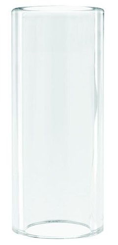
    The CK 3P8GS Glass Cup Size 8, 1/2" x 1-7/8", 10 pack is a TIG torch support part for situations where visibility matters. The product description identifies it as a high-temperature glass cup used for work in inside corners, inside pipe, and around tubing. That makes it relevant to fabricators and maintenance crews who need better line-of-sight to the arc and puddle while working in tight geometry.

    This article is a practical breakdown for buyers and support teams. It focuses on what this part is for, what to verify before ordering or installing, and how to troubleshoot common fit and performance issues. Use the product details as a starting point, then confirm torch compatibility and size requirements before putting the cups into service.

    Key takeaways

    • Glass cups are selected when visibility around the weld zone is a priority.
    • This listing is for a package of 10 cups.
    • Size and torch compatibility must be verified before use.
    • Glass consumables need inspection for chips, cracks, and heat damage before each job.
    • If fit or gas coverage is uncertain, treat the setup as Unknown (Verify) until the torch and accessory stack-up are confirmed.

    What the product is used for

    High-temperature glass cups are used to help improve visibility in restricted TIG welding positions. In practice, that means they are useful when the operator needs to watch the tungsten, filler addition, and puddle movement more clearly than with an opaque cup. The product description specifically points to inside corners, inside pipe, and work around tubing.

    That use case is important for welders and supervisors because visibility can affect torch angle, access, and consistency. A clearer view can help the operator maintain control in confined areas, but the cup still has to match the torch and the job setup. Do not assume a glass cup is suitable for every torch body, collet body, or gas lens arrangement. Verify the full stack-up before installation.

    Check before you order

    Before purchasing, confirm the torch family, cup size requirement, and any related accessory dimensions. The listing identifies the part as Size 8 with overall dimensions of 1/2" x 1-7/8", but the exact torch compatibility is not stated in the product data provided here. If your maintenance records or job traveler do not already identify the correct setup, mark it Unknown (Verify) and match it to the torch hardware in hand.

    • Check the torch model and accessory thread or interface requirements.
    • Inspect the existing cup and holder for size markings, wear, and damage.
    • Verify that the work area actually benefits from improved visibility before changing consumables.
    • Confirm the pack quantity of 10 is appropriate for your usage rate and spares policy.

    Install and setup support

    Install the cup only after the torch has been made safe and cooled. Remove the current cup and compare the physical dimensions, seating surface, and fit behavior against the new glass cup. Because no compatibility chart is provided in the source data, the exact mating parts remain Unknown (Verify). Do not force a cup into a holder or assume a loose fit is acceptable.

    When setting up for first use, use a short verification pass:

    • Check that the cup seats evenly without rocking.
    • Inspect the gas coverage at a low-risk test weld or dry run position.
    • Verify the torch can still reach the joint without overextending the operator’s wrist or changing technique beyond normal practice.

    Troubleshooting and support

    If the part does not perform as expected, work through the issue in order. Start with fit, then condition, then gas flow and technique. Do not jump straight to process changes until the hardware is confirmed.

    Problem: the cup does not fit correctly

    • Check the torch cup interface and compare it to the removed part.
    • Inspect for burrs, deformation, or contamination on the holder.
    • Verify the size designation is correct for the torch assembly. If not confirmed, treat it as Unknown (Verify).

    Problem: visibility improved, but gas coverage seems inconsistent

    • Check the gas supply, torch assembly, and any other accessories already in use.
    • Inspect for leaks, loose connections, or damaged sealing surfaces.
    • Verify that the issue is not related to technique, stickout, or work position before replacing additional parts.

    Problem: the cup shows damage after use

    • Check for impact marks from handling or contact with the workpiece.
    • Inspect for cracks, chips, or heat stress before reuse.
    • Verify the operator is giving the cup enough clearance in tight corners and pipe work.

    Product and parts notes

    The available product data identifies this as the CK 3P8GS Glass Cup Size 8, 1/2" x 1-7/8", 10 pack. It is presented as a glass high-temperature cup for TIG use in visibility-limited applications. No additional specs, material certifications, or compatibility claims are provided in the source data, so those details remain Unknown (Verify).

    For buyers, the main value point is practical access in constrained weld positions. For maintenance teams, the pack of 10 may help reduce small-part shortages at the bench or in the field, but order quantity should still match the shop’s usage and consumable control process.

    Safety notes

    • Handle glass consumables carefully. Chips and cracks can worsen during use.
    • Let the torch cool before changing cups or inspecting the holder.
    • Do not use damaged cups in production welding.
    • Verify the torch is isolated and the work area is safe before maintenance.
    • Use normal TIG PPE and follow site welding safety procedures.

    FAQ

    What is the CK 3P8GS glass cup used for?

    It is used in TIG applications where visibility is important, especially inside corners, inside pipe, and around tubing.

    Does this product listing confirm torch compatibility?

    No. The provided product data does not include a compatibility chart. Torch fit remains Unknown (Verify) until matched to the actual torch hardware.

    How should I inspect the cup before use?

    Check for chips, cracks, or deformation. Inspect the seating area and verify the cup installs evenly and securely before welding.

    Why choose a glass cup instead of a standard opaque cup?

    The main reason is visibility. A glass cup can help the operator see the weld zone better in tight or obstructed positions, but it still has to be properly matched to the torch setup.

    Sources checked

    • ArcWeld product page: CK 3P8GS Glass Cup Size 8, 1/2" x 1-7/8", 10 pack

    Related Arc Weld Part

    CK 3P8GS Glass Cup Size 8, 1/2" x 1-7/8", 10 pack

    CK 3P8GS Glass Cup Size 8, 1/2" x 1-7/8", 10 pack

    Glass high temperature glass cups are used in applications where visibility is an issue such as inside corners, inside pipe, around tubing, etc. Package of 10

    View at Arc Weld Store
  • Markal 96270, Silver Steak Markal PRO Holder, Pack of (1): Replacement Part Breakdown

    The Markal 96270, Silver Steak Markal PRO Holder, Pack of (1) is best treated as a consumable support item in a marking system, not as a standalone process-critical welding component. For maintenance buyers, shop leads, and support teams, the main question is simple: when a holder starts to fail, what should you inspect before you replace it, and what should you verify after it arrives?

    This guide breaks the part down from a service and support angle. It does not assume undocumented compatibility, dimensions, or internal construction details. Where technical details are not confirmed here, they are listed as Unknown (Verify).

    Key Takeaways

    • The Markal 96270 listing identifies a replacement holder item, but exact internal build details are Unknown (Verify).
    • Before ordering a replacement, inspect the current holder for wear, binding, cracked body parts, or poor lead/marking retention.
    • After receipt, verify fit, actuation, retention, and general condition before putting it into service.
    • Do not assume compatibility with other Markal holders or marking formats unless confirmed by the seller or your internal part records.
    • Use the Amazon product listing only as a product reference point; do not rely on it for undocumented repair guidance.

    What This Part Is Used For

    The product name indicates a Markal PRO holder associated with Silver Steak marking use. In practice, holders in this category are used to secure and present a marking stick or similar consumable in a controlled way. The exact operating method for this specific unit is Unknown (Verify), so support teams should confirm the current tool design before attempting repair, disassembly, or substitution.

    If the holder is being used in a fabrication or maintenance environment, common failure symptoms include poor retention, inconsistent feed, damaged locking features, or a body that no longer holds alignment. Those symptoms do not prove the holder is the only problem. The marking stick, operator handling, storage conditions, or contamination can also be involved.

    Inspection Checklist Before Replacement

    Use this sequence before writing off the holder:

    1. Inspect the body. Look for cracks, bent sections, gouges, or heat damage.
    2. Check retention surfaces. Verify the part still grips the marking material consistently.
    3. Check movement. If the holder has a sliding or advancing function, verify it moves without sticking.
    4. Inspect for debris. Clean out dust, metal fines, and marker residue.
    5. Verify operator handling. Check whether the tool is being dropped, over-tightened, or stored in a way that causes premature wear.

    If any of these checks fail, document the condition with photos and note whether the problem is intermittent or continuous. That record helps avoid repeating the same failure after replacement.

    Troubleshooting Support Steps

    1) Holder will not retain the marking stick

    Check: Confirm the stick type matches the holder’s intended size and format. Exact fit data is Unknown (Verify).

    Inspect: Look for worn jaws, damaged guides, or missing internal parts.

    Verify: Test with a known good marking stick from the same inventory lot if available.

    2) Advancement feels stiff or inconsistent

    Check: Make sure the unit is not loaded with broken fragments or compacted dust.

    Inspect: Examine sliding interfaces for contamination, bending, or corrosion.

    Verify: Clean the holder and repeat the movement test before replacing the unit.

    3) Marking quality has declined

    Check: Confirm the issue is not in the marking material itself.

    Inspect: Review the tip presentation and whether the holder is keeping the stick aligned.

    Verify: Compare output against a known good holder under the same operator and surface conditions.

    Product and Parts Notes

    The only confirmed product detail provided here is the Amazon ASIN reference for the Markal 96270, Silver Steak Markal PRO Holder, Pack of (1): B074WGYF21. No additional specifications, dimensions, or repair kits are verified in the source data available for this draft.

    If you are building a replacement-part record, capture the following internally:

    • Original part name and ASIN reference
    • Observed failure mode
    • Date removed from service
    • Any matching model or lot data from packaging
    • Operator notes on fit, feel, and performance

    Do not assume a “similar” holder will work as a direct substitute unless the vendor or your own verified records confirm it.

    Support and Ordering Considerations

    For buyers, the main risk is ordering on description alone. The product title suggests a specific Markal PRO holder variant, but the available source data does not confirm cross-compatibility with other holder bodies, refill formats, or accessories. Keep that uncertainty in the purchase record and verify against your own approved-use list before standardizing the part.

    If the existing holder is failing repeatedly, review the root cause before replacement. Storage, contamination, impact damage, and incorrect loading are common contributors in marking tool service problems. A replacement part will not fix a handling issue.

    Safety Notes

    • Wear appropriate hand protection when inspecting used marking tools with sharp or worn edges.
    • Do not force a jammed mechanism apart unless the tool design and service method are confirmed.
    • Keep solvents, compressed air, and cleaning methods compatible with your site procedures.
    • Remove the holder from service if cracks, breakage, or loose internal parts are found.
    • Use lockout, housekeeping, and tool-control practices where required by site policy.

    FAQ

    Is this a complete tool or a replacement support part?

    The product name indicates a holder product. Exact internal configuration is Unknown (Verify), so confirm whether your application treats it as a complete tool, a replacement component, or a consumable support item.

    Can I use it with other Markal products?

    Not enough verified data is available here to confirm compatibility. Treat compatibility as Unknown (Verify) unless your internal part records or the seller confirm it.

    What should I check before buying a replacement?

    Inspect the existing holder for wear, binding, damage, and contamination. Verify the marking material type, the loading method, and any model identifiers from the old unit before placing an order.

    What if the new holder still does not work properly?

    Verify the marking stick or consumable, the loading method, and the operator technique. If the failure repeats, document the issue and compare the new part against the removed part for fit and function.

    Sources Checked

    • Amazon product reference provided in the task: Markal 96270, Silver Steak Markal PRO Holder, Pack of (1), ASIN B074WGYF21
    • No WSP lookup page provided
    • No filler metal finder page provided
    • No internal links provided

    Note: This draft intentionally avoids unverified specifications, pricing, certifications, and compatibility claims. Use internal records or supplier confirmation to complete any unresolved technical details.

    Matched Replacement Option

    No products found.

    Disclosure: As an Amazon Associate, Weld Support Parts may earn from qualifying purchases.

  • Listen with Audible