Tag: gas equipment
-
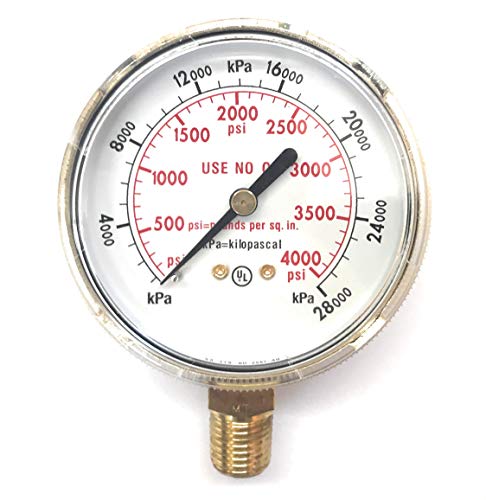
Harris 2-1/2″ x 1/4″ NPT Bottom Mount Gauge – Polished Brass Case – 1 Each (0-4000 PSI): Product Breakdown
“>
This gauge is a simple service component, but it still needs the same level of attention as any other pressure-control part on a welding setup. The listed product is a Harris 2-1/2" x 1/4" NPT bottom mount gauge with a polished brass case, marked 0-4000 PSI. That makes it a general pressure-indication gauge for gas or pressure systems where the connection, range, and physical mount match the application. Do not assume it is correct for a specific regulator or gas service without checking the actual equipment specification.
Key Takeaways
- Bottom-mount design means the pressure connection comes out of the lower side of the gauge body.
- The connection is listed as 1/4" NPT. Verify thread size, thread form, and sealing method before installation.
- Gauge range is 0-4000 PSI. That range must fit the pressure system being serviced.
- Brass case is listed. Confirm the environment and gas service before use.
- This is a replacement or service part, not a substitute for procedure review or regulator verification.
What to check before you buy
Before ordering, work through the same fit-check process you would use on any pressure instrument. Start with the connection. A 1/4" NPT gauge will not install correctly if the regulator outlet, manifold port, or adapter uses a different size or thread type. Verify whether the port is male or female, and confirm whether the installation requires thread sealant, a seal washer, or a different style of connection. NPT is a tapered pipe thread, so a loose-looking engagement is not enough to confirm compatibility.
Next, confirm range. A 0-4000 PSI gauge may be too high for some low-pressure systems because it can make readings harder to interpret at the lower end. It may also be too low for systems that can exceed the upper limit. Always check the equipment range requirement first. If the installation point sees pressure pulses or transient spikes, choose a gauge that safely exceeds the maximum expected pressure. Do not guess.
Finally, verify physical fit. The gauge is 2-1/2 inches in size, but you should still inspect the available panel space, clearance for the case, and viewing angle. If the gauge face is blocked by other fittings, a guard, cabinet, or hose bundle, it will not be useful in service.
Troubleshooting and support checks
If the gauge does not read as expected
- Check whether the gauge is actually connected to the pressure point you think it is connected to.
- Inspect the thread engagement for cross-threading, over-tightening, or adapter mismatch.
- Verify the system is under pressure and that upstream isolation valves are open.
- Check for a blocked port, plugged passage, or damaged internal movement. If the needle sticks or jitters, remove the gauge from service.
If pressure fluctuates or the reading is unstable
- Check for regulator instability, pressure surging, or a failing upstream component.
- Inspect the gauge face and case for damage that may indicate shock loading or vibration damage.
- Verify the gauge mounting location is not exposed to excessive vibration from equipment, carts, or cylinders.
If the gauge leaks after installation
- Check the thread size again. 1/4" NPT is the listed connection, but the actual mating port must match.
- Inspect the first few threads for burrs, contamination, sealant buildup, or thread damage.
- Verify the sealing method required by the host equipment. Do not assume a dry-fit, seal tape, or paste is acceptable in every service.
Product and parts notes
Based on the provided product data, the confirmed details are limited to the gauge size, mount style, thread type, brass case, and pressure range. Unknown (Verify): internal movement type, dial material, accuracy class, exact gas compatibility, backlighting, and certification details. Do not fill in those blanks from assumption. If the application depends on a specific standard, the buyer should verify the manufacturer documentation or the equipment manual before purchase.
Use this part as a direct replacement only after you compare the old gauge to the new one side by side. Match the connection, range, mounting orientation, and visible case style. If anything differs, stop and verify the application instead of forcing the part to fit.
Practical inspection steps in the shop
- Inspect the gauge lens for cracks, clouding, or impact marks before installation.
- Check the case and bezel for dents, corrosion, or deformation.
- Verify that the pointer returns smoothly to zero when the gauge is not pressurized, if that condition can be confirmed safely.
- Inspect the system connection for debris, sealant residue, or thread wear.
- Verify the gauge range is readable from the normal operating position.
If the gauge is used in a maintenance setting, include it in periodic inspection with the rest of the regulator assembly. Pressure gauges often fail gradually. A broken lens, a fogged face, or a drifting pointer is a service warning, not cosmetic damage.
Safety notes
- Depressurize the system before removing or installing any gauge.
- Use the correct tools and avoid over-torquing the connection.
- Do not use a gauge with an unreadable dial, bent pointer, or damaged case.
- Keep pressure instruments away from impact, heat, and contamination.
- Verify the service gas, system pressure, and fitting type before returning equipment to operation.
FAQ
Is this gauge for low-pressure or high-pressure service?
The listed range is 0-4000 PSI. That is the confirmed specification. Whether it is suitable for your service depends on the actual system pressure and the required operating range. Verify against the equipment manual.
Will a 1/4" NPT gauge fit any regulator?
No. It only fits equipment with a matching 1/4" NPT port and compatible sealing method. Always inspect the existing connection before ordering.
Can I use this gauge as a direct replacement if the old one looks similar?
Not without verification. Match the thread, mount style, pressure range, and panel clearance. Similar appearance does not guarantee interchangeability.
What should I do if I cannot confirm compatibility?
Stop and verify the host equipment documentation, the port size, and the service conditions. If the details remain unknown, treat the fit as Unknown (Verify) until confirmed.
Sources Checked
- ArcWeld product listing: Harris 2-1/2" x 1/4" NPT Bottom Mount Gauge – Polished Brass Case – 1 Each (0-4000 PSI)
Note: No WSP lookup page, filler metal finder page, or internal links were provided for this task, so none were used.
Related Arc Weld Part
Harris 2-1/2" x 1/4" NPT Bottom Mount Gauge – Polished Brass Case – 1 Each (0-4000 PSI)
2-1/2" bottom mounted gauge. 1/4" pipe thread. Brass body and case. 0-4000 PSI
View at Arc Weld Store
Oxy-Acetylene Torch Backfire vs Flashback: Causes and Fixes
Backfire and flashback events in oxy-acetylene torches indicate improper gas flow, tip condition issues, or unsafe operating practices. While a backfire is typically a momentary pop, a flashback is more serious and can travel into the torch or hoses, creating a significant safety hazard.
Key Takeaways
- Backfire is a short pop; flashback is a sustained flame reversal
- Dirty or damaged tips are a common cause
- Incorrect gas pressures disrupt flame stability
- Blocked hoses or regulators increase flashback risk
- Flashback arrestors are critical safety components
Problem / Context
Oxy-fuel systems rely on controlled gas flow and proper mixing at the torch tip. When this balance is disrupted, combustion can occur inside the tip or travel backward into the system. Understanding the difference between backfire and flashback is essential for safe troubleshooting and prevention.
Root Causes
- Clogged or dirty tip: restricts gas flow and causes unstable combustion
- Incorrect gas pressure: improper oxygen-to-fuel ratio
- Loose tip or connections: creates internal leaks
- Overheating tip: increases risk of ignition inside the tip
- Blocked hoses or regulators: restricts flow and pressure stability
- Missing flashback arrestors: no protection against reverse flame travel
Solution / Explanation
- Clean torch tips using proper tip cleaners sized for the orifice
- Verify gas pressures match manufacturer recommendations
- Tighten all connections securely before operation
- Allow the torch to cool if overheating occurs
- Inspect hoses and regulators for restrictions or damage
- Install and maintain flashback arrestors on both oxygen and fuel lines
Specs / Verification Notes
- Operating Pressure (Oxygen): Unknown (Verify)
- Operating Pressure (Acetylene): Unknown (Verify)
- Tip Size: Application dependent
- Flashback Arrestor Rating: Unknown (Verify)
- Hose Type: Grade R or T (application dependent)
Comparison Table
| Condition | Symptom | Severity | Correction |
|---|---|---|---|
| Backfire | Loud pop, flame extinguishes | Low | Clean tip, adjust pressure |
| Flashback | Hissing or whistling, flame inside torch | High | Clean or replace the tip |
| Clogged Tip | Unstable flame | Medium | Hissing or whistling, flame inside the torch |
| Low Gas Pressure | Weak or sputtering flame | Medium | Adjust regulator settings |
Safety Notes
Follow ANSI Z49.1 and CGA safety guidelines for oxy-fuel systems. Always use flashback arrestors and check valves. Shut off the gas supply immediately if a flashback is suspected. Never operate damaged equipment.
FAQ
What is the difference between backfire and flashback?
Backfire is a brief pop with flame extinguishing, while flashback involves flame traveling back into the torch or hoses.
What should be done during a flashback?
Immediately shut off oxygen first, then fuel gas, and inspect the system before reuse.
Can dirty tips cause flashback?
Yes. Restricted gas flow from clogged tips is a common trigger for both backfire and flashback.
Next Step
Inspect the torch system, clean the tip, and verify gas pressures before next use. Install flashback arrestors if not already present to reduce risk.
Sources Checked
- ANSI Z49.1 Safety in Welding and Cutting
- CGA (Compressed Gas Association) safety guidelines
- Oxy-fuel torch manufacturer manuals (general reference)