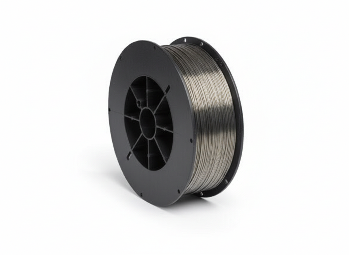
Tag: flux-cored wire

  • Why Flux-Cored Wire Is Producing Worm Tracks (And How to Stop It)

    Worm tracks in flux-cored welding are narrow, winding surface marks that usually show up on or beside the weld bead after the slag is removed. They are not normal bead texture. In most shop cases, worm tracks mean gas is being trapped or released through the slag system instead of escaping cleanly before the weld solidifies. The usual causes are moisture in the wire or joint, incorrect shielding gas, poor gas coverage, excessive voltage, excessive stickout, travel speed that outruns the slag, wrong polarity, or a flux-cored wire being run outside its intended procedure.

    The repair issue is simple: do not grind the surface smooth and call it fixed. If worm tracks are visible, first determine whether they are only superficial slag marks or connected to porosity below the surface. For production, structural, pressure, code, or customer-inspected work, follow the WPS and inspection requirements. Compatibility also matters. Verify the wire classification, wire diameter, polarity, shielding gas, contact tip size, liner, drive roll type, gas nozzle condition, and manufacturer range before changing parts or settings. Gas-shielded flux-cored wires commonly require 100% CO2 or an argon/CO2 mix depending on the wire; self-shielded wires do not use external gas. Mixing those setups is a fast path to defects.

    Related setup checks: MIG wire burnback troubleshooting, MIG wire birdnesting causes, and MIG gun whip cable drag problems.

    Common Symptoms

    • Thin worm-like lines on the bead after slag removal.
    • Small surface channels running with the weld direction.
    • Pinholes or porosity near the same area as the tracks.
    • Excess spatter, rough slag release, or glassy slag islands.
    • Good-looking arc sound but poor bead surface after chipping.
    • Defect appears worse after opening a damp spool or welding over rusty plate.

    Likely Causes

    CauseWhat It DoesFirst Check
    Moisture in wire or jointCreates gas that escapes through the slagTry dry wire on clean scrap
    Wrong shielding gasChanges arc, slag, and weld chemistryVerify gas against wire data sheet
    Low or turbulent gas coverageAllows atmosphere into the arc zoneInspect nozzle, diffuser, hose, regulator, and drafts
    Stickout too long or inconsistentChanges heat, gas coverage, and arc stabilityReset contact-tip-to-work distance
    Voltage too highOverheats puddle and slag systemReturn to chart settings and tune on scrap
    Wrong polarityProduces unstable arc and poor fusion/slag behaviorConfirm DCEP or DCEN for the exact wire
    Contaminated base metalOil, paint, mill scale, rust, or primer adds gasGrind and clean a test coupon

    Quick Checks

    1. Stop welding and save the defect sample. It tells you more than a ground-off bead.
    2. Confirm whether the wire is gas-shielded or self-shielded FCAW.
    3. Check polarity at the machine terminals, not just the front panel memory.
    4. Verify the shielding gas: 100% CO2, 75/25, 80/20, or the exact mix specified for the wire.
    5. Clean the nozzle and diffuser so gas is not blocked or swirling.
    6. Reduce drafts around the weld. Wind can affect gas-shielded flux-core just like MIG.
    7. Run a bead on clean, dry scrap with a fresh wire section and correct stickout.
    8. If the defect disappears, the problem is likely contamination, moisture, gas coverage, or setup rather than the machine itself.

    Root Cause Analysis

    Flux-cored wire uses internal flux to shape the arc, form slag, support positional welding, and influence weld chemistry. Gas-shielded FCAW also depends on external shielding gas. If moisture, oil, rust, air leaks, wind, or the wrong gas mix gets involved, the puddle can trap gas. As the weld freezes, that gas tries to escape through the slag. The result can be a long surface mark that looks like a worm crawled across the bead.

    Do not treat worm tracks as a cosmetic problem until inspection proves that they are cosmetic. On noncritical practice welds, light surface marks may be removed and the setup corrected. On critical welds, visible tracks may require grinding, inspection, excavation, and rewelding under the approved procedure.

    Compatibility Notes

    Before ordering wire, tips, liners, or drive rolls, verify the whole wire path. A 0.045 in. flux-cored wire needs the correct contact tip bore, liner range, feeder capacity, drive roll groove, spool size, polarity, and gun rating. Many flux-cored applications use knurled drive rolls where specified, but excessive drive pressure can still crush the wire and break the flux core. Crushed wire can feed poorly and create unstable welding conditions.

    Gas-shielded mild steel flux-cored wire is often designed around 100% CO2 or argon/CO2 mixed shielding gas. Stainless flux-cored wires may be more sensitive to gas selection because the gas can affect carbon pickup, chromium loss, ferrite level, bead behavior, and toughness. Do not assume one gas mix fits every flux-cored wire family.

    Inspection Steps

    • Chip and brush the weld completely before judging the bead.
    • Look for tracks that connect to pinholes, crater cracks, or undercut.
    • Check whether the marks repeat at starts, stops, restarts, or only on long beads.
    • Cut and etch a test weld if procedure qualification or internal soundness matters.
    • Record wire lot, gas mix, flow setting, voltage, wire speed, polarity, stickout, and material condition.

    Test Procedures

    Use a controlled test instead of changing five things at once. Start with clean scrap of the same material thickness. Install a clean contact tip, clean nozzle, and verified gas setup. Set the machine to the wire manufacturer’s recommended range. Hold a steady drag angle if the wire calls for it, maintain consistent stickout, and run a straight bead. Then change only one variable: gas flow, voltage, travel speed, or stickout. The defect pattern will usually point to the cause.

    Visual Wear Indicators

    • Spatter packed in nozzle or diffuser: gas flow may be blocked.
    • Wire dust near drive rolls: pressure may be too high or the roll may be wrong.
    • Flattened flux-cored wire: drive tension is damaging the wire.
    • Rusty wire or damp spool: moisture risk is high.
    • Oval contact tip bore: arc wander and inconsistent current transfer.
    • Arc changes when the gun cable bends: liner drag or gun cable damage.

    What To Verify Before Ordering

    • Machine model, code/serial if available, and feeder type.
    • Wire classification, diameter, and spool package.
    • Gas-shielded or self-shielded FCAW.
    • Required polarity and output range.
    • Shielding gas type and flow range from the wire data sheet.
    • Contact tip series, thread, and bore size.
    • Liner size, liner length, and gun family.
    • Drive roll groove style and wire-size marking.
    • Nozzle, diffuser, and front-end consumable condition.
    • Base metal, coating, preheat, interpass, and procedure limits.

    Common Wrong-Part Mistakes

    • Buying wire by tensile class only and ignoring shielding gas requirements.
    • Running gas-shielded FCAW without gas after switching from self-shielded wire.
    • Using a smooth solid-wire drive roll where the wire calls for a cored-wire roll.
    • Cranking drive pressure until the wire feeds, then crushing the wire.
    • Installing a contact tip that matches diameter but not gun series or thread.
    • Blaming the regulator before checking nozzle spatter and diffuser blockage.

    Field Fix vs Proper Fix

    ProblemField FixProper Fix
    Damp wire suspectedTry a dry sealed spoolImprove storage and follow manufacturer handling rules
    Gas coverage weakBlock wind and clean nozzleRepair leaks, verify gas, replace damaged front-end parts
    Voltage too hotLower voltage slightlyReset full procedure: volts, WFS, travel speed, stickout
    Wire feed unstableStraighten lead and replace tipCorrect liner, drive rolls, pressure, spool brake, and gun parts
    Tracks on critical weldStop productionInspect, excavate if required, and reweld to WPS

    Related Failure Paths

    Worm tracks often travel with other problems. Porosity points toward contamination, moisture, shielding, or gas turbulence. Slag inclusions point toward technique, joint angle, travel speed, or poor cleaning between passes. Burnback and birdnesting point toward contact tip restriction, liner drag, incorrect drive rolls, spool brake drag, or tight gun cable bends. Use the welding troubleshooting guides to separate weld-metal defects from wire-feed problems.

    Safety Notes

    • Disconnect input power before changing drive rolls, liners, or gun parts.
    • Do not point the gun at yourself or another person while jogging wire.
    • Wear eye protection when clipping flux-cored wire or chipping slag.
    • Keep your head out of fumes and use ventilation suitable for the wire and base metal.
    • Follow the SDS, wire data sheet, employer safety rules, and applicable welding code.

    FAQ

    Are worm tracks the same as porosity?

    Not always. Worm tracks are visible surface marks. Porosity is trapped gas in the weld metal. The two can occur together, so inspection matters.

    Can shielding gas cause worm tracks?

    Yes. Wrong gas, low flow, leaks, drafts, nozzle blockage, or turbulent flow can all affect gas-shielded FCAW bead quality.

    Can wet flux-cored wire cause worm tracks?

    Yes. Moisture is a common suspect. Check wire storage, packaging condition, base-metal moisture, and whether the spool has been left exposed.

    Should I increase gas flow?

    Only after checking the nozzle, diffuser, leaks, and drafts. Too much flow can create turbulence and make coverage worse.

    Sources Checked

    • Washington Alloy 2024 flux-cored wire guide.
    • Washington Alloy shielding gas recommendations for filler metals.
    • Washington Alloy flux and metal cored wire catalog pages.
    • Lincoln Electric consumables catalogue excerpts for flux-cored shielding gas and procedure references.
    • Weld Support Parts burnback, birdnesting, gun whip, and troubleshooting pages.
  • Flux-Cored Wire Feeding Problems: Drive Rolls, Liner Drag, Burnback, and Birdnesting Fixes

    Flux-cored wire feeding problems usually come from the wire path, not the voltage knob. If flux-core wire stutters, slips, birdnests, burns back into the contact tip, or feeds only when the gun cable is straight, check the drive-roll groove, drive-roll pressure, liner, contact tip, spool brake, polarity, and gun lead routing before replacing the feeder motor. Flux-cored wire is softer than solid wire, so the wrong roll or too much pressure can crush it, shave it, and pack the liner with debris.

    Do not order replacement parts by wire diameter alone. Verify the machine model, feeder type, drive-roll kit, gun model, contact tip series, liner size, wire classification, shielding gas requirement, and polarity shown on the wire spool or manufacturer data sheet. Self-shielded FCAW, gas-shielded FCAW, stainless flux-cored wire, hardfacing flux-cored wire, and metal-cored wire do not all use the same setup.

    Common Symptoms

    SymptomLikely CauseFast Check
    Drive rolls turn but wire does not exit the gunBlocked tip, kinked liner, wrong roll tension, or wire crushed at the rollsRemove contact tip and jog wire with the lead straight
    Birdnesting at feederDownstream restriction, spool overrun, or too much drive pressureCut the nest out and check tip, liner, and spool brake
    Wire slips at drive rollsWrong groove, worn roll, low pressure, liner drag, or spool brake too tightConfirm roll groove and wire diameter marking
    Wire shavings or powder near rollsExcess tension, wrong roll type, misaligned guide, or crushed wireBack off tension and inspect inlet/outlet guides
    Burnback into contact tipWire feed slows before reaching the arcReplace tip and test feed with tip removed
    Arc pops, surges, or stubs into puddleInconsistent wire delivery, wrong polarity, wrong CTWD, or wrong gasVerify polarity and wire manufacturer setup

    Quick Checks Before Replacing Parts

    • Turn off the machine before opening the feeder or clearing a jam.
    • Confirm the spool label: self-shielded, gas-shielded, metal-cored, stainless, hardfacing, or low-alloy flux-cored wire.
    • Verify polarity from the wire manufacturer. Do not assume flux-core always runs the same polarity.
    • Confirm shielding gas if the wire requires gas. Some wires run 100% COâ‚‚, some run mixed gas, and some are self-shielded.
    • Remove the contact tip and jog wire with the gun lead straight.
    • Confirm the drive-roll groove is correct for cored wire and the wire diameter.
    • Set drive-roll pressure only tight enough to feed without slipping.
    • Check spool brake tension. The spool should stop without overrun but should not drag heavily.

    Root Cause Analysis

    Flux-cored wire has a tubular construction. If the drive rolls are too tight, the wire can deform instead of feeding cleanly. Once the wire is flattened, it drags in the liner and contact tip. The operator usually reacts by adding more drive-roll pressure, which makes the wire damage worse. This cycle creates slipping, shavings, burnback, and repeated liner contamination.

    The fastest isolation test is the same wire-path test used for MIG wire feed stuttering and MIG wire feed slipping: remove the contact tip, straighten the gun lead, and jog wire. If the wire feeds smoothly with the tip removed, the tip or diffuser area is suspect. If it still drags with the tip removed, inspect the liner, cable path, drive rolls, guides, spool brake, and gun connection.

    Drive Roll Setup for Flux-Cored Wire

    Use the drive-roll type specified for the feeder and wire. Many systems use knurled V-groove rolls for cored wire, while solid wire commonly uses smooth V-groove rolls and aluminum commonly uses U-groove rolls. Do not assume any knurled roll is correct. The groove must match the wire diameter, the roll kit must match the feeder, and the guide tubes must be installed and aligned.

    Set tension by starting light and increasing only until the wire feeds without slipping. Deep tooth marks, flattened wire, heavy dust, or wire flakes at the feeder mean the pressure is too high, the groove is wrong, or the wire is being forced through a restriction.

    Inspection Steps

    • Clip the wire clean. A kinked wire end can snag the tip or liner.
    • Open the feeder and confirm the wire is seated in the active groove.
    • Check that the wire-size marking facing the operator matches the actual wire diameter where the feeder design uses outward-facing size marks.
    • Inspect the inlet guide and outlet guide for grooves, packed dust, missing parts, or misalignment.
    • Remove the contact tip and check for burnback, spatter, oval wear, undersize bore, or wrong thread family.
    • Inspect the liner for rust dust, flux dust, wire shavings, kinks, incorrect trim length, or wrong diameter.
    • Lay the gun cable straight. Tight coils and sharp bends can create a false feeder problem.
    • Check spool brake tension and spool adapter fit. A dragging spool loads the drive system; a loose spool can overrun and birdnest.

    Test Procedures

    TestProcedureWhat It Means
    Tip-out feed testRemove contact tip and jog wireSmooth feed points to a bad tip, diffuser restriction, or front-end heat issue
    Straight-lead testLay gun cable straight and jog wireImprovement means liner drag or cable routing is involved
    Bend testJog wire while bending the gun lead gentlyFeed change with cable movement points to liner or cable damage
    Drive-roll witness testLook at wire marks after feedingFlat wire or deep marks mean excess pressure or wrong groove
    Spool brake testPull wire off spool by hand and release after joggingHeavy drag or overrun means brake setting needs correction
    Polarity/gas checkCompare machine leads and gas to wire labelWrong setup can mimic feed problems through harsh arc behavior

    Visual Wear Indicators

    • Flux-cored wire has flat spots after the drive rolls.
    • Wire dust, copper flakes, or flux powder collects near the feeder.
    • Drive-roll teeth are packed with debris.
    • Contact tip has wire fused inside or the bore is oval.
    • Liner blows out dust or wire shavings when cleaned.
    • Wire feed gets worse when the gun cable is bent.
    • Wire piles behind the drive rolls before reaching the gun.
    • Nozzle and diffuser are packed with spatter, increasing front-end heat.

    Compatibility Notes

    Flux-cored compatibility starts with the wire classification and feeder capability. Verify whether the wire is self-shielded FCAW-S, gas-shielded FCAW-G, metal-cored, stainless, low-alloy, or hardfacing. Then verify the machine supports the wire diameter, amperage range, polarity, and shielding gas requirement. Small 120 V machines may support only limited flux-core diameters, while industrial feeders may require specific drive-roll kits and guide tubes for each wire size.

    Contact tips and liners are not universal. A .045 in contact tip still has to match the installed gun family. A liner must match the wire size, wire type, gun length, and trim procedure. If the gun has been replaced, order by the installed gun model and connector, not just the welder model.

    What To Verify Before Ordering

    • Wire brand, AWS classification, diameter, and spool size.
    • Self-shielded or gas-shielded requirement.
    • Required polarity from the wire data sheet.
    • Shielding gas type and flow range if gas-shielded.
    • Machine and feeder model, code, serial, or drive-system reference.
    • Drive-roll kit number for cored wire and exact diameter.
    • Inlet guide, outlet guide, and intermediate guide condition.
    • Installed gun model, cable length, connector style, and contact tip family.
    • Liner diameter range, liner material, and liner length.
    • Duty cycle and amperage range for the gun and machine.

    Common Wrong-Part Mistakes

    • Using smooth solid-wire rolls on flux-cored wire when the feeder calls for cored-wire rolls.
    • Overtightening knurled rolls until the wire is crushed.
    • Replacing the feeder motor before checking tip, liner, guides, and spool brake.
    • Using a contact tip that fits the wire diameter but not the gun series.
    • Installing a liner that matches diameter but is too short, too long, or wrong for the gun.
    • Running gas-shielded flux-cored wire without gas or with the wrong gas.
    • Running self-shielded wire with the wrong polarity.
    • Using a wire diameter above the machine or feeder rating.

    Field Fix vs Proper Fix

    A field fix is to cut out the birdnest, replace the contact tip, straighten the gun cable, reset drive-roll pressure, clean the roll grooves, and correct spool brake tension. If the wire feeds cleanly after that, run a test bead on scrap and verify that polarity, stickout, and gas match the wire.

    The proper fix is a complete wire-path correction: correct cored-wire drive rolls, clean or replaced guide tubes, correct liner, correct contact tip, clean diffuser/nozzle, verified spool brake, correct polarity, and confirmed gas setup. If the wire continues to feed only with the gun perfectly straight, replace the liner or inspect the gun cable for crush damage. Repeated burnback should be checked against MIG burnback troubleshooting and MIG diffuser clogging symptoms.

    Related Failure Paths

    Flux-cored feed trouble commonly overlaps with birdnesting, contact tip burnback, spatter-packed nozzles, liner drag, wrong drive-roll groove, crushed wire, spool brake drag, poor work lead connection, wrong polarity, shielding gas error, and machine output instability. Fix one variable at a time so the original fault is not hidden by a second adjustment.

    Safety Notes

    • Disconnect input power before servicing feeder internals.
    • Keep fingers clear of drive rolls while jogging wire.
    • Wear eye protection when clipping wire or clearing birdnests.
    • Let the gun cool before removing nozzle, diffuser, or contact tip.
    • Use ventilation suitable for flux-cored welding fumes and base-metal coatings.
    • Do not continue welding with exposed conductors, cracked gun insulation, damaged gas hoses, or overheating feeder components.

    Sources Checked

    Checked available flux-cored wire, feeder, drive-roll, contact tip, liner, shielding gas, polarity, and wire-feed troubleshooting references. Compatibility remains Unknown (Verify) until the installed machine, feeder, gun, wire, drive-roll kit, liner, contact tip, gas, and polarity are confirmed.

Listen with Audible