Tag: carbon arc gouging

  • Choosing Carbon Arc Gouging Rod Size

    Choosing Carbon Arc Gouging Rod Size

    Carbon Arc / Slice Torch Support

    Choosing the right carbon arc gouging rod size is not just a consumable choice. It affects arc stability, metal removal rate, groove width, operator control, and the load you place on the power source. Buyers often start with rod diameter alone, but the better approach is to match rod size to machine capacity, joint access, and the amount of metal that must be removed.

    If the rod is too small for the job, gouging can be slow and unstable. If it is too large, the arc may be hard to control, the machine may be overloaded, and the groove can become wider than needed. The correct carbon arc gouging rod size depends on the equipment and the job, not on a single rule.

    Key Takeaways

    • Match carbon arc gouging rod size to the power source output and the required metal removal rate.
    • Use the smallest rod that will complete the job efficiently when access and groove size allow it.
    • Verify torch, holder, and air system setup before starting.
    • Inspect the groove shape and adjust rod size if penetration, control, or removal rate is not meeting the job requirement.
    • When technical details are not confirmed by the equipment maker, mark them as Unknown (Verify).

    How Rod Size Affects the Cut

    Carbon arc gouging rod size changes how much current the process can use and how much material the arc removes. Larger rods generally support heavier gouging work, while smaller rods are better for lighter removal, tighter access, and more controlled groove work. The specific current range for any rod is Unknown (Verify) unless the rod manufacturer or equipment documentation confirms it.

    For maintenance buyers and welding support teams, the practical question is simple: does the rod size let the operator remove the required metal without fighting the arc or overloading the machine? If the answer is no, the size is wrong for the job.

    Check the Job Before Selecting a Rod

    Check: the amount of metal to be removed, the width of the groove needed, and the available access around the workpiece.

    Inspect: whether the work is surface cleanup, weld removal, backgouging, crack removal, or defect repair. Each job type can justify a different rod size.

    Verify: the power source capacity, polarity requirements, air supply setup, and holder compatibility in the equipment manual. If the manual is not available, those details are Unknown (Verify).

    A common buying mistake is to choose rod size only by habit. A team may stock one size because it is used often, but that does not mean it is the best choice for every repair. The right size should be chosen against the work scope and the machine available on site.

    Machine Capacity: The First Filter

    Before looking at groove dimensions, confirm the machine can support the planned gouging setup. Carbon arc gouging places a load on the power source, and the rod diameter influences that load. If a larger rod is selected without checking machine capability, the operator may see poor arc control, excessive heat, or repeated setup problems.

    Check: the machine nameplate and gouging guidance in the ownerโ€™s manual.

    Inspect: cable condition, connection tightness, and holder wear before starting.

    Verify: the machine can deliver the required output for the selected rod size. If not stated clearly by the manufacturer, keep the rating as Unknown (Verify).

    Job Type and Rod Size Selection

    For light repair work, smaller rod sizes are often easier to control. They can help when the goal is to remove defects without taking too much base metal. For heavy removal or deep backgouging, a larger rod may be needed to maintain progress and keep the work efficient.

    Use this practical approach:

    • Light cleanup or localized defect removal: start with a smaller rod size.
    • General gouging on medium sections: choose a mid-range rod size that balances control and removal rate.
    • Heavy removal or deep groove work: consider a larger rod size if the machine and holder setup support it.

    These are job-planning guidelines, not published size charts. Final selection should be based on the consumable makerโ€™s instructions and the power source manual. If those details are not verified, they remain Unknown (Verify).

    Troubleshooting Rod Size Problems

    If gouging performance is poor, do not assume the rod is bad. Check the full setup first.

    Check: whether the rod is too small for the groove width or metal removal requirement.

    Inspect: the arc for instability, excessive spatter, or uneven groove formation.

    Verify: that the rod is clamped correctly, the air stream is aligned, and the machine output matches the job.

    If the groove is too wide or the operator is losing control, the rod may be too large for the application. If removal is too slow or the arc is difficult to maintain, the rod may be too small or the machine may be under capacity. Either way, work back through the setup before changing more variables.

    WSP Lookup Section

    For support resources and related carbon arc information, see the Weld Support Parts carbon arc support page: Carbon Arc / Slice Torch Support.

    This page can help buyers and support teams confirm the support category before selecting consumables or accessories. Product-specific details on that page should still be verified against the manufacturer documentation when available.

    Safety Notes

    • Wear proper eye, face, hand, and body protection for carbon arc gouging.
    • Keep flammables away from the work area.
    • Use ventilation suitable for smoke and fumes.
    • Confirm cables, holders, and air connections are in safe condition before energizing the circuit.
    • Do not guess on equipment ratings. If a value is not confirmed, treat it as Unknown (Verify).

    FAQ

    How do I choose the right carbon arc gouging rod size?
    Start with the job requirement, then confirm the machine can support the rod size. Use a smaller rod for tighter control and lighter removal, and a larger rod for heavier removal if the equipment supports it.

    Can I use one rod size for every gouging job?
    Not reliably. One size may cover several common tasks, but different groove widths, removal depths, and access conditions often call for different rod sizes.

    What if I do not know the machineโ€™s gouging capacity?
    Stop and verify the machine manual, nameplate, or manufacturer guidance. If the capacity is not confirmed, it is Unknown (Verify).

    What should I check if the gouge is uneven?
    Check rod size, air alignment, cable condition, holder contact, and operator travel speed. Uneven gouges are often caused by setup issues, not rod size alone.

    Sources Checked

    Related Weld Support Guides

  • Choosing Cutting Products for Shop Fabrication

    Choosing Cutting Products for Shop Fabrication

    Arc Air Gouging Rod Selection

    Shop fabrication depends on matching the cutting method to the job. The wrong consumable or support tool can slow work, increase rework, and create poor edge quality. When evaluating cutting products for metal fabrication, start with the material type, thickness, cut quality required, and whether the process will be used for straight cuts, beveling, gouging, or cleanup.

    For many shops, the main decision is not whether a tool can cut metal, but whether it cuts the specific joint or part efficiently and consistently. That means checking consumables, torch compatibility, current range, electrode life, and the support items that keep the process stable. If the setup is unclear, verify the tool and consumable match before production starts.

    Key Takeaways

    • Choose cutting products based on process fit: plasma, carbon arc gouging, oxy-fuel, or related shop methods.
    • Check consumable wear before blaming power source performance.
    • Verify torch, rod, electrode, and nozzle compatibility before use.
    • Use support tools and inspection steps to control edge quality and reduce downtime.
    • When technical details are not confirmed, mark them as Unknown (Verify) and check the source documentation.

    What to Compare in Cutting Products

    For fabrication shops, the practical comparison points are consistent. First, identify the cut type. Thin sheet, plate cutting, bevel prep, slotting, gouging, and severing all place different demands on the tool. Second, check the duty cycle and operating environment. A bench-cutting setup may need different consumables than a field repair job. Third, confirm the wear part path. If you cannot source the right nozzle, electrode, or rod, the whole system becomes harder to support.

    Also compare maintenance burden. Some cutting methods are forgiving when parts are slightly worn; others are not. If edge appearance matters, you may need finer control and more frequent inspection. If speed matters more than finish, a heavier cutting method may be acceptable. The best choice is the one the crew can run repeatably with the parts on hand.

    Troubleshooting and Support Checks

    When cut quality drops, do not assume the machine has failed. Work through the consumables and setup first.

    Check: inspect the nozzle, electrode, tip, or rod for heat damage, erosion, spatter, and uneven wear. Look for burn marks, cracking, and contamination.

    Inspect: confirm air flow, gas flow, cable condition, lead connections, and torch cleanliness. A restricted path or loose connection can create poor arc starts, rough edges, or inconsistent performance.

    Verify: confirm the process settings match the material and consumable being used. If the current, gas, or pressure values are not confirmed in the source documentation, treat them as Unknown (Verify) and do not guess.

    If the cut is heavily drossed or angled, check travel speed, torch standoff, and consumable alignment. If the arc will not start or is unstable, inspect the electrode and torch body first, then verify the power source output and lead condition. If gouging results are inconsistent, check rod wear and operator angle before changing the power source.

    WSP Lookup Reference

    The provided Weld Support Parts lookup page for rod and torch support is here: Arc Air Gouging Rod Selection. Use it to confirm the available rod and slice-torch support information before ordering or specifying parts. The page title indicates Arc Air Slice Rod Selection, Arc Air Slice Rods, Exothermic Cutting Rods, and Slice Torch Rods. Any detailed fitment, compatibility, or performance claim not shown on the lookup page should be treated as Unknown (Verify).

    For shops that use arc-air style gouging or slice-rod cutting support, this kind of reference is useful for reducing ordering mistakes. Match the rod type to the torch system and confirm the intended use in the source page or the product listing before the job starts.

    Support Tool Selection for Fabrication Shops

    Cutting products are not limited to the consumable itself. Support tools matter because they affect consistency and safety. Common support items include holders, leads, regulators, carts, guide rails, clamps, layout tools, and replacement wear parts. A shop may have the correct cutter but still struggle if the support gear is worn, damaged, or mismatched.

    When selecting support items, check whether the tool helps with cut control, consumable life, or operator access. For example, a guide or straightedge may improve repeatability on long cuts. A clamp may be more useful than an extra hand on certain layouts. A clean work surface and proper work lead contact can reduce troubleshooting time. Verify the role of each item before adding it to stock.

    Safety Notes

    • Wear the required PPE for the cutting process in use, including eye, face, hand, body, and hearing protection as required by the task.
    • Inspect hoses, leads, torch bodies, and connections before use.
    • Keep flammables, dust, and scrap away from the cutting area.
    • Assume hot metal remains hazardous after the cut is complete.
    • If a setting, consumable, or compatibility detail is not confirmed, mark it Unknown (Verify) and check the manufacturer or source listing before use.

    FAQ

    What is the first thing to check when a cut gets rough?
    Check the consumable condition first. Nozzle or rod wear is a common cause of rough edges, poor arc stability, and inconsistent cut quality.

    How do I know which cutting product is right for fabrication work?
    Match the process to the job: thickness, material, cut type, and finish requirements. Then verify the torch and wear part compatibility before buying or running production.

    Can I assume a rod or consumable will fit because it looks similar?
    No. Do not assume fitment from appearance alone. Verify part type, torch system, and source documentation. If the detail is not confirmed, it is Unknown (Verify).

    What should maintenance buyers track for cutting support items?
    Track wear part usage, replacement frequency, torch condition, lead damage, and the specific process each item supports. That helps avoid stockouts and wrong-part issues.

    Sources Checked

    Use a simple rule in the shop: verify the process, verify the wear parts, then cut. That approach reduces guesswork and keeps fabrication moving.

    Disclosure: As an Amazon Associate, Weld Support Parts may earn from qualifying purchases.

    Related Weld Support Guides

  • When to Replace Carbon Arc Electrodes

    Profax AEC-403, Carbon Arc Torch Insulator Assembly, Pack of (2)
    “>Profax AEC-403, Carbon Arc Torch Insulator Assembly, Pack of (2)

    Carbon arc electrodes do not last indefinitely. Replace them when wear, contamination, damage, or fit issues start to affect arc stability, gouging quality, or torch performance. Waiting too long can increase heat input, reduce control, and create avoidable torch or workpiece problems.

    Key Takeaways

    • Replace electrodes when the end is worn, cracked, split, or contaminated.
    • Incorrect size or poor fit can cause unstable arc behavior.
    • Visible damage, excessive chipping, and unusual arc performance are common replacement triggers.
    • Do not force a damaged or incorrect electrode into service.
    • Verify the torch model and electrode type before installing replacement parts.

    When to Replace a Carbon Arc Electrode

    Use the electrode until it no longer supports a stable, controllable arc. Replace it if you see any of the following:

    • Heavy wear at the working end that changes the shape or length beyond normal use.
    • Cracks or splits in the carbon body.
    • Chipping or breakage at the tip or along the shaft.
    • Contamination from oil, moisture, paint, rust scale, or unknown residue.
    • Glazing, burning, or irregular erosion that indicates poor arc transfer.
    • Fit issues in the torch holder, collet, or clamp.
    • Persistent arc instability after basic setup checks.

    Signs the Electrode Is No Longer Serviceable

    Some signs are obvious. Others show up as process problems.

    • Arc wanders or sputters: often caused by wear, contamination, or incorrect electrode size.
    • Uneven gouge profile: may indicate tip damage or poor alignment.
    • Excessive heat at the torch end: can point to poor contact or a damaged assembly. Unknown (Verify).
    • Shortened usable length: the electrode may still conduct, but not safely or consistently.
    • Frequent breakage during setup: usually indicates handling damage, poor storage, or the wrong part.

    Troubleshooting Before Replacement

    Do a basic check before discarding the electrode. Some problems come from the setup, not the carbon itself.

    • Confirm the torch is assembled correctly.
    • Inspect the holder, clamp, and insulation for wear or damage.
    • Check for contamination on the electrode and contact points.
    • Verify the electrode is the correct size and type for the torch.
    • Make sure the power source and leads are in normal working condition.

    If the problem remains after inspection and cleaning, replace the electrode. If instability continues, inspect the torch components and power delivery path. Unknown (Verify) for model-specific fault isolation.

    Replacement Timing for Maintenance Teams

    For shop and field support, track replacement by condition instead of waiting for a hard failure. Replace electrodes when inspection shows:

    • Visible tip damage
    • Contamination that cannot be cleaned off
    • Repeated arc inconsistency
    • Poor fit or looseness in the holder
    • Damage from storage, handling, or transport

    Keep spare electrodes in clean, dry storage and protect them from impact. Carbon parts can be damaged in ways that are not obvious until the torch is in service.

    Product and Parts Check

    When servicing compatible arc gouging torches, verify the correct replacement parts before ordering. The following product is available in the ArcWeld catalog:

    • Profax AEC-403, Carbon Arc Torch Insulator Assembly, Pack of (2) โ€” Profax Insulator Assembly For AEC-3500, AEC-3500-1, AEC-4000-1, AEC-4500-1, AEC-5500 And AEC-5500-1 Arc Gouging Torches. Package of (2)

    Product link: Profax AEC-403, Carbon Arc Torch Insulator Assembly, Pack of (2)

    Do not assume compatibility beyond the listed torch models. Verify the part number and torch model before installation.

    Safety Notes

    • De-energize equipment before inspection or replacement.
    • Allow hot parts to cool before handling.
    • Use proper eye, face, hand, and body protection for gouging work.
    • Keep carbon parts dry and clean to reduce contamination risk.
    • Replace damaged insulating parts immediately. Unknown (Verify) if additional insulation checks are needed for your setup.

    FAQ

    How do I know a carbon arc electrode is worn out?
    Look for heavy tip wear, cracking, chipping, contamination, or unstable arc performance.

    Can I keep using a damaged electrode?
    No. Damage can reduce control and increase the chance of poor gouging performance or torch issues.

    What causes premature electrode replacement?
    Common causes include wrong size, poor storage, contamination, improper setup, and handling damage.

    Should I replace the electrode or the torch part?
    Replace the electrode first if the wear is on the carbon itself. If the torch holder, clamp, or insulator is damaged, inspect and replace those parts as needed. Unknown (Verify) for model-specific repair limits.

    Sources Checked

    • ArcWeld product listing for Profax AEC-403, Carbon Arc Torch Insulator Assembly, Pack of (2)
    • Internal topic brief: carbon arc electrode replacement

    Related Arc Weld Part

    Profax AEC-403, Carbon Arc Torch Insulator Assembly, Pack of (2)

    Profax AEC-403, Carbon Arc Torch Insulator Assembly, Pack of (2)

    Profax Insulator Assembly For AEC-3500, AEC-3500-1, AEC-4000-1, AEC-4500-1, AEC-5500 And AEC-5500-1 Arc Gouging Torches. Package of (2)

    View at Arc Weld Store
  • Carbon Arc Gouging Produces Ragged Groove

    Arc Air 94-433-193 Insulator Assembly for K2000/K3000 Carbon Arc Gouging Torch - Durable & Reliable
    “>Arc Air 94-433-193 Insulator Assembly for K2000/K3000 Carbon Arc Gouging Torch - Durable & Reliable

    When carbon arc gouging produces a ragged groove, the cut is usually being driven too hard, too fast, or with poor torch control. In carbon arc gouging, groove shape is controlled by electrode angle, travel speed, air flow, amperage, and torch condition. If one of these is off, the groove edge can tear instead of staying clean.

    Key Takeaways

    • Ragged grooves usually come from inconsistent angle, travel speed, or arc length.
    • Poor air flow can leave slag, carbon, and irregular groove edges.
    • Wrong amperage can make the arc unstable or overcut the sidewalls.
    • Worn torch parts can reduce control and make the groove rough.

    Troubleshooting Carbon Arc Gouging Ragged Groove

    1. Check torch angle

    Use a steady angle and keep it consistent through the cut. If the torch is rolled too far, the arc can wash one side of the groove and leave the other side ragged. If the angle changes during travel, groove width and depth will vary.

    Start with the torch positioned so the arc is directed into the work, not skimming across the surface. Small changes in angle can have a large effect on groove quality.

    2. Check travel speed

    Travel speed must match amperage and work thickness. If you move too fast, the arc does not remove material evenly and the groove becomes torn or narrow. If you move too slow, the gouge can widen excessively and the sidewalls can become rough.

    Make one pass and inspect the groove. If the groove is ragged and shallow, reduce travel speed slightly. If the groove is overly wide or undercut, increase speed and recheck arc control.

    3. Check air flow

    Carbon arc gouging depends on air pressure and air direction to remove molten metal and carbon. Low or uneven air flow can leave debris in the groove and create a rough surface. Excessive or poorly aimed air can disturb the arc and make the groove irregular.

    Verify that the air delivery is stable at the torch and that the nozzle path is clear. If the air stream is weak, pulsing, or misdirected, correct that before changing other settings.

    4. Check amperage

    Amperage that is too low can make the arc unstable and leave a ragged groove with incomplete removal. Amperage that is too high can force the arc to dig aggressively, overheat the edges, and create sidewall damage. Use the current range recommended for the electrode and torch setup. Unknown (Verify).

    If the groove shows heavy spatter-like debris, erratic bite, or excessive sidewall erosion, test a small adjustment to amperage and inspect the result.

    5. Inspect arc length and electrode condition

    Arc length should stay controlled. A long arc can spread heat and make the groove rough. A short, unstable arc can chatter and leave a broken edge. Keep the electrode in good condition and replace it if it is worn, uneven, or contaminated.

    6. Inspect torch parts

    Worn or damaged torch components can reduce control during gouging. Check the torch for loose connections, heat damage, carbon buildup, and worn insulation. If the torch body or insulating parts are degraded, the operator may struggle to hold a stable angle and consistent arc.

    Support Part to Inspect

    If the torch is a K2000 or K3000 setup, inspect the insulator assembly as part of the troubleshooting process. A damaged insulator can affect torch condition and handling during gouging.

    Arc Air 94-433-193 Insulator Assembly for K2000/K3000 Carbon Arc Gouging Torch

    Arc Air 94-433-193 Insulator Assembly for K2000/K3000 Carbon Arc Gouging Torch - Durable & Reliable

    Arc Air 94-433-193 Insulator Assembly for K2000/K3000 Carbon Arc Gouging Torch – Durable & Reliable

    Introducing the Arc Air 94-433-193 Insulator Assembly, a crucial component designed to enhance the performance of your K2000 and K3000 carbon arc gouging torches. This high-quality insulator assembly is essential for ensuring optimal functioning and reliability during your gouging tasks. The Arc Air insulator assembly is engineered to withstand the demanding conditions of arc gouging. It is crafted with durable ma…

    View at Arc Weld Store

    Use this part only if it matches your torch model. Compatibility beyond the stated K2000/K3000 reference is Unknown (Verify).

    Related Cause to Check

    Ragged grooves can also appear when carbon pockets remain in the cut. See: Why Carbon Arc Gouging Leaves Carbon Pockets in the Groove

    Safety Notes

    • Wear eye, face, hand, and body protection suitable for gouging operations.
    • Keep clear of hot metal, carbon debris, and ejecta from the groove.
    • Verify air and electrical connections before starting work.
    • Allow the torch and work area to cool before inspection or part replacement.
    • Follow site procedures for ventilation, fire watch, and energy isolation.

    FAQ

    Why is my carbon arc gouging groove ragged on one side?

    Common causes are torch angle drift, uneven travel speed, or air flow that is not centered on the arc. Check torch control first.

    Can low air pressure make the groove rough?

    Yes. Low or unstable air flow can leave molten metal and carbon in the groove, which makes the surface irregular.

    Does amperage affect groove quality?

    Yes. Too little current can make the arc unstable. Too much current can overcut the edges and roughen the groove.

    Should I replace torch parts if the groove stays ragged?

    If the torch shows wear, heat damage, looseness, or insulation issues, inspect and replace the damaged parts as needed. If the exact part match is uncertain, verify the torch model before ordering.

    Sources Checked

    Related Weld Support Guides

  • Carbon Arc Gouging Rod Not Striking

    Arc Air 94-433-193 Insulator Assembly for K2000/K3000 Carbon Arc Gouging Torch - Durable & Reliable
    “>Arc Air 94-433-193 Insulator Assembly for K2000/K3000 Carbon Arc Gouging Torch - Durable & Reliable

    If a carbon arc gouging rod will not strike, start with the basics: current path, air supply, holder contact, and the rod itself. Most no-strike complaints come from loss of contact, poor clamp connection, low air, or damaged insulation at the torch or holder.

    Key Takeaways

    Troubleshooting Steps

    1) Check the work clamp and return path

    A gouging rod needs a solid electrical return path. Loose clamp jaws, rust, paint, scale, or a bad cable lug can stop the arc from starting.

    2) Verify machine output and settings

    If output is too low, the rod may only scratch without striking. Confirm the machine is set for gouging, not a low-current welding setting.

    3) Inspect the air supply

    Carbon arc gouging uses air to clear the groove. Low or blocked air will not always prevent striking, but it can make the process unstable and look like a starting fault.

    4) Examine the rod and its end condition

    A damaged rod end, heavy oxidation, or the wrong diameter can prevent reliable arc initiation.

    5) Check the holder or torch contact points

    Poor contact inside the holder can stop current from reaching the rod. Check for looseness, burnt jaws, carbon buildup, or damaged internal parts.

    6) Inspect insulation and internal faults

    Damaged insulation can cause erratic current flow, especially on K2000/K3000-style equipment. If the insulator assembly is cracked, carbon tracked, or heat damaged, replace it.

    When the Rod Still Will Not Strike

    If the basics check out, isolate the fault by changing one item at a time.

    If the setup begins striking after a part change, the removed part is likely the failure point.

    Parts and Support

    If the insulator assembly is damaged on a compatible torch, use the listed replacement below. Compatibility beyond the stated torch models is Unknown (Verify).

    Arc Air 94-433-193 Insulator Assembly for K2000/K3000 Carbon Arc Gouging Torch - Durable & Reliable

    Arc Air 94-433-193 Insulator Assembly for K2000/K3000 Carbon Arc Gouging Torch – Durable & Reliable

    Introducing the Arc Air 94-433-193 Insulator Assembly, a crucial component designed to enhance the performance of your K2000 and K3000 carbon arc gouging torches. This high-quality insulator assembly is essential for ensuring optimal functioning and reliability during your gouging tasks. The Arc Air insulator assembly is engineered to withstand the demanding conditions of arc gouging. It is crafted with durable ma…

    View at Arc Weld Store

    Related reading:

    Safety Notes

    FAQ

    Why does the rod only scratch and not strike?

    Usually poor contact, low current, a bad work clamp, or a damaged rod end.

    Can low air pressure stop the rod from striking?

    It can make the process unstable, but most no-strike problems are first caused by electrical contact or machine output issues.

    Should I replace the insulator assembly?

    Replace it if it is cracked, burned, carbon tracked, or loose. Use a known-compatible part only; otherwise, compatibility is Unknown (Verify).

    Sources Checked

    Related Weld Support Guides

  • Carbon Arc Gouging Electrode Sticking Causes

    Carbon Arc Gouging Electrode Sticking Causes

    A carbon arc gouging electrode that sticks to the workpiece usually indicates low amperage, poor air supply, incorrect polarity, worn electrode setup, contaminated base metal, or improper torch angle. Gouging systems rely on enough current and compressed air volume to maintain a stable arc while blowing molten metal away from the carbon electrode. When either condition fails, the electrode can freeze into the cut or drag heavily across the work surface.

    Common Symptoms

    • Carbon rod freezes to the workpiece.
    • Arc extinguishes repeatedly during gouging.
    • Heavy sparking without proper metal removal.
    • Electrode overheats or burns unevenly.
    • Excessive carbon transfer into the base metal.
    • Gouge becomes shallow, erratic, or rough.

    Likely Causes

    • Amperage too low: Insufficient current prevents stable carbon arc formation.
    • Inadequate compressed air: Low PSI or restricted airflow fails to clear molten metal away from the arc.
    • Incorrect polarity: Most carbon arc gouging setups use DCEP for stable performance and carbon consumption control.
    • Poor work clamp connection: Weak grounding creates unstable arc transfer and sticking.
    • Excessive electrode extension: Long stickout overheats the carbon and weakens arc stability.
    • Improper torch angle: Incorrect travel angle can trap molten metal beneath the carbon rod.

    Inspection Steps

    1. Verify compressed air pressure and hose condition.
    2. Inspect torch air ports for slag blockage or debris.
    3. Check polarity and output amperage settings.
    4. Inspect the work clamp connection on clean metal.
    5. Verify electrode size matches machine output capacity.
    6. Inspect the torch head and cable for overheating damage.

    Compatibility Notes

    • Small inverter welders may not provide enough output for larger carbon electrodes.
    • Air compressor recovery rate matters as much as static PSI.
    • Torch cable size must support sustained gouging current.
    • Incorrect electrode diameter can overload smaller machines.

    Field Fix vs Proper Fix

    Field fix: Increase amperage slightly, shorten stickout, improve grounding, and confirm adequate airflow. Proper fix: Match the electrode diameter to the machine output, repair restricted air systems, replace damaged torch components, and verify power source duty cycle capability.

    Ignored Failure Consequences

    Repeated sticking overheats gouging torches, damages carbon holders, contaminates weld prep surfaces with carbon deposits, and can overload power source components during heavy industrial use.

    Safety Notes

    Carbon arc gouging produces intense arc flash, molten metal spray, noise, and heavy fume generation. Use full face and body protection, hearing protection, and proper fume extraction. Inspect compressed air hoses regularly for damage before operation.

    Sources Checked

    • Lincoln Electric equipment and gouging accessory catalog references
    • Lincoln accessories catalog
    • Uploaded welding equipment catalogs and safety references
  • Why Carbon Arc Gouging Leaves Carbon Pockets in the Groove

    Carbon Arc Gouging Carbon Pockets Troubleshooting Infographic Infographic showing root causes, fixes, verification notes, and safety reminders for carbon pockets left after air carbon arc gouging. Carbon Pockets After Gouging? Air Carbon Arc Troubleshooting Checklist Fix black residue, rough grooves, and embedded carbon before welding Do not weld over carbon residue. Grind, brush, or re-gouge until clean base metal is exposed. Common Root Causes 1 Weak air blast Low pressure, poor flow, leaks, or air aimed away from groove. 2 Wrong amperage Current does not match rod diameter or torch rating. 3 Bad torch angle Air stream must follow behind the arc and clear molten metal. 4 Too much stickout Long electrode extension can cause wandering and rough cuts. Fast Fix Sequence 1. Verify air under load Check pressure and flow while gouging, not only at static regulator pressure. 2. Match rod, polarity, and amperage Confirm electrode diameter, torch capacity, machine output, and DCEP/AC requirements. 3. Correct angle and travel speed Keep the air blast behind the arc and move steadily enough to clear the groove. Verify Before Welding Clean Groove No black pockets Correct Setup Rod, air, amps, polarity Full PPE Helmet, hearing, FR gear Weld Support Parts | Carbon Arc Support

    Carbon pockets after air carbon arc gouging usually point to a setup or technique problem, not a bad batch of rods. The most common causes are low air flow, wrong electrode angle, excessive stickout, amperage mismatch, or moving so fast that molten metal and carbon are not fully blown out of the groove. If the gouged area will be welded afterward, trapped carbon must be removed before repair welding.

    This guide focuses on air carbon arc gouging carbon pockets, rough grooves, and black residue left in the cut. For a process comparison before changing equipment, see carbon arc gouging vs. Hypertherm plasma gouging.

    Key Takeaways

    • Carbon pockets are commonly caused by weak air blast, low amperage, incorrect rod angle, or excessive electrode extension.
    • Set air pressure and flow to the torch manufacturerโ€™s requirement before changing rods or power settings.
    • Most manual gouging setups use DCEP with copper-coated DC carbon electrodes, unless the electrode and machine documentation state otherwise.
    • Do not weld over black carbon residue. Grind, brush, or re-gouge until clean base metal is exposed.
    • Gouging produces high noise, sparks, molten metal, fumes, and UV radiation; PPE and ventilation are not optional.

    Problem: Black Carbon Left in the Gouge

    A clean air carbon arc gouge should leave a groove that can be inspected, ground, and prepared for repair welding. When the groove contains black streaks, embedded carbon, slag-like islands, or rough pockets, the air stream is not clearing the molten metal and carbon efficiently.

    The result is more grinding, more rework, and a higher chance of weld defects if the repair weld is made over contaminated metal. This is especially important on structural repair, hardfacing removal, cracked weld excavation, casting repair, and heavy equipment maintenance.

    Root Causes

    1. Air Pressure or Flow Is Too Low

    The carbon arc melts the metal, but compressed air removes it. If the air stream is weak, delayed, restricted, wet, or misdirected, molten metal can roll back into the groove and trap carbon. ESAB guidance commonly references about 80โ€“100 psi at the torch for effective air carbon arc gouging, while torch flow requirements vary by torch size and amperage rating.

    2. Electrode Stickout Is Too Long

    Too much carbon extending from the torch reduces control and can cause a wandering arc. ESAB guidance states that, under normal conditions, no more than about 7 inches of carbon should extend from the torch head. Aluminum applications may require less extension.

    3. Amperage Does Not Match Electrode Diameter

    If amperage is too low for the rod diameter, the arc may not produce enough melting force. If amperage is too high, the groove can become wide, violent, and hard to control. Always match electrode diameter to the power source, torch rating, and manufacturer current range.

    4. Torch Angle Is Wrong

    The air blast must stay behind the electrode tip and push molten metal out of the groove. If the torch is too steep, too flat, or pointed so the air stream does not follow the groove, the cut can become rough and contaminated.

    5. Travel Speed Is Too Fast or Too Slow

    Moving too fast can leave unremoved metal and carbon behind. Moving too slowly can overheat the groove, widen the cut, and create heavy cleanup. A steady travel speed with a consistent sound and chip flow is usually more reliable than forcing the rod through the work.

    Solution: Fix Carbon Pockets Step by Step

    1. Confirm the compressor can supply the torchโ€™s required pressure and flow under load, not just static pressure at the regulator.
    2. Inspect the air hose, fittings, torch valve, and cable assembly for restrictions, leaks, heat damage, or loose connections.
    3. Set the power source polarity and current range according to the electrode type and diameter.
    4. Use the correct carbon electrode diameter for the groove width and machine output.
    5. Keep the uncoated end of copper-coated electrodes toward the workpiece when specified by the electrode manufacturer.
    6. Reduce electrode stickout if the arc wanders or the groove becomes inconsistent.
    7. Hold the torch so the air blast follows behind the arc and clears molten metal from the groove.
    8. After gouging, grind or brush the groove until clean metal is visible before welding.

    For cleanup after gouging, a heavy wire cup brush can remove loose residue, but it should not replace grinding where embedded carbon or hardened surface contamination remains. See the Norton 53336 wire cup brush guide and the SALI 4-inch wire cup brush guide for surface prep context.

    Specs and Verification Notes

    ItemTypical GuidanceVerification Note
    ProcessAir carbon arc gougingVerify machine, torch, and electrode documentation
    PolarityDCEP for many DC copper-coated electrodesVerify electrode marking and manufacturer data
    Air pressureOften 80โ€“100 psi at the torchFlow requirement depends on torch size
    Air flowOften about 25โ€“33 cfm for many manual setupsVerify against torch model
    StickoutCommon guidance: no more than about 7 inches for normal conditionsAluminum may require shorter extension
    NoiseHigh-noise processHearing protection required

    Product Section

    For small gouging jobs where a 3/16-inch carbon is appropriate for the machine and torch, the Arcair 22033003 pointed copperclad DC gouging electrodes are a relevant consumable to verify against the setup. Confirm rod diameter, amperage range, torch capacity, and polarity before use.

    Last update on 2026-07-12 / Affiliate links / Images from Amazon Product Advertising API

    Comparison Table: Carbon Pocket Symptoms

    SymptomLikely CauseFirst Check
    Black streaks in grooveAir not clearing molten metalAir pressure, flow, and torch angle
    Rod burns unevenlyWrong current or poor contactAmperage range and torch jaws
    Groove is too wideToo much current or slow travelRod diameter and travel speed
    Groove is shallow and roughLow current or fast travelPower setting and arc length
    Heavy grinding requiredPoor technique or wrong process choiceConsider plasma gouging for cleaner control

    Related Failure Paths

    • Poor post-gouge weld quality caused by carbon contamination left in the repair groove.
    • Excessive grinding time from using carbon arc where plasma gouging would provide a cleaner groove.
    • Surface prep failure when wire brushing is used where grinding is required.
    • Poor arc stability from worn torch jaws, loose cable connections, or undersized power leads.

    If the issue is not just carbon residue but arc instability across the whole setup, review current path problems as well. A weak clamp, worn holder, or dirty work connection can create symptoms similar to an incorrect consumable setup.

    Safety Notes

    • Follow ANSI Z49.1 safety practices for welding and cutting operations.
    • Use OSHA-compliant ventilation and respiratory protection practices when fumes, dust, or confined space hazards are present.
    • Wear welding helmet protection, safety glasses, hearing protection, flame-resistant clothing, gloves, and appropriate footwear.
    • Protect nearby workers from sparks, molten metal, UV radiation, and high noise.
    • Do not gouge near flammables, uncleaned containers, or unknown coatings.
    • Verify the SDS and base metal/coating hazards before gouging galvanized, painted, plated, stainless, or alloy material.

    FAQ

    Can carbon pockets be welded over?

    No. Carbon residue should be removed before welding. Welding over contamination can contribute to cracking, porosity, lack of fusion, or poor repair quality.

    Does more air pressure always fix carbon pockets?

    No. The torch needs adequate pressure and flow, but angle, current, electrode size, and travel speed still matter. Too much turbulence or poor aim can still leave a rough groove.

    Should carbon arc gouging use AC or DC?

    Many common copper-coated gouging electrodes are DC electrodes and are commonly used on DCEP. AC electrodes and AC-capable setups exist, but the electrode and machine documentation must be verified.

    Why does the gouge look clean at first but fail inspection later?

    Loose slag and soot may hide embedded carbon or hard surface contamination. Grind and clean the groove before inspection and repair welding.

    Is plasma gouging better than carbon arc for avoiding carbon contamination?

    Plasma gouging can be cleaner and easier to control, but it has different equipment cost, consumable, and air-quality requirements. Carbon arc remains useful for heavy removal where adequate amperage and air are available.

    Next Step

    Before replacing the gouging torch or changing process, verify air pressure under load, torch flow rating, rod diameter, polarity, amperage range, and electrode stickout. If carbon pockets remain after setup correction, grind the groove clean and compare whether plasma gouging would reduce cleanup time for that job.

    Sources Checked

    • ESAB Arcair air carbon arc gouging guidance
    • AWS C5.3 recommended practices for air carbon arc gouging and cutting
    • Arcair air carbon arc gouging guide
    • Arcair manual gouging torch specifications
    • Amazon listing for Victor Arcair 22033003 gouging electrodes, ASIN B00V7UKT44
    • Weld Support Parts internal posts on carbon arc vs. plasma gouging and wire cup brush cleanup

  • Carbon Arc Gouging vs. Hypertherm Plasma Gouging: Whatโ€™s the Better Choice?

    Carbon Arc Gouging vs. Hypertherm Plasma Gouging: Whatโ€™s the Better Choice?

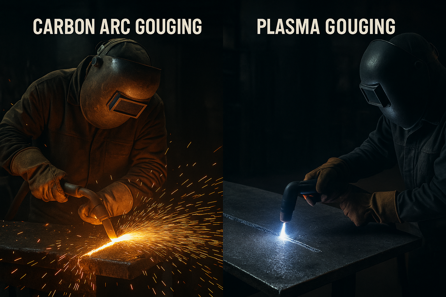
    Carbon arc gouging and plasma gouging both remove metal fastโ€”but they serve different jobs, budgets, and shop environments. This guide breaks down how each process works, when to use one over the other, and what to expect for performance, cost, and safety.


    Key Takeaways

    • Carbon arc gouging is cheaper to operate and works anywhere you have adequate air and amperage.
    • Plasma gouging (Hypertherm) delivers cleaner, more precise results with less post-grinding.
    • Plasma gouging has higher equipment cost but faster learning curve and less mess.
    • Carbon arc is loud, dirty, and requires high current; plasma is cleaner but more expensive to maintain.
    • For production shops and precision repair work, plasma wins. For heavy removal at lowest cost, carbon arc is still king.

    Where to Buy

    Arc Weld Store โ€“ Recommended:
    Carbon arc torches, gouging carbons, and air systems:
    https://www.arcweld.store/collections/esab-carbon-arc-slice-torch


    How Each Process Works

    Carbon Arc Gouging (CAC-A)

    Carbon arc gouging uses a graphite/carbon electrode to melt the base metal with high amperage while compressed air blows the molten metal away.

    Typical Specs (Manufacturer Ranges, AWS C5.3):

    • Current: 300โ€“1200 A depending on electrode size
    • Voltage: 35โ€“55 V
    • Air Pressure: ~80โ€“100 psi
    • Air Flow: ~20 cfm minimum
    • Electrode Types: DC+, copper-coated carbons
    • Noise: 110โ€“125 dB (hearing protection required)

    Strengths

    • Lowest equipment cost
    • Removes large volumes of metal quickly
    • Works indoors/outdoors, even in dirty field conditions
    • Repair shops & fab shops already wired for high amps

    Weak Points

    • Extremely loud
    • Heavy spatter and carbon dust
    • Large heat-affected zone
    • More grinding required after gouging

    Hypertherm Plasma Gouging

    Plasma gouging uses a constricted plasma arc to heat and remove metal with very controlled airflow. Hypertherm systems (Powermax series) are the industry standard.

    Typical Specs (Hypertherm Powermax):

    • Output: 45โ€“125 A depending on system
    • Gouge Depth: Light to medium removal
    • Air Pressure: ~90โ€“120 psi (per model spec sheet)
    • Duty Cycle: Model-dependent; most 60โ€“100% at rated output
    • Noise: Lower than carbon arc; still requires hearing protection

    Strengths

    • Very controlled and predictable gouge
    • Reduced post-grinding
    • Less carbon contamination
    • Quieter and cleaner than CAC-A
    • Works extremely well on stainless and aluminum

    Weak Points

    • Higher equipment cost
    • Consumables are more expensive
    • Not ideal for deep, aggressive removal
    • Requires dry, clean air supply

    Which One Should You Use?

    If you need maximum metal removal at lowest cost โ†’ Choose Carbon Arc Gouging

    Great for:

    • Heavy plate bevels
    • Removing welds on thick structural steel
    • Field repair
    • Shops already running 600โ€“1000 A power sources

    If you need cleaner, controlled gouges with minimal cleanup โ†’ Choose Hypertherm Plasma Gouging

    Great for:

    • Stainless & aluminum work
    • Pressure vessel repairs
    • Precision removal (cracks, isolated welds)
    • Indoor fabrication environments
    • Operators needing fast training curve

    Comparison Table

    Model/ProcessKey SpecsBest For
    CAC-A Carbon Arc Torch (Generic Industrial)300โ€“1200 A, 80โ€“100 psiHeavy gouging, lowest cost
    Hypertherm Powermax 65/85 Gouging65โ€“85 A plasma gouging, precise removalClean, controlled gouging

    Practical Considerations & Setup

    Air System Requirements

    Both processes require dry, steady airflow. Plasma is more sensitiveโ€”wet air destroys consumables.

    • Install a dryer or desiccant if plasma gouging.
    • Carbon arc tolerates โ€œshop airโ€ but still benefits from dryness.

    Power Requirements

    • Carbon arc requires sizable 3-phase machines or engine drives.
    • Plasma gouging can run on standard Hypertherm Powermax units (45โ€“125 A).

    Skill Level

    • Carbon arc demands better hand control to avoid digging.
    • Plasma gouging is easier to learn; the arc is more stable and directional.

    Safety Notes

    • Use ANSI Z87.1-rated eye protection (shade per AWS F2.2 recommendationsโ€”typically shade 10โ€“12 for CAC-A, 8โ€“10 for plasma).
    • Wear full PPE, flame-resistant clothing, and hearing protection (both processes exceed 100 dB).
    • Ensure adequate ventilation; carbon arc creates carbon dust and fumes.
    • Follow manufacturer guidelines for electrode size, air pressure, and duty cycle (Hypertherm, AWS C5.3 for CAC-A).

    FAQ

    Is plasma gouging as fast as carbon arc gouging?
    No. Plasma is cleaner and more controlled, but CAC-A removes metal significantly faster.

    Is carbon arc gouging bad for stainless?
    It can leave carbon contamination. Plasma is preferred for stainless/aluminum.

    Can you gouge outdoors with plasma?
    Yes, but wind can disrupt arc stability more than CAC-A.

    Does Hypertherm sell dedicated gouging consumables?
    Yesโ€”consult the Hypertherm Powermax series gouging nozzle and shield charts.


    Sources Checked

    • Hypertherm Powermax 45/65/85/105 Spec Sheets
    • AWS C5.3: Recommended Practices for Air Carbon Arc Cutting and Gouging
    • Manufacturer data for carbon electrodes and torches

    Where to Buy
    Arc Weld Store:

    https://www.arcweld.store/collections/esab-carbon-arc-slice-torch

  • Listen with Audible