
Washington Alloy 308L Welding Electrode 10 LB Stick Package – High Quality Stainless Steel Welding
$132.23 – 3/32" – 10 LBS.
In Stock
View Product
$132.23 – 3/32" – 10 LBS.
In Stock
View Product
Porosity in stick welding shows up as gas pockets in the weld metal. The usual causes are moisture, contamination, poor technique, or unstable shielding from the electrode. Use this checklist to isolate the cause before you change settings or replace parts.
If porosity keeps returning after cleaning and technique corrections, check whether the electrode matches the job. This draft includes one available product option from Weld Support Parts:
Product: Washington Alloy 308L Welding Electrode 10 LB Stick Package – High Quality Stainless Steel Welding
Use case: Stainless steel welding applications only as described by the product listing. Other compatibility details are Unknown (Verify).
Shopify handle: 308l-welding-electrode-10lb
Shortcode:
Elevate your welding projects with the Washington Alloy 308L-16 10lbs Welding Stick Electrode. Designed for stainless steel applications, this high-quality electrode ensures superior arc stability and a clean finish for every weld. Whether you're a professional welder or a DIY enthusiast, this product is a must-have in your welding toolkit. The 308L welding electrode is known for its excellent low carbon content,…
View at Arc Weld StoreNote: Confirm base material, procedure, polarity, and storage requirements before use.
It usually appears as small holes, pinholes, or worm-like voids in the weld bead or after grinding.
Yes. Moisture in the electrode, base metal, or surrounding environment is a common cause.
Not first. Check contamination, electrode condition, arc length, and ground quality before changing amperage.
Yes. A long arc increases exposure to air and can make porosity worse.
Start with electrode dryness, joint cleanliness, and arc length.
If porosity continues after these checks, stop and verify the procedure, consumable condition, and machine setup before production welding.
Undercut in stick welding appears as a groove melted into the base metal along the weld toe that is not filled properly by weld metal. It is commonly caused by excessive amperage, incorrect rod angle, excessive travel speed, poor weave control, or improper electrode manipulation. Undercut weakens weld strength, creates stress concentration points, and can cause weld rejection on structural and code work.
Field fix: Lower amperage slightly, shorten arc length, slow travel speed, and pause briefly at weave edges. Proper fix: Grind out severe undercut, correct the welding procedure, improve rod manipulation technique, and match electrode size to the joint geometry and material thickness.
Grinding out undercut creates sparks, debris, and airborne particles. Use proper eye protection, gloves, hearing protection, and ventilation during weld repair and cleanup operations.
Stick electrode sticking during arc start usually means the arc is not getting hot and stable fast enough to keep the rod from fusing to the work. The common causes are low amperage, poor scratch/tap technique, arc length too short, damp or damaged rods, wrong polarity, weak work clamp contact, undersized leads, low open-circuit voltage, or an electrode that is difficult to restart. 7018, small-diameter rods, cold plate, dirty base metal, and small inverter machines can make the problem more noticeable.
Do not keep twisting a stuck rod until the flux breaks off. Break the arc, free the rod, chip the stuck metal off the end, and restart on clean steel. If the electrode sticks again, increase amperage slightly within the rod range, clamp directly to clean metal, use a confident scratch start, lift immediately to a short arc, and verify rod storage and polarity before blaming the welder.
Related stick support checks include 7018 rod sticking causes, 7018 rod moisture contamination troubleshooting, electrode holder selection, and welding cable lead length and sizing.
| Symptom | Likely Cause | First Check |
|---|---|---|
| Rod sticks instantly on touch | Low amperage, poor strike, bad ground | Increase amps slightly and clean clamp point |
| Rod starts then goes out | Arc held too close or travel starts too slow | Lift to short arc immediately after strike |
| 7018 sticks repeatedly | Damp rod, low amps, wrong restart prep | Try fresh dry rod at correct range |
| Rod glows red near holder | Rod too small for amperage or held too long | Verify electrode diameter and current |
| Arc start is harsh and unstable | Wrong polarity, dirty metal, long leads | Check polarity, work return, and cable size |
| Only restarts stick | Slag cap on electrode end | Snap/clean the rod tip before restrike |
During a stick start, the electrode must touch or nearly touch the work long enough to ionize the gap, then separate enough to form an arc. If the current is too low, the rod coating is damp, the work clamp path is weak, or the operator holds the rod against the plate too long, the electrode bonds to the work before the arc stabilizes. Sticking is most often a setup-and-technique problem, but weak leads, poor connectors, wrong polarity, or a welder with low start performance can contribute.
7018 can be harder to restart than 6010, 6011, or 6013 because the flux can form an insulating cap at the rod end. For restart, snap the rod tip, file/scratch the end, or strike on a run-on area before returning to the joint. Use dry rods from proper storage. For code or critical low-hydrogen work, do not use questionable 7018 just because it will eventually start.
| Problem | Field Fix | Proper Fix |
|---|---|---|
| Rod sticks on first touch | Turn amperage up slightly | Set amperage by rod range and confirm ground/polarity |
| 7018 restart sticks | Break the flux cap and restrike | Use dry rods and proper restart technique |
| Weak arc from bad clamp | Move clamp to clean metal | Replace worn clamp, lug, or lead |
| Long leads reduce start | Shorten lead route | Use correctly sized cable and tight connectors |
| Damp rods stick | Use fresh rods | Store low-hydrogen rods in approved oven control |
Stick-start performance depends on the electrode, machine output, lead set, holder, and clamp. Verify rod classification, rod diameter, allowed polarity, welder AC/DC output, open-circuit voltage requirements, cable size, connector type, electrode-holder rating, and work-clamp rating before ordering parts. WSP accessory references such as Miller Thunderbolt 210 stick accessories and CST 282 stick lead sets and Tweco-style connectors show why lead and connector fitment must be verified.
Most Millermatic 255 pulse MIG setup problems come from a mismatch between the selected pulse program and the actual wire, gas, material, gun, or feed path. If the arc is harsh, ropey, cold, wandering, or spattery in pulse mode, first verify the screen selection: material/gas, wire diameter, and material thickness. Then check contact tip size, liner range, drive roll groove, gas blend, polarity, work clamp, and whether the installed MDX-250 gun uses AccuLock S or AccuLock MDX consumables.
Do not troubleshoot pulse MIG like basic short-circuit MIG. Pulse programs are built around a specific wire diameter and shielding gas. If the gas does not match the listed program, the machine may still weld, but arc length and arc control may need correction. If wire delivery is inconsistent, pulse mode will exaggerate the problem because the machine is trying to control a transfer pattern that the wire feed system is not supporting.
| Symptom | Likely Setup Cause | First Check |
|---|---|---|
| Arc feels long, lazy, or wandering | Arc length too high or wrong gas/program | Return arc length toward default and verify gas selection |
| Arc is harsh, narrow, or digging | Arc length too low or arc control too tight | Adjust in small steps after verifying program |
| Excess spatter in pulse mode | Wrong gas, wrong wire diameter, feed issue, or bad tip | Confirm selected wire/gas and replace tip |
| Ropey aluminum bead | Wrong aluminum program, poor feeding, or gun mismatch | Verify aluminum wire size, gun type, and gas |
| Burnback at the tip | Wire feed slowing before the arc | Inspect tip, liner, drive rolls, and spool brake |
| Program changes unexpectedly | EZ-Select gun enabled or wrong saved program | Check program mode and gun settings |
Pulse MIG controls current in a repeating high/low pattern so droplets transfer without running a constant high-energy spray arc. On the Millermatic 255, the operator still has to provide the correct setup inputs. The machine cannot fix a wrong gas bottle, a .035 program running .030 wire, a worn contact tip, a dirty liner, or poor work clamp contact.
Arc length is the first pulse tuning control to check. If the arc feels too long, unstable, or wide, reduce arc length gradually. If the arc feels too tight, harsh, or digging, increase arc length gradually. Large changes can make the machine feel worse, especially when the gas or wire selection is already wrong.
Arc control changes the width and character of the pulse arc cone. Use it after the basic program is correct. If you are using a gas that is not the gas listed for the selected pulse program, arc length and arc control may need adjustment, but they should not be used to hide a major gas mismatch.
For Millermatic 255 gun and consumable replacement, verify the installed gun before ordering. Weld Support Parts lists the Millermatic 255 with MDX-250 AccuLock S as the recommended replacement gun path on the Miller gun selection chart: Miller MIG Gun Selection Chart.
Use the correct consumable family for the gun that is actually installed. The Miller MDX-250 AccuLock S page lists MDX-250 AccuLock S guns and AccuLock S tips, nozzles, diffusers, and liners. The Miller MDX-250 AccuLock MDX page lists the AccuLock MDX version. Do not mix AccuLock S and AccuLock MDX contact tips or diffusers.
A field fix is to replace the contact tip, clean the nozzle, return arc length toward default, reselect the correct pulse program, straighten the gun lead, and clamp to clean metal.
The proper fix is to verify the entire setup chain: machine program, shielding gas, wire diameter, wire type, drive rolls, liner, contact tip, gun series, work lead, and saved program settings. If the machine still has setup errors, overtemperature messages, trigger errors, or unstable output after verified setup, send it to a qualified Miller service center.
Disconnect input power before servicing internal feeder parts, changing drive rolls, or inspecting internal connections. Keep fingers out of the drive rolls while jogging wire. Wear proper welding PPE and use adequate ventilation. Do not continue welding with damaged gun cable, cracked work lead, loose weld terminals, or repeated machine error messages.
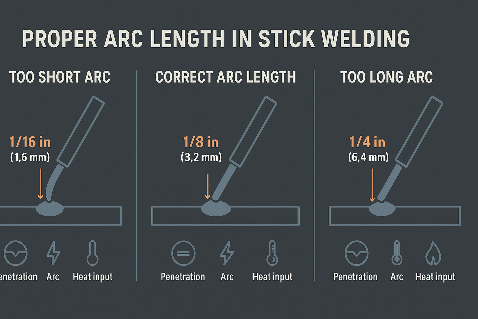
Arc length is one of the most important variables in stick welding, and this guide—Arc Control: Why Arc Length Matters in Stick Welding—breaks down exactly why. The book explains how arc length influences penetration, bead shape, stability, and overall weld quality. For new welders trying to stop sticking and wandering arcs, and for experienced welders chasing cleaner, more consistent beads, this resource provides straightforward direction.
This guide focuses entirely on understanding and maintaining proper arc length. Core topics include:
It’s written in plain language with enough detail to be useful without overwhelming beginners.
This guide fits welders who want more consistency and better quality out of their SMAW work. Ideal groups include:
Most welding books touch on arc length but don’t spend much time on it. This guide focuses specifically on that variable and explains it step-by-step. The visuals help welders understand what they should see, and the practical advice makes it easy to apply on the next weld.
For the best learning experience:
Arc Control: Why Arc Length Matters in Stick Welding is a solid resource for anyone wanting stronger, cleaner, and more consistent stick welds. It breaks down arc length in a way that welders can understand and apply immediately. Beginners and seasoned welders alike will find something useful here.
This article may contain Amazon affiliate links. We may earn a small commission at no extra cost to you.
