Tag: abrasives

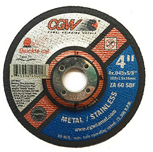
  • CGW 45001, Cut-Off Wheel 4″ x 5/8″, Type 27, Pack of (25): Product Breakdown

    CGW 45001, Cut-Off Wheel 4″ x 5/8″, Type 27, Pack of (25): Product Breakdown

    Product not found.
    “>CGW 45001, Cut-Off Wheel 4" x 5/8", Type 27, Pack of (25)

    The CGW 45001 cut-off wheel is a small-diameter abrasive wheel intended for cutting tasks in metal fabrication and maintenance work. The listed product data identifies it as a 4-inch wheel with a 5/8-inch center hole, Type 27 form, and pack quantity of 25. The available source data also identifies zirconia aluminum oxide abrasive, 60 grit, medium grade, and a maximum speed of 19,000 RPM. Use those details as the starting point for selection, setup, and inspection. Do not assume more than the source confirms.

    Key Takeaways

    • Confirm grinder arbor size before buying or mounting. This wheel is listed with a 5/8-inch center hole.
    • Confirm wheel type and application. Type 27 is commonly used for angle grinder work, but actual use depends on the tool, guard, and job.
    • Do not exceed the listed maximum speed of 19,000 RPM.
    • Inspect every wheel before use. Do not install cracked, chipped, or dropped wheels.
    • Use the wheel only for the material and cutting method supported by the source data. The listing states carbon and stainless steels. Other applications are Unknown (Verify).

    Product Breakdown

    The source product listing for CGW 45001, Cut-Off Wheel 4″ x 5/8″, Type 27, Pack of (25) identifies it as a CGW Abrasives wheel built with zirconia aluminum oxide abrasive. The wheel size is 4 inches in diameter with a 5/8-inch center hole. The wheel type is Type 27. Grit is listed as 60 and grade as medium. Maximum speed is listed as 19,000 RPM.

    That combination points to a wheel intended for general cutting support in shop and field maintenance work. The source specifically mentions cutting carbon and stainless steels. Anything beyond that is Unknown (Verify).

    How to Check Fit Before Use

    Before mounting this wheel, verify the grinder and accessory interface. Cutting wheel failures often start with the wrong size, wrong flange setup, or a damaged tool.

    • Check arbor size: Confirm the grinder arbor matches the 5/8-inch center hole.
    • Inspect the guard: Verify the guard is installed, secure, and positioned for cutting work.
    • Inspect flanges: Verify the flanges are clean, flat, and free of nicks or debris.
    • Check the speed rating: Verify the grinder’s no-load speed does not exceed 19,000 RPM.
    • Check the wheel face: Verify there are no cracks, chips, moisture damage, or edge damage before mounting.

    Installation and Setup Checks

    Use a simple pre-use routine. This helps reduce runout, wobble, and early wheel damage.

    1. Disconnect power before changing the wheel.
    2. Remove the old wheel and clean both flanges.
    3. Inspect the spindle, nut, and guard for damage.
    4. Install the new wheel without forcing it onto the arbor.
    5. Seat the wheel evenly between the flanges.
    6. Snug the retaining nut to the tool maker’s instructions. Do not overtighten.
    7. Spin the wheel by hand and verify it clears the guard and does not contact the work support.
    8. Run the tool briefly at no load and verify no abnormal vibration, noise, or wobble.

    Troubleshooting Cutting Problems

    If the wheel is not cutting cleanly, do not assume the wheel is defective. Check the setup and the work process first.

    Problem: Wheel vibrates or wobbles

    • Inspect: Look for a bent flange, dirty mounting surfaces, or a damaged wheel.
    • Verify: Confirm the center hole and arbor are the correct match.
    • Check: Make sure the wheel is seated flat and the nut is not cocked.
    • Action: Replace the wheel if it has been dropped or shows any damage.

    For more detail on vibration causes, see Cut-Off Wheel Vibration Troubleshooting: Grinder Wobble, Wheel Runout, Flange Problems, and Unsafe Cutting Symptoms.

    Problem: Slow cut or excessive pressure needed

    • Inspect: Check whether the wheel is loaded, glazed, or worn down.
    • Verify: Confirm the material is actually carbon steel or stainless steel if following the source guidance.
    • Check: Reduce side loading and keep the cut straight.
    • Action: Replace the wheel if cutting performance drops below acceptable shop standards.

    Problem: Wheel wears faster than expected

    • Inspect: Verify grinder speed and pressure technique.
    • Check: Avoid twisting, binding, or forcing the cut.
    • Verify: Confirm the wheel is appropriate for the workpiece thickness and cut method. If not, this is Unknown (Verify).

    How to Evaluate Whether This Wheel Fits the Job

    Maintenance buyers and supervisors should compare the task to the source data rather than rely on general assumptions. Use this wheel as a candidate when you need a 4-inch Type 27 wheel with a 5/8-inch bore and a 19,000 RPM limit. The source says it is for carbon and stainless steels. If the job involves another alloy, a different grinder class, or a special cutting method, verify compatibility before issue.

    If you need help understanding Type 1 versus Type 27 cut-off wheel selection, review Type 1 and Type 27 Cut-Off Wheels: Pros, Cons, and Applications.

    Safety Notes

    • Wear eye protection, face protection, hearing protection, gloves, long sleeves, and suitable clothing.
    • Keep the guard installed. Do not run abrasive wheels unguarded.
    • Do not use a damaged wheel.
    • Do not exceed the listed maximum RPM.
    • Keep hands out of the cut line and avoid side loading unless the wheel and tool setup support it. If uncertain, verify with the tool maker’s instructions.
    • Stop immediately if the wheel develops cracking, vibration, or unusual sound.

    FAQ

    Is the CGW 45001 wheel for stainless steel?
    The source listing states it is for cutting carbon and stainless steels. Verify the exact stainless grade and job conditions before use.

    What grinder does it fit?
    The source provides a 5/8-inch center hole and a 4-inch diameter. Exact tool compatibility is Unknown (Verify). Match the arbor, guard, and speed rating to the grinder manufacturer’s instructions.

    Can this wheel be used above 19,000 RPM?
    No. The source lists a maximum of 19,000 RPM. Do not exceed that value.

    What does Type 27 mean here?
    Type 27 is the wheel form listed by the source. Use it only when the grinder, guard, and application are suitable. For a broader breakdown of Type 27 use, verify against the tool and wheel manufacturer data.

    Sources Checked

    Note: All uncertain compatibility and application details are marked as Unknown (Verify). Do not infer approvals or certifications not stated in the source data.

    Related Arc Weld Part

    CGW 45001, Cut-Off Wheel 4" x 5/8", Type 27, Pack of (25)

    CGW 45001, Cut-Off Wheel 4" x 5/8", Type 27, Pack of (25)

    CGW Abrasives 45001 Cut-Off Wheel 4" x 5/8" 60 Grit Type 27 Zirconia Aluminium Oxide General purpose cutting wheel. Zirconia grain for faster cutting and longer life. For cutting carbon and stainless steels. Specification: BRAND: CGW Abrasives ABRASIVE MATERIAL: Zirconia Aluminum Oxide GRIT: 60 GRADE: Medium DIAMETER INCHES: 4 CENTER HOLE DIAMETER INCHES: 5/8 MAX RPM: 19000 WHEEL TYPE: Type 27 TOOL COMPATIBILITY:…

    View at Arc Weld Store

    Related Weld Support Guides

  • Choosing Flap Disc Grit for Weld Blending

    Choosing Flap Disc Grit for Weld Blending

    CK26 TIG Torch Support

    Choosing the right flap disc grit weld blending work depends on what you are trying to remove, how much metal you can afford to take off, and what finish you need at the end of the pass. The wrong grit can leave deep scratches, unnecessary heat, or a profile that takes longer to correct. The right grit reduces rework and keeps the blend controlled.

    This guide is for welders, fabricators, maintenance buyers, and support teams who need a practical way to select flap disc grit for weld cleanup and blending. It does not assume one grit fits every joint. Start with the weld condition, then choose the least aggressive disc that will still do the job.

    Key Takeaways

    • Use coarse grit for heavy weld crowns, slag, or spatter cleanup when stock removal is the priority.
    • Use medium grit for blending weld toes and reducing scratch depth before finish work.
    • Use finer grit when the weld is already close to profile and the goal is surface refinement.
    • Check weld metal, base metal, and heat input often. A flap disc can remove material faster than expected.
    • Verify the finish requirement before starting. A cosmetic target is different from a paint-prep target or a fabrication cleanup target.

    Start With the Weld Condition

    Before choosing grit, inspect the weld. Ask three questions:

    • How much crown is above the base material?
    • Is the issue mainly spatter, oxide, or actual weld profile?
    • Is the goal to blend only, or to blend and prep for coating?

    If the weld is tall or irregular, a more aggressive grit may be needed at the start. If the bead is already close to the final profile, jumping straight to a coarse disc can cut too deep and widen the blend zone.

    General Grit Selection Logic

    Manufacturers label flap disc grit by abrasive grade, but the practical choice is usually based on stock removal versus finish quality.

    • Coarse grit: Best for heavy blending, weld crown knockdown, and initial cleanup.
    • Medium grit: Common for normal weld blending when you need control and a cleaner scratch pattern.
    • Fine grit: Better for finishing passes where the weld is nearly flush and visible surface marks matter.

    If you are unsure, begin with the least aggressive grit that can still remove the defect. You can always step down to a finer disc. Starting too coarse often creates a larger repair area than necessary.

    Practical Check / Inspect / Verify Steps

    Check the weld shape, material thickness, and surrounding finish requirement. Note whether the work is on carbon steel, stainless, or another base metal. Do not assume the same grit behaves the same way across all materials.

    Inspect the disc before use. Confirm the abrasive condition, edge wear, and backing condition. A damaged flap disc can chatter, load up, or cut unevenly.

    Verify the required blend depth. If the print, supervisor, or customer spec calls for a minimal profile change, use a test pass and measure before continuing.

    Check the scratch pattern after the first pass. If the disc is leaving deep grooves that will need extra finishing, step up to a finer grit sooner rather than later.

    Inspect heat build-up during long blends. Excess heat can discolor material, affect nearby coating, and make the finish harder to control.

    Verify that the final surface meets the downstream step: paint, coating, sealant, or final assembly. The required finish for coating prep is not the same as a visible cosmetic weld finish.

    Troubleshooting Common Problems

    Problem: The disc removes too much material

    Possible cause: Grit is too coarse for the weld condition, or pressure is too high.

    • Reduce hand pressure.
    • Step to a finer grit.
    • Use shorter passes and recheck the profile.

    Check: Measure the blend zone width after each pass.

    Verify: You are not grinding past the intended repair area.

    Problem: Scratch pattern is too deep

    Possible cause: The disc is correct for removal but too aggressive for the finish stage.

    • Switch to a medium or fine grit.
    • Change the pass direction to reduce visible marks.
    • Use a lighter touch on the final pass.

    Inspect: Whether the earlier pass left ridges that need a controlled follow-up.

    Verify: The finish requirement does not call for polishing when only blending is needed.

    Problem: Disc loads up or cuts inconsistently

    Possible cause: Material type, coating residue, or contamination may be affecting cut behavior. Exact cause is Unknown (Verify).

    • Stop and inspect the work surface.
    • Confirm the disc is appropriate for the base material.
    • Replace the disc if it is worn or loaded.

    Check: Whether oil, paint, or scale is present on the surface.

    Verify: The disc is intended for the application before resuming work.

    How to Match Grit to the Job

    For weld blending, the decision usually comes down to one of three work types:

    • Heavy correction: Start coarse, then move to medium if the profile gets close.
    • Normal blending: Start medium and adjust based on scratch depth and removal rate.
    • Finish refinement: Start fine if only minor marking remains and the weld is already near flush.

    When a job requires multiple passes, do not treat each pass the same. The first pass removes the shape. The next pass controls the surface. The final pass should be judged by the finish requirement, not by how fast the disc cuts.

    WSP Lookup Section

    Weld Support Parts currently provides the following lookup page that may be relevant to support-side welding workflows and routing considerations:

    CK26 TIG Torch Support

    Page details provided in the source set: CK26 TIG torch support with Series 3 breakdown routing. Any deeper compatibility or installation detail is Unknown (Verify). Review the page directly before using it in a purchasing or support decision.

    Safety Notes

    • Wear eye protection, hand protection, hearing protection, and appropriate respiratory protection for grinding work.
    • Keep the workpiece secured before starting the disc.
    • Do not force the disc into the weld. Excess pressure increases heat and reduces control.
    • Allow the disc to stop fully before setting the tool down.
    • Inspect the wheel, tool guard, and work area before use. Tool-specific requirements may vary and are Unknown (Verify).

    FAQ

    What grit should I start with for weld blending?

    Start with the least aggressive grit that will still remove the weld shape you need to correct. For heavy weld crowns, that may be coarse. For moderate blending, medium is often enough. If the weld is already close to flush, start finer.

    Can one flap disc grit handle every weld blending job?

    No. The right grit depends on the amount of stock removal, the base material, and the finish requirement. Using one grit for every job usually leads to either over-grinding or extra finishing work.

    How do I know when to switch to a finer grit?

    Switch when the weld profile is close and the remaining job is surface refinement. If the disc is leaving deeper scratches than the next process can accept, move to a finer grade.

    Does a finer grit always give a better finish?

    Not always. A finer grit gives a smoother scratch pattern, but it removes material more slowly. If the weld still needs shape correction, a fine disc may waste time and wear out faster.

    Sources Checked

    Note: Specific performance claims, compatibility details, and material-specific cut behavior beyond the provided sources are Unknown (Verify).

    Disclosure: As an Amazon Associate, Weld Support Parts may earn from qualifying purchases.

    Related Weld Support Guides

  • Flap Disc Edge Wear Troubleshooting

    Flap Disc Edge Wear Troubleshooting

    Flap disc edge wear usually happens when the grinder angle is too steep, pressure is excessive, the wrong disc type is being used, or the operator is grinding primarily on the disc edge instead of the face. Premature edge wear reduces abrasive life, creates uneven grinding performance, increases heat buildup, and can damage both the workpiece and grinder.

    Common Symptoms

    • Outer edge of the flap disc wears much faster than the center.
    • Grinding becomes uneven or difficult to control.
    • Disc cuts aggressively at first but loses performance quickly.
    • Visible flap tearing or uneven flap separation.
    • Increased vibration during grinding.
    • Excessive heat discoloration on the workpiece.

    Likely Causes

    • Grinding angle too steep: Excessive angle concentrates force on the outer edge of the disc.
    • Too much pressure: Heavy force overheats and overloads the abrasive flaps.
    • Incorrect flap disc style: Type 27 and Type 29 discs perform differently depending on grinding angle and application.
    • Wrong grit selection: Coarse grits used for finishing work can wear unevenly.
    • Improper grinder RPM: Overspeeding increases edge stress and heat generation.
    • Using the edge like a grinding wheel: Flap discs are designed primarily for face contact, not aggressive edge digging.

    Inspection Steps

    1. Inspect flap wear pattern across the full disc face.
    2. Verify grinder RPM matches the flap disc rating.
    3. Check grinding angle during operation.
    4. Inspect for excessive heat discoloration or flap glazing.
    5. Verify correct flap disc style and grit for the application.
    6. Inspect grinder spindle and backing flange condition.

    Visual Wear Indicators

    • Outer edge worn down faster than the center.
    • Missing or torn abrasive flaps.
    • Glazed abrasive surface from overheating.
    • Uneven flap height around the disc.
    • Discoloration from excessive grinding heat.

    Common Wrong-Part Mistakes

    • Using Type 27 discs where Type 29 geometry is more appropriate.
    • Running flap discs above rated RPM.
    • Using coarse grinding discs for fine finishing applications.
    • Using worn backing flanges that create disc instability.

    Field Fix vs Proper Fix

    Field fix: Reduce grinding pressure, flatten the grinder angle slightly, and rotate the disc contact area more evenly. Proper fix: Select the correct flap disc geometry, grit, RPM range, and grinder setup for the application while correcting operator technique issues.

    Ignored Failure Consequences

    Ignoring uneven edge wear reduces abrasive life, increases grinding cost, creates inconsistent surface finish quality, overheats the workpiece, and increases vibration-related grinder wear.

    Safety Notes

    Always follow abrasive RPM ratings and grinder compatibility requirements. Use face shields, gloves, hearing protection, and safety glasses when grinding. Never use damaged or delaminating flap discs.

    Sources Checked

    • Norton abrasive solutions catalog
    • Weiler abrasive catalog
    • Lincoln welding accessories catalog
  • Grinding Wheel Wobble Causes and Troubleshooting

    Grinding Wheel Wobble Causes and Troubleshooting

    A grinding wheel that wobbles during operation is usually caused by damaged flanges, incorrect wheel mounting, bent spindles, worn bearings, improper wheel storage, or using the wrong wheel for the grinder. Even minor wheel runout can reduce grinding accuracy, overload bearings, increase vibration, and create a dangerous wheel failure risk at operating RPM.

    Common Symptoms

    • Visible side-to-side wheel movement during rotation.
    • Vibration through the grinder body or handle.
    • Uneven grinding marks or gouging.
    • Premature edge wear on flap discs or grinding wheels.
    • Difficulty maintaining straight cuts.
    • Excessive operator fatigue from vibration.

    Likely Causes

    • Improper wheel mounting: Dirt, burrs, or metal debris trapped behind the wheel prevent proper seating.
    • Damaged mounting flanges: Bent or worn flanges create uneven clamping pressure.
    • Bent spindle shaft: Impact damage from dropped grinders commonly bends spindle assemblies.
    • Worn grinder bearings: Bearing play allows oscillation under load.
    • Wheel damage: Cracked, warped, moisture-damaged, or expired wheels may not rotate true.
    • Incorrect wheel selection: Oversized or incompatible wheels create instability and imbalance.

    Inspection Steps

    1. Disconnect grinder power before inspection.
    2. Remove the wheel and clean both flange surfaces completely.
    3. Inspect the abrasive wheel for cracks, chips, or uneven wear.
    4. Check spindle runout manually while rotating the shaft slowly.
    5. Verify wheel RPM rating exceeds grinder RPM.
    6. Inspect arbor fitment and mounting hardware compatibility.

    Common Wrong-Part Mistakes

    • Installing wheels with incorrect arbor sizes.
    • Running cut-off wheels sideways as grinding wheels.
    • Using missing or incorrect flange washers.
    • Using moisture-damaged abrasive wheels from poor storage.

    Field Fix vs Proper Fix

    Field fix: Remove and remount the wheel correctly, clean flange surfaces, and replace visibly damaged abrasives. Proper fix: Replace bent spindles, worn bearings, damaged flanges, or incorrect wheel assemblies. Persistent wobble should never be ignored on high-speed grinders.

    Ignored Failure Consequences

    Operating with a wobbling grinding wheel increases the chance of wheel breakage, grinder damage, poor surface finish, operator fatigue, and severe injury from abrasive wheel fragmentation.

    Safety Notes

    Always follow abrasive RPM ratings and mounting instructions. Never use cracked wheels. Use face shields, gloves, hearing protection, and safety glasses when troubleshooting grinders and abrasive equipment.

    Sources Checked

    • Norton welding abrasive solutions catalog
    • Weiler abrasive and surface conditioning catalog
    • Lincoln Electric welding accessories catalog
  • Read with Kindle Unlimited