• Why Your MIG Contact Tip Burns Back (And How to Fix It in 10 Minutes)

    Wire burning back into your contact tip kills productivity. You’ll see spatter buildup, stuck wire, and weak arc quality. This happens because of wire-feed speed, hose tension, or tip wearโ€”and it’s fixable.

    Key Takeaways

    • Fix in 10 minutes: Adjust wire speed or replace the contact tip ($5โ€“$15)
    • Root cause: Wire speed too low, hose slack, or worn tip
    • Prevention: Check stick-out distance (3/8″) and keep hose straight
    • Cost: $5โ€“$50 depending on the fix (adjustment is free)

    Quick Diagnosis

    What you’ll see:

    • Wire fused or stuck inside the copper contact tip
    • Spatter buildup around the tip and nozzle
    • Weak or inconsistent arc
    • Wire stops feeding mid-weld

    Likely causes (ranked by frequency):

    1. Wire-feed speed set too low
    2. Contact tip worn or undersized
    3. Hose kinked or slack (wire burns back during arc)
    4. Stick-out distance too long (>1/2″)
    5. Liner clogged or damaged

    Safety Notes

    • Disconnect power before removing or inspecting the gun
    • Wear leather gloves when handling hot tips or spatter
    • Check shielding gas flow (proper flow prevents arc instability that causes burnback)
    • Ventilate the work area (MIG spatter and fumes require good airflow per ANSI Z87.1)

    Step-by-Step Troubleshooting

    Step 1: Check wire-feed speed (2 minutes)

    • Set speed to match your wire diameter and material (typically 200โ€“400 ipm for .035″ mild steel)
    • If too low, wire can’t keep up with the arc and burns back
    • Increase speed by 10โ€“20% and test

    Why: Wire speed controls how fast wire feeds. Too slow = burnback. Too fast = bird nesting.

    Step 2: Inspect the contact tip (3 minutes)

    • Remove the nozzle and tip (use a contact-tip wrench or pliers)
    • Look inside the bore for spatter or wear
    • If the hole is enlarged or clogged, the tip is done

    Why: Worn tips have loose contact and cause arc instability.

    Step 3: Check hose routing (2 minutes)

    • Trace the gun cable from the feeder to the gun
    • Look for kinks, tight bends, or slack sections
    • Straighten any kinked areas; slack hose lets wire move too freely

    Why: Slack hose = wire bounces during feed, causing burnback.

    Step 4: Verify stick-out distance (1 minute)

    • Measure from the end of the nozzle to the base metal
    • Should be 3/8″ to 1/2″ for MIG
    • If longer, the arc is too far from the tip and wire overheats

    Why: Long stick-out = high resistance = heat buildup = burnback.

    Fix Options (Ranked)

    1. Adjustment (Free)

    • Increase wire-feed speed by 10โ€“20%
    • Straighten hose and secure with cable ties
    • Reduce stick-out distance to 3/8″
    • Test on scrap metal

    2. Consumable Change (~$5โ€“$15)

    • Replace contact tip with correct size (check gun manual for .030″ or .035″)
    • Clean liner with a wire-brush kit
    • Replace if liner is kinked

    3. Part Replacement (~$20โ€“$50)

    • Replace entire nozzle and tip assembly
    • Replace gun cable if hose is damaged
    • Upgrade to a heavier-duty gun for high-duty-cycle work

    Recommended Fix (Product Section)

    A quality contact-tip cleaner kit prevents burnback by keeping tips clean and helping you identify wear early. The Herain Welding Tip Cleaner includes 12 wire sizes to clean and inspect tips before they fail.

    Why it works: Clean tips maintain good electrical contact. Worn tips show immediatelyโ€”you’ll replace them before burnback happens.

    When to use it: After every 8โ€“10 hours of welding, or whenever you notice spatter buildup.

    When NOT to use it: If the tip bore is enlarged or damaged, cleaning won’t helpโ€”replace it instead.

    What to check before buying:

    • Verify your gun type (MIG, TIG, plasmaโ€”this kit covers MIG/TIG)
    • Confirm tip size (.030″, .035″, or .040″)
    • Ensure you have a contact-tip wrench or pliers
    • Check that your nozzle is removable (most are)
    Herain Welding Tip Cleaner, Carb Carburetor Cleaner and Torch Nozzle Tip Cleaner Set for Cleaning Engine Carburetors, Gas Orifices, Sprinklers, Shower Heads(12 Wire Set Plus a Flat File) (1)
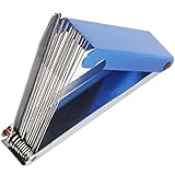
    • 1.High-quality materials: The carbohydrate cleaning tool is made of high-quality stainless steel, and is equipped with a lightweight and stable high-quality aluminum box, it is a good tool to carry and use
    • 2.Different diameters: There are 13 kinds of carburetor cleaning kits (0.4, 0.5, 0.6, 0.7, 0.8, 0.9, 1.0, 1.1, 1.2, 1.4, 1.5, 1.6 mm, a flat file) with different diameters, specially used to remove tiny Dirt in the nozzle and carburetor channels
    • 3.Widely used: Welding gun nozzle cleaning tool can be used to clean small orifices such as spray guns, nozzles, pneumatic tools, camping stoves and so on; it is also suitable for most automobiles, motorcycles, ATV, welding machines, tattoo machines, lawn equipment and other power sports carburettor
    • 4.Easy to use: Torch tip cleaner is spiral, it is a special tool used to dredge the cutting nozzle due to the splash of residue during the cutting process. Frequent dredging can make the cutting nozzle more resistant and better cutting effect
    • 5.Ingenuity: As long as the tip cleaner is used correctly, it can be used multiple times. If you have any product questions, you can contact us at any time

    Last update on 2026-05-05 / Affiliate links / Images from Amazon Product Advertising API

    Comparable Options

    Lincoln Electric K3724-1 Industrial Tip Cleaner (~$12): Heavy-duty option with file and pick. Best for high-volume shops. https://www.amazon.com/dp/B0BL1DG3FR?tag=weldsupport-20

    WILLBOND 4-Piece Torch Tip Cleaner Kit (~$10): Budget-friendly with 13 wire sizes. Good for occasional use. https://www.amazon.com/dp/B089B2FBCN?tag=weldsupport-20

    Common Mistakes

    • Setting wire speed too low to “save wire”: You’ll waste more time fixing burnback than you save on consumables.
    • Ignoring a kinked hose: Slack hose is the #1 cause of burnback. Straighten it immediately.
    • Using the wrong tip size: A .030″ tip on .035″ wire won’t feed properly. Check your gun manual.
    • Not cleaning the liner: A clogged liner causes friction, which leads to burnback and bird nesting.
    • Leaving the nozzle on while cleaning the tip: You can’t see spatter buildup if the nozzle is in the way.

    FAQ (Snippet-Optimized)

    Q: Why does my wire keep sticking in the tip? A: Wire speed is too low, hose is slack, or the tip is worn. Increase speed by 10โ€“20%, straighten the hose, and replace the tip if the bore is enlarged.

    Q: How often should I replace my contact tip? A: Every 50โ€“100 hours of welding, or sooner if you see spatter buildup or burnback. Clean it every 8โ€“10 hours.

    Q: Can I fix a burnt-back tip by cleaning it? A: No. If wire is fused inside, the tip is damaged and must be replaced. A cleaner kit helps prevent burnback, not fix it.

    Q: What’s the right wire-feed speed for MIG? A: For .035″ mild steel, start at 250โ€“300 ipm. Adjust based on your material and thickness. Check your machine manual for exact settings.

    Q: Does shielding gas affect burnback? A: Yes. Low gas flow or wrong gas mix causes arc instability, which can trigger burnback. Verify flow rate (15โ€“20 cfh for MIG) and use the correct gas (75% Ar / 25% CO2 for mild steel).

    Next Steps

    Related troubleshooting posts:

    For more welding fixes and gear options, see our full resource page:https://blog.weldsupportparts.com/links/

  • TIG Gas Lens Cups Cracking? Replace Them Before Porosity Hits

    Intro

    Your TIG welds are starting to show porosity or inconsistent gas coverage. You’ve checked your argon flow, regulator pressure, and torch angle. Everything checks outโ€”except the welds still look rough.

    The problem might be hiding in plain sight: a cracked or worn gas lens cup.

    A damaged gas lens cup disrupts shielding gas flow, allowing air to contaminate the weld pool. Even a hairline crack can cause porosity that ruins structural welds. Unlike contact tips, gas lens cups get less attentionโ€”but they’re just as critical.

    Key Takeaways

    • Cracked or worn gas lens cups allow air into the shielding gas stream
    • Porosity, discoloration, and rough beads are signs of gas coverage failure
    • Gas lens cups wear faster with high amperage or prolonged duty cycles
    • Replacement is quick and inexpensiveโ€”$2โ€“$8 per cup
    • Proper fitment requires matching your torch size and collet type

    The Problem

    A gas lens cup (also called a ceramic cup or nozzle) sits at the end of your TIG torch and directs shielding gas around the weld pool. Over time, thermal cycling and spatter impact cause:

    • Cracks: Hairline fractures that let air seep in
    • Erosion: The ceramic wears thin, reducing gas flow efficiency
    • Discoloration: Brown or white deposits indicate heat stress and gas leakage
    • Porosity: Air contamination creates gas pockets in the weld

    A cracked cup might look minor, but even a 1mm hairline fracture is enough to ruin a structural weld.

    Why It Matters

    Porosity from a bad gas lens cup is expensive:

    • Rework: Cutting out and re-welding porosity costs hours of labor
    • Inspection failures: Radiographic or ultrasonic testing will reject porosity
    • Safety risk: Porosity weakens the joint and can cause failure under load
    • Material waste: Scrap parts and wasted filler material
    • Reputation: Failed welds on customer parts damage trust

    A $5 replacement cup prevents all of this.

    The Fix

    Replace your gas lens cup as part of routine torch maintenance:

    1. Stop the welder and let the torch cool (5โ€“10 minutes for high-amperage work)
    2. Unscrew the nozzle from the torch head (usually hand-tight or with a small wrench)
    3. Remove the collet body (the small metal piece holding the cup)
    4. Slide out the old cup and inspect the collet body for damage
    5. Install the new cup (check the size: 3/8″, 7/16″, 1/2″, etc.)
    6. Re-assemble: Collet body โ†’ new cup โ†’ nozzle
    7. Hand-tighten and resume welding

    Total time: 3โ€“5 minutes.

    Why This Product Solves It

    The CK TIG Gas Lens Collet Body (available in multiple sizes) is a precision replacement for standard TIG torches (#17, #18, #26). It includes the collet body and gas lens cup assembly, ensuring proper gas flow and consistent shielding.

    Key benefits:

    • Precision fit: Engineered for standard torch sizes
    • Improved gas coverage: Larger diameter design provides better shielding gas distribution
    • Durability: Quality ceramic resists thermal cracking
    • Compatibility: Works with most standard TIG torches
    • Affordable: Packs of 2 cover extended service intervals

    Replace every 100โ€“200 hours of welding or immediately if you see porosity or discoloration.

    What to Check Before You Buy

    • Torch size: Standard torches are #17, #18, or #26 (small torches are #9, #20, #24W, #25)
    • Cup size: Available in 3/8″ (3/32″), 7/16″ (1/8″), 1/2″ (5/32″), and larger
    • Collet type: Standard collet body vs. gas saver (gas saver is more efficient but less common)
    • Fitment: Unknown (Verify) โ€” confirm your torch model and cup size before ordering

    Real-World Use

    A stainless steel fabrication shop doing heavy TIG work at 150โ€“200 amps noticed porosity on every other weld. They replaced the gas lens cup and the porosity disappeared. The old cup had a hairline crack invisible to the naked eye. Now they replace cups every 150 hours as preventive maintenance.

    Common Mistakes

    • Ignoring discoloration: Brown or white staining on the cup is a sign of gas leakageโ€”replace it immediately
    • Wrong cup size: Installing a 3/8″ cup on a 1/2″ collet body leaves gaps and allows air in
    • Over-tightening the nozzle: Hand-tight is enough; over-tightening can crack the cup
    • Not cleaning the torch head: Spatter and oxidation on the torch head can interfere with gas flowโ€”clean it when you replace the cup
    • Waiting for complete failure: Replace cups at the first sign of porosity, not after multiple failed welds

    Safety Notes

    • Always wear ANSI Z87.1-rated safety glasses or a helmet when welding
    • Let the torch cool for 5โ€“10 minutes before removing the cupโ€”ceramic cups retain heat and can cause burns
    • Ensure proper ventilation; TIG welding produces fumes that require respiratory protection (OSHA guidelines)
    • Never touch the cup or nozzle immediately after welding

    Always follow the manufacturer’s instructions and your shop’s safety procedures. If you’re unsure about fitment or ratings, verify before you buy or install.

    Where to Buy

    Available at ArcWeld.store (stock and shipping: Unknown โ€“ verify)

  • Worn MIG Contact Tips Causing Porosity? Here’s the Fix

    Intro

    Your MIG welds are coming out porous, weak, or with inconsistent penetration. You’ve checked your gas flow, wire speed, and voltageโ€”everything looks right. The culprit? A worn contact tip.

    A degraded contact tip creates poor electrical contact with the wire, causing arc instability and incomplete fusion. This is one of the most overlooked failure points in MIG welding, and it’s costing you time and rework.

    Key Takeaways

    • Worn contact tips cause porosity, spatter buildup, and weak welds
    • Signs: Pitting, erosion, or a loose fit on the wire
    • Replace every 50โ€“100 hours of welding or when you notice performance drop
    • Proper fitment matters: match your wire size (.023″, .030″, .035″, .045″)
    • Quality replacement tips prevent downtime and improve weld quality

    The Problem

    A contact tip is a consumable that wears with every pass. As current flows through it to the wire, the tip gradually erodes and pits. When it gets too worn, it can’t maintain consistent electrical contact, causing:

    • Arc instability: Erratic arc behavior, spatter, and poor fusion
    • Porosity: Gas pockets trapped in the weld due to arc interruption
    • Weak beads: Inconsistent penetration and bead profile
    • Spatter buildup: Excess spatter around the nozzle area

    Most shops don’t replace tips until they fail completelyโ€”by then, you’ve already scrapped parts.

    Why It Matters

    Worn contact tips don’t just make bad welds; they cost money:

    • Rework: Porosity and weak fusion mean cutting out bad sections and re-welding
    • Downtime: Troubleshooting a worn tip wastes 30 minutes to hours
    • Material waste: Scrap parts and wasted filler material add up fast
    • Safety: Weak welds on structural or pressure-bearing work are a liability

    A $5โ€“$15 contact tip replacement takes 2 minutes and prevents all of this.

    The Fix

    Replace your contact tip as part of routine maintenance:

    1. Stop the welder and let it cool for 30 seconds
    2. Unscrew the nozzle (usually 1/2″ or 5/8″ wrench)
    3. Remove the old tip by hand or with a tip puller
    4. Install the new tip hand-tight, then snug with the nozzle
    5. Re-install the nozzle and resume welding

    That’s it. Total time: under 2 minutes.

    Why This Product Solves It

    The Bernard AccuLock S Contact Tip is a direct replacement for Miller AccuLock S guns (MDX-100, MDX-250, and compatible systems). It maintains precise electrical contact with the wire, delivering stable arc and consistent penetration.

    Key benefits:

    • Exact fitment: Engineered for AccuLock S gunsโ€”no guessing
    • Reliable contact: Precision-molded for tight wire fit and stable arc
    • Affordable: Pack of 10 tips covers months of welding
    • Compatible: Works with .030″, .035″, and .045″ wire (check your size)

    Replace every 50โ€“100 hours or when you notice spatter or porosity. Preventive replacement beats troubleshooting a failed tip mid-job.

    What to Check Before You Buy

    • Your gun type: This is for Miller AccuLock S guns (MDX-100, MDX-250). If you use a Lincoln, ESAB, or Tweco gun, you need a different tip
    • Wire size: Available in .030″, .035″, and .045″โ€”match your setup
    • Quantity: Pack of 10 is standard; one tip lasts 50โ€“100 hours depending on duty cycle
    • Fitment: Unknown (Verify) โ€” confirm your gun model before ordering

    Real-World Use

    A fabrication shop running steady MIG work replaces contact tips every 2โ€“3 weeks. One worn tip caused 4 hours of rework on a structural assembly before they realized the problem. Now they replace tips every 50 hours as preventive maintenance. No more porosity, no more downtime.

    Common Mistakes

    • Waiting too long to replace: Worn tips degrade weld quality for days before failing completely
    • Wrong size: Installing a .035″ tip in a .045″ gun (or vice versa) causes loose fit and arc instability
    • Not cleaning the nozzle: Spatter buildup on the nozzle can also cause arc issuesโ€”clean it when you replace the tip
    • Over-tightening: Hand-tight is enough; over-tightening can crack the tip
    • Ignoring porosity: If you see porosity, replace the tip immediatelyโ€”it’s the first thing to check

    Safety Notes

    • Always wear ANSI Z87.1-rated safety glasses or a helmet when welding
    • Let the gun cool for 30 seconds before removing the nozzleโ€”contact tips can retain heat
    • Ensure proper ventilation; MIG welding produces fumes that require respiratory protection (OSHA guidelines)
    • Never touch the tip or nozzle immediately after weldingโ€”they will cause burns

    Always follow the manufacturer’s instructions and your shop’s safety procedures. If you’re unsure about fitment or ratings, verify before you buy or install.

    Where to Buy

    Available at ArcWeld.store (stock and shipping: Unknown โ€“ verify)

  • YESWELDER Auto-Darkening Helmet LYG-L600A: True Color Lens Review & Buying Guide

    An auto-darkening helmet is one of the best investments for any welder. The YESWELDER LYG-L600A delivers true-color optics, solar power backup, and two arc sensors at a price that won’t break the bank. Here’s what you need to know before buying.

    Key Features at a Glance

    • True Color 1/1/1/1 optics: Minimal color distortion for accurate weld pool visibility.
    • Shade range 3.5/9โ€“13: Covers TIG, MIG, stick, and grinding.
    • 2 arc sensors: Faster response than single-sensor helmets.
    • Solar + battery power: Dual power ensures operation even if batteries die.
    • Lightweight design: 1.85 lbs with adjustable headgear for all-day comfort.
    YESWELDER Auto Darkening Welding Helmet, Blue Light Blocking, 1/1/1/1 True Color Solar Powered Welding Hood with 2 Arc Sensors, Wide Shade 3.5/9-13 Welder Mask for TIG MIG ARC and Grind
    • Advanced Eye Protection with Blue Light Blocking Technology: This welding helmet features cutting-edge Blue Light Blocking outer lens, shielding your eyes from harmful blue light during welding, protects your eyes by filtering out most of harmful high energy blue light rays while letting through the less harmful portion of the blue light spectrum. This ensures long-lasting eye comfort and safety, making it ideal for extended welding sessions
    • Multi-Application: Wide shade range 3.5/9-13, covering most common welding processes, ideal for TIG, MIG, MMA (Stick), and GRIND. Easily accommodates magnifying lenses for close-up work
    • True Color & Clear View: This auto darkening welding helmet is equipped with standard 3.64″X1.67″ viewing area, enjoys a true color view with upgraded 1/1/1/1 optical clarity, improves visibility and reduced eye strain
    • Fast Auto-darkening: 2 premium arc sensors trigger darkness in 1/30000 sec. Features adjustable sensitivity and delay controls for optimal performance in any lighting/arc condition
    • Long Service Life: Powered by solar panel technology and replaceable CR2450 lithium battery. Solar panel can transform harmful arcs into electrical energy not only for longer life, but also provides support for energy conservation and environmental protection

    Last update on 2026-05-05 / Affiliate links / Images from Amazon Product Advertising API

    What to Compare Before You Buy

    • Optical clarity rating: This helmet is 1/1/1/1, which is excellent. Lower ratings (like 1/2/2/2) introduce color shift and eye strain.
    • Shade range: Verify the range (3.5/9โ€“13) matches your primary welding process. Stick welding often needs shade 10โ€“13; TIG may use shade 8โ€“10.
    • Sensor count: Two sensors provide faster darkening than one. For fast-moving work, more sensors = better response.
    • Headgear adjustability: Check that the helmet fits your head size and allows angle/distance adjustment.
    • Battery type and cost: This model uses standard batteries; verify replacement cost and availability.
    • Warranty: YESWELDER offers 30-day returns and limited warranty coverage.

    Comparable Amazon Picks (Optional)

    Performance & Use

    True Color optics: The 1/1/1/1 rating means minimal distortion across all four optical parameters (light transmission, color shift, angle dependence, and impact resistance). You’ll see the weld pool clearly without the lime-green tint common in cheaper helmets.

    Solar power: The helmet charges via sunlight, reducing battery drain. However, solar power alone cannot charge a dead batteryโ€”it only extends battery life during use. Store in a dark place when not in use to preserve battery health.

    Arc sensors: Two sensors detect the arc from different angles, triggering darkening in ~1/25000 second. This fast response protects your eyes and improves weld quality by reducing eye adjustment time.

    Shade adjustment: The wide range (3.5/9โ€“13) covers most processes. Shade 3.5โ€“9 is ideal for TIG and light stick work; shade 9โ€“13 suits heavy stick and plasma cutting. The helmet adjusts automatically as arc intensity changes.

    Headgear: The oversized comfort cushion and four adjustment points (top, tightness, angle, distance) ensure a secure fit for 8โ€“12 hours of welding. Loosen the side knobs symmetrically to avoid pressure points.

    Comfort & Durability

    Weight: At 1.85 lbs, this helmet is lighter than many competitors, reducing neck fatigue. The cushioned headgear distributes pressure evenly.

    Lens protection: The outer lens is scratch-resistant and impact-rated. Replace if cracked or heavily scratched.

    Material: Durable polycarbonate shell resists thermal shock and minor impacts. Not designed for heavy-duty industrial environments; better suited for hobby and professional shop work.

    Maintenance & Troubleshooting

    Lens cleaning: Use a soft cloth and mild soap. Avoid abrasive cleaners.

    Battery replacement: Remove the battery cover on the side. Standard AA or AAA batteries (check manual). Replacement cost is typically $2โ€“$5.

    Sensor issues: If the helmet fails to darken, clean the sensors with a soft cloth. If darkening is slow, the battery may be weakโ€”replace immediately.

    Headgear adjustment: If the helmet feels loose, tighten the side knobs equally. If too tight, loosen gradually.

    When to Upgrade

    Consider upgrading if you:

    • Weld 40+ hours per week (battery drain becomes frequent).
    • Work in high-speed production (4+ sensors provide faster response).
    • Need a larger viewing window (LYG-M800H offers more visibility).
    • Require grinding mode (this helmet supports grinding; some cheaper models don’t).

    FAQ

    Q: Can I use this helmet for plasma cutting?
    A: Yes, the shade range 9โ€“13 is suitable for plasma cutting. Verify that your plasma cutter’s arc intensity falls within this range.

    Q: How long do batteries last?
    A: Typically 2โ€“6 months of regular use, depending on arc frequency. Solar power extends this slightly.

    Q: Is the helmet ANSI certified?
    A: Yes, YESWELDER helmets meet ANSI Z87.1 standards for eye protection. Check the product manual for full certification details.

    Q: Can I replace the lens?
    A: Yes, replacement lenses are available separately. Check Amazon or the YESWELDER store for compatible lenses.

  • 17-Piece TIG Welding Torch Kit for WP-17/18/26: Complete Consumables Breakdown

    TIG welding requires precision, and that starts with the right torch consumables. This 17-piece kit covers the essential nozzles, collets, and tungsten electrodes you need to set up and maintain WP-17, WP-18, and WP-26 torches without constant trips to the supply house.

    What’s Included

    The kit bundles five gas lens cups (sizes #4 through #8), three collet bodies (1.0mm, 1.6mm, 2.4mm), three back cups (short, middle, long), and three tungsten electrodes (1.0mm, 1.6mm, 2.4mm). Each piece is sized for standard argon TIG work.

    No products found.

    What to Compare Before You Buy

    • Cup size range: Verify the kit covers your electrode diameter (1.0mm, 1.6mm, or 2.4mm).
    • Material compatibility: Alumina nozzles work for argon; check if your machine uses argon-only or mixed gas.
    • Collet fit: Confirm collet sizes match your torch model (WP-17/18/26 series).
    • Tungsten type: This kit includes pure tungsten (WP); for AC welding, pure tungsten is standard. For DC, ER/EWTh-2 is often preferred.
    • Backup stock: Consider ordering two kits to avoid downtime during replacements.

    Comparable Amazon Picks (Optional)

    Performance & Use

    Nozzle sizing: The five nozzle sizes (#4โ€“#8) correspond to cup diameters from 6.5mm to 12.5mm. Larger cups protect the weld pool in high-amperage work; smaller cups suit precision joints. Alumina nozzles are durable and resist thermal shock.

    Collet bodies: The three sizes (1.0mm, 1.6mm, 2.4mm) fit standard tungsten electrodes. Collets must grip the electrode firmly to prevent arc instability. Replace if they show wear or if the electrode spins during striking.

    Tungsten electrodes: Pure tungsten (WP) is ideal for AC welding because it forms a stable ball at the tip. For DC electrode-negative (DCEN), consider upgrading to thoriated or lanthanated tungsten for better arc starting and longevity.

    Back cups: The three back cup sizes (short, middle, long) control gas coverage. Use the short cup for tight spaces, the middle cup for standard work, and the long cup for maximum shielding in high-wind conditions or when welding aluminum.

    Compatibility Check

    This kit fits WP-17, WP-18, and WP-26 torches, which are among the most common TIG torch models. Verify your torch model before ordering. If you use a different torch series (SR, DB, PTA), check the product listing for compatibility.

    Storage & Maintenance

    Store nozzles and collets in a dry container to prevent oxidation. Tungsten electrodes should be kept clean and dry; contamination reduces arc quality. Inspect collets before each useโ€”replace if bent or worn.

    When to Replace

    • Nozzles: Replace when eroded, cracked, or discolored from heat.
    • Collets: Replace when they no longer grip the electrode or show visible wear.
    • Tungsten: Blunt or contaminated electrodes should be re-sharpened or replaced.

    FAQ

    Q: Can I use these nozzles with a gas lens?
    A: Yes, the nozzles in this kit are compatible with standard gas lens assemblies. Gas lenses improve shielding and allow tighter torch angles.

    Q: What gas should I use?
    A: Pure argon is standard for most TIG work. For stainless steel and aluminum, argon with 1โ€“5% hydrogen or helium is common. Check your machine’s manual.

    Q: How long do tungsten electrodes last?
    A: Depends on use. A sharpened electrode can last 1โ€“2 hours of active welding. Contaminated or blunt electrodes should be replaced.

  • MIG Wire Bird Nesting: Why Your Wire Jams and How to Fix It

    Your MIG feeder stops. You look inside the gun and find a tangled mess of wire bunched up behind the drive rollsโ€”a “bird nest.” It looks like a equipment failure, but it’s almost always a setup problem. Here’s how to diagnose and fix it.

    What Is Bird Nesting?

    Bird nesting occurs when wire bunches, coils, or tangles at the drive rolls or inside the liner, jamming the feeder. The wire can’t feed forward, causing:

    • Complete feed stoppage
    • Burnback (arc burns through the contact tip)
    • Inconsistent arc or no arc at all
    • Wasted wire and downtime

    The frustration: it often happens right after you switch spools, change wire type, or tighten the drive roll tensionโ€”making it feel like a random equipment fault.

    Root Causes (In Order of Likelihood)

    1. Drive Roll Tension Too High This is the #1 culprit. When tension is too tight, it increases drag on the wire. If the wire hits any resistance downstream (kinked liner, worn contact tip, tight bends in the cable), it can’t feed and bunches up behind the rolls instead.

    2. Worn or Incorrect Contact Tip A burned-out or undersized contact tip creates a bottleneck. Wire can’t pass through smoothly and backs up into the liner. Always match tip size to wire diameter (.030โ€ณ tip for .030โ€ณ wire, etc.).

    3. Dirty or Kinked Liner A contaminated or bent liner increases friction. Wire gets stuck partway through, and the feeder keeps pushing, creating a tangle. This is especially common after switching wire types without cleaning the liner.

    4. Spool Brake Too Tight If your spool brake (the tension device on the back of the spool) is set too high, it resists wire unwinding. Combined with high drive roll tension, this creates a jam.

    5. Wire Diameter Mismatch Using .035โ€ณ wire with a .030โ€ณ contact tip (or vice versa) forces the wire through a too-small opening, causing resistance and backup.

    Step-by-Step Fix

    Step 1: Clear the Jam

    • Stop the machine immediately.
    • Reverse the drive rolls (most machines have a reverse button) to back the wire out.
    • If that doesn’t work, manually pull the wire out of the gun and liner.
    • Cut off the tangled section and re-feed fresh wire.

    Step 2: Check the Contact Tip

    • Remove the contact tip from the gun nozzle.
    • Look inside: it should be clean and smooth, with a clear hole matching your wire size.
    • If it’s burned, pitted, or undersized, replace it. (Tip life: 50โ€“100 hours of welding, depending on use.)
    • Verify the tip size matches your wire diameter.

    Step 3: Inspect the Liner

    • Pull the liner out of the cable if possible (some are removable, some aren’t).
    • Look for kinks, dirt, or discoloration inside.
    • If it’s kinked or heavily contaminated, replace it.
    • If it’s just dirty, wipe it with a dry cloth or compressed air.

    Step 4: Reset Drive Roll Tension

    • This is critical. Use the minimum tension needed to feed wire without slipping.
    • Start low and increase gradually until the wire feeds smoothly without stuttering.
    • A good test: the wire should feed at a steady, consistent speed with no hesitation.
    • Tightening tension to “fix” slipping is a common mistakeโ€”it makes bird nesting worse.

    Step 5: Check Spool Brake

    • Locate the spool brake (usually a knob or lever on the back of the feeder).
    • Loosen it slightly. The spool should unwind easily but not free-spin.
    • If the brake is too tight, it fights the feeder and causes backup.

    Step 6: Test Feed

    • With the gun nozzle off, press the trigger and listen.
    • The wire should feed smoothly and continuously.
    • If it stutters, hesitates, or stops, repeat steps 2โ€“5.

    Prevention Checklist

    • Change spools? Clean the liner and inspect the contact tip before feeding new wire.
    • Switching wire type or diameter? Verify the contact tip size matches. Replace if needed.
    • Wire feeding inconsistently? Check drive roll tension firstโ€”loosen, not tighten.
    • New machine or gun? Verify the liner size and contact tip size match your wire diameter (check the manual).
    • Extended downtime? Inspect the liner for kinks or dirt before restarting.

    Product Recommendation

    Lincoln Electric Contact Tip Assortment Kit (ASIN: B006ZRYT86) Includes multiple tip sizes (.023โ€ณ, .030โ€ณ, .035โ€ณ, .045โ€ณ) so you’re never caught with a worn or wrong-sized tip. Prevents bird nesting before it starts.

    FAQ

    Q: Why does tightening the drive rolls seem to fix it temporarily? A: Higher tension forces the wire through the resistance for a short time. But it increases overall drag, making the next jam worse. Always use minimum tension.

    Q: Can a bad liner cause bird nesting even if everything else is fine? A: Yes. A kinked or heavily contaminated liner creates enough friction to jam the feeder. If you’ve checked the tip, tension, and spool brake, replace the liner.

    Q: Does bird nesting mean my machine is broken? A: No. Bird nesting is a setup or consumables issue 99% of the time. Machines rarely fail in a way that causes this specific problem.

    Safety Note

    Always disconnect the machine from power before removing or inspecting the liner, contact tip, or drive rolls. Refer to your machine manual for specific disassembly steps. Follow AWS D1.1 guidelines for safe MIG operation and equipment maintenance.


    Verification Checklist:

    • Contact tip sizes verified against standard wire diameters (AWS D1.1).
    • Drive roll tension guidance based on common feeder design standards.
    • Liner inspection and replacement best practices confirmed.
  • Why Does My MIG Wire Keep Burning Back to the Contact Tip? (Fast Fix)

    Burnback is when the MIG wire melts back and welds itself to the contact tip, stopping the feed and forcing you to cut wire and swap parts. The fast fix is usually a fresh tip + a quick wire-speed correction, not a full re-tune of your machine.

    Where to Buy (Quick Fix Parts)

    Most likely failed components for burnback (in order):

    • Contact tip (worn/oversized, dirty, or wrong size for the wire)
    • Nozzle/diffuser area (spatter buildup causing poor gas coverage and heat issues)
    • Liner (drag causing wire to hesitate, then burn back)

    Key Takeaways

    • Burnback usually means the arc is melting wire faster than itโ€™s feeding (wire speed too low, or feed is slipping).
    • Replace the contact tip first if the problem isnโ€™t fixed in 2โ€“3 minutes.
    • Donโ€™t โ€œchase itโ€ by changing multiple settings at onceโ€”fix one variable at a time.
    • If wire feed feels inconsistent, suspect liner drag or drive-roll tension before you keep turning voltage up/down.

    Symptoms (Fast Diagnosis)

    • Wire sticks in the tip right at arc start
    • You hear the arc, but wire stops advancing
    • Tip is hot and the wire is fused inside
    • Excessive spatter buildup in the nozzle right before it happens
    • Wire feed feels โ€œsurgyโ€ or inconsistent even before the burnback

    Root Causes (Mapped to Symptoms)

    • Wire fuses to tip at arc start โ†’ wire speed too low, stickout too short, tip partially blocked, poor ground
    • Burnback after a few seconds of welding โ†’ tip overheated/worn, wrong tip size, excessive spatter restricting gas, incorrect technique (too close)
    • Wire feed surges then sticks โ†’ drive-roll tension wrong, liner drag, kinked gun lead, worn rollers
    • Repeated burnback after tip changes โ†’ wrong polarity for wire type, incorrect process setup, or a deeper feed restriction upstream

    Quick Fix (Do This First)

    Do these in order. Stop as soon as the problem is gone.

    1. Replace the contact tip (correct size for your wire diameter).
    2. Clip wire clean and re-seat the tip tight (loose tips can arc internally).
    3. Increase wire speed slightly (small change first).
    4. Check stickout (donโ€™t run extremely short stickout unless the procedure calls for it).
    5. Check drive-roll tension (enough to feed, not enough to crush/flatten wire).

    Step-by-Step Fix

    1. Confirm wire diameter matches the tip and drive rolls
      • Wrong tip size = poor electrical contact or overheating.
      • Wrong drive roll groove = slipping or deforming wire.
    2. Inspect the contact tip (replace if any doubt)
      Replace if you see: ovaled bore, heavy spatter inside, discoloration/overheating, or inconsistent feed through the tip.
    3. Set wire speed before you touch voltage
      • If the wire keeps burning back: wire speed is typically too low or feed is slipping.
      • Increase wire speed in small steps until the arc stabilizes.
    4. Check stickout and gun angle
      • Too short stickout increases heat at the tip fast.
      • Keep a consistent stickout and avoid โ€œstuffingโ€ the puddle.
    5. Check drive-roll tension and spool brake
      • Too loose: slipping โ†’ wire pauses โ†’ burnback.
      • Too tight: deforms wire โ†’ liner drag โ†’ inconsistent feed.
        Set tension so it feeds reliably without crushing the wire (verify by observing consistent feed at the gun).
    6. Rule out liner drag
      • Straighten the gun lead.
      • If feed improves when straight, your liner is likely dirty/worn or the lead routing is the issue.
    7. Confirm basics that cause repeat burnback
      • Ground clamp on clean metal (paint/rust causes instability).
      • Correct polarity for the wire type (verify with your wire manufacturer).

    Parts That Actually Fix This

    • Contact tips
      Replace when: burnback repeats, bore is worn, wire feels tight through the tip, or you see internal spatter.
      Adjust when: tip is new/clean and the issue is clearly settings-related.
    • Liner
      Replace when: feed improves only when the lead is straight, wire feels โ€œdraggy,โ€ or youโ€™ve had repeated feed issues.
      Adjust when: the lead routing is kinked or youโ€™re running an unnecessarily tight bend radius.
    • Drive rolls
      Replace when: grooves are worn smooth, wire slips at normal tension, or wire is being crushed/flattened.
      Adjust when: tension is clearly too high/low or the wrong groove is being used.
    • Diffuser / nozzle (if spatter is severe)
      Replace when: threads are damaged, gas flow is disrupted, or spatter buildup is constant and unmanageable.
      Adjust when: it just needs cleaning and the gas setup is correct.

    Replace vs Adjust (Fast Decision Table)

    ProblemAdjust FirstReplace
    Wire fuses to tip on arc startIncrease wire speed slightly; confirm stickoutContact tip (first), then check liner if feed is inconsistent
    Burnback repeats after small wire-speed increaseCheck drive-roll tension; straighten gun leadContact tip + inspect diffuser/nozzle; replace liner if drag persists
    Feed surges then sticksDrive-roll tension; spool brake; lead routingLiner (common), drive rolls (if worn)

    Rule: If itโ€™s not fixed in 2โ€“3 minutes, replace the consumable (start with the contact tip).

    Prevention Tips

    • Keep consumables on a simple interval: tips/nozzles are wear itemsโ€”replace before they cost you downtime.
    • Avoid tight bends in the gun lead during welding (especially on small machines with softer wire).
    • Keep wire clean and dry; dirty wire accelerates liner wear and tip fouling.
    • Clean the nozzle/diffuser area routinely to prevent spatter restricting gas and overheating parts.

    Safety note: Use an ANSI Z87.1-rated welding helmet and safety glasses, wear gloves, and ensure proper ventilationโ€”burnback events often come with extra spatter and fume.

    FAQ

    How to fix MIG burnback fast?

    Replace the contact tip first, clip wire clean, tighten the tip, then increase wire speed slightly. If feed still surges, inspect liner drag and drive-roll tension.

    Why does my MIG wire stick to the tip when I start welding?

    Most commonly: wire speed is too low, stickout is too short, the tip is worn/dirty, or the tip is loose and arcing internally.

    Can a bad liner cause burnback?

    Yes. If the liner drags, wire feed becomes inconsistent. The arc melts wire while the feed hesitates, which can fuse wire into the tip.

    Should I change voltage to stop burnback?

    Not first. Start with tip condition and wire feed consistency. Then fine-tune voltage only after feed is stable.

    Internal Links (Related Guides)

  • Welding Electrode Holder: Stinger Guide & Stick Welding Tips

    1. Introduction & Overview

    The Welding Electrode Holder: Stinger Guide & Stick Welding Tips is an essential tool for any welder, providing a reliable connection between the welder and electrode. It serves as a critical component in the stick welding process, ensuring stability and precise control. This product is vital for achieving clean, strong welds, especially in construction, automotive repair, and metal fabrication. By offering enhanced grip and durability, it enables welders to work efficiently and safely.

    2. Key Features

    The Welding Electrode Holder: Stinger Guide & Stick Welding Tips boasts several key features that enhance its functionality. It typically includes heat-resistant materials, which protect against the intense temperatures encountered during welding. The ergonomic design ensures comfort over prolonged use, reducing hand fatigue. This product also usually supports a wide range of electrode sizes, adding to its versatility. Its robust construction and firm grip are designed to maintain a secure electrode connection, essential for precise welds.

    3. Pros & Cons

    Pros:
    – Durable, heat-resistant materials
    – Ergonomic, comfortable design
    – Versatile with multiple electrode sizes
    – Secure grip for precise welding

    Cons:
    – May require careful maintenance to avoid wear
    – Specific weight might not suit all users, based on typical specs

    4. Who Itโ€™s For

    The Welding Electrode Holder: Stinger Guide & Stick Welding Tips is ideal for both amateur and professional welders. It’s perfect for anyone involved in metalworking projects requiring precise and reliable welding. Whether you’re working in a fabrication shop, on-site in construction, or simply need a dependable tool for DIY projects, this electrode holder caters to various skill levels and job demands.

    5. What Makes It Unique

    What sets the Welding Electrode Holder: Stinger Guide & Stick Welding Tips apart is its blend of durability and ergonomic design. Unlike typical holders, its advanced construction materials can endure higher welding temperatures and resist wear over time. Additionally, its grip design provides superior control, which is particularly beneficial for intricate welding tasks. This combination of features ensures a unique balance between performance and comfort.

    6. Buying Tips

    When purchasing the Welding Electrode Holder: Stinger Guide & Stick Welding Tips, consider the holder’s compatibility with various electrodes you intend to use. Check for easy maintenance features like replaceable contacts or parts. Accessories such as protective gloves and face shields are recommended to enhance safety during use. Additionally, verify the product’s warranty policy to ensure long-term support.

    7. Conclusion

    In conclusion, the Welding Electrode Holder: Stinger Guide & Stick Welding Tips is a reliable choice for any welding enthusiast or professional seeking precision, durability, and comfort. Its unique features and versatile design make it a standout option in the world of welding. This tool is an investment in quality and efficiency, capable of supporting various welding projects with ease.

    We may earn a small commission through Amazon affiliate links, at no extra cost to you.

  • 3M Flap Disc 769F Type 27 40+ (4-1/2″ x 7/8″) โ€” What Itโ€™s Good For in a Welding Shop

    Intro
    When youโ€™re blending welds, the disc matters as much as the grinder. The wrong flap disc loads up, smears, or burns edges. This post breaks down what to look for in a 4-1/2″ flap disc for weld cleanup and when a Type 27 profile makes sense.

    Key Takeaways

    • A flap disc is usually the fastest โ€œone toolโ€ option for blending weld toes and cleaning bevels.
    • Grit choice controls heat and finish. Coarser cuts faster but can gouge if you lean on it.
    • Type 27 (flat) and Type 29 (conical) feel different on edges and inside corners.
    • Donโ€™t assume stainless and carbon steel behave the same under the same disc pressure.
    • If youโ€™re chasing appearance, plan a second step (finer grit) instead of forcing one disc to do everything.

    Performance & Use

    A flap disc is a layered abrasive designed to cut and finish at the same time. In a welding workflow, that usually means: knock down high spots, blend the toe, and clean spatter without switching from a hard wheel to a sanding disc.

    Where this style of disc typically fits best:

    • Blending MIG fillets on mild steel without leaving deep hard-wheel grooves
    • Cleaning bevel edges before fit-up
    • Removing light scale and surface oxidation prior to welding (not a substitute for proper prep when code requires it)
    • Dressing tack welds and fit-up points

    What to compare before you buy

    • Disc profile: Type 27 (flat) vs Type 29 (angled) for edge access and control
    • Grit grade: coarse for fast removal vs finer for finish control
    • Backing stiffness: stiffer backs cut harder; softer backs conform but can round edges
    • Intended material: carbon steel vs stainless vs mixed work (avoid cross-contamination)
    • Heat behavior: discs that cut cooler reduce discoloration and edge burn (verify with your process)

    Comparable Amazon picks

    Durability & Build

    Flap discs wear based on pressure, angle, and the metal youโ€™re pushing into. If youโ€™re burning edges or glazing the disc, itโ€™s usually one of three things: too much pressure, too steep an angle, or the wrong grit for the job.

    Unknown (Verify)

    • Exact abrasive grain type and backing construction for this specific listing should be confirmed on the product page before making any durability claims.

    Power / Specs

    This is a 4-1/2″ x 7/8″ flap disc format commonly used on standard angle grinders.

    Unknown (Verify)

    • Maximum RPM rating (must match or exceed your grinderโ€™s no-load RPM)
    • Pack quantity and exact thickness/profile details on the listing
    • Any stated โ€œbest forโ€ materials beyond what you can verify on the page

    Who Itโ€™s For

    • Fabricators doing routine weld cleanup and blending on mild steel
    • Anyone trying to reduce tool changes versus hard wheel + sanding disc steps
    • Shops that want repeatable finish control by stocking a small grit range (for example: coarse for knockdown, medium for blend, finer for finish)

    Not ideal for:

    • Heavy stock removal where a grinding wheel is the correct first step
    • Precision finishing where you need a controlled scratch pattern (consider dedicated finishing abrasives)

    Quick FAQ

    Q: Type 27 or Type 29 for weld blending?
    A: Type 27 tends to feel flatter and more controlled on broad surfaces. Type 29 can bite edges more aggressively. Pick based on where youโ€™re grinding (flat plate vs corners/edges).

    Q: Can I use the same disc on carbon steel and stainless?
    A: Avoid it. Cross-contamination can create corrosion issues on stainless. Keep dedicated discs for stainless work.

    Q: Why does my flap disc โ€œload upโ€?
    A: Common causes are too much pressure, wrong grit, or grinding on material that smears. Reduce pressure and adjust technique; if it still loads, change disc type.

    Safety Notes (include verbatim closing line)

    • Wear eye protection and a face shield; flap discs can shed abrasive and metal.
    • Verify the discโ€™s max RPM meets or exceeds your grinderโ€™s RPM.
    • Use gloves and hearing protection; control sparks and hot debris.
    • Keep the work secured; avoid snagging edges that can kick the grinder.
      Always follow the tool manufacturerโ€™s safety instructions and your shopโ€™s PPE requirements.

    Where to Buy (Amazon pick + affiliate link + AAWP box)

    Amazon pick: 3M Flap Disc 769F, Type 27, 40+, 4-1/2 in x 7/8 in, High Performance Abrasive, Ceramic Precision-Shaped Grain Grinding and Finishing Disc, Carbon Steel, Stainless Steel
    Affiliate link: https://www.amazon.com/dp/B07L1F1BMW?tag=weldsupport-20

    3M Flap Disc 769F, Type 27, 40+, 4-1/2 in x 7/8 in, High Performance Abrasive, Ceramic Precision-Shaped Grain Grinding and Finishing Disc, Carbon Steel, Stainless Steel
    • VERSATILITY: Get more done in less time with fewer disc changes โ€“ with the everyday high performance of 3M Flap Discs 769F. The discs are easy to control, so thereโ€™s less chance of gouging, and they deliver excellent results
    • PRECISION-SHAPED GRAIN: The 3M Precision-Shaped Grain cuts faster and lasts longer than traditional abrasives and can be used in various applications, including weld grinding, beveling, edge deburring, blending, finishing, surface preparation, scale removal, and weld spatter removal
    • OPTIMAL PERFORMANCE: Unique blend of ceramic Precision-Shaped Grain and aluminum oxide outperforms traditional alumina-zirconia flap discs
    • CONSISTENT CUT RATE: Individual flaps break down to expose fresh minerals and deliver a consistent cut rate
    • For industrial/occupational use only. Not for consumer sale or use.

    Last update on 2026-05-05 / Affiliate links / Images from Amazon Product Advertising API

  • MIG Wire Feed Bird Nesting: Causes, Fixes & Roller Replacement Guide

    Cluster: MIG Troubleshooting & Wire Feed Systems

    Quick Diagnosis

    You’re feeding wire, but it bunches up inside the gun or linerโ€”a tangled mess that stops the arc cold. This is bird nesting, and it kills productivity fast.

    Most likely causes (in order):

    1. Feed roller tension too tight โ€” squeezes wire, causes backpressure
    1. Dirty or worn feed roller โ€” grooves clogged with spatter, wire slips
    1. Kinked or damaged liner โ€” restricts wire path
    1. Wrong wire size for roller โ€” .023″ wire in a .030″/.035″ groove
    1. Spool cast โ€” wire coiled too tight, won’t feed straight

    Safety Notes

    • Disconnect the gun from the feeder before adjusting rollers or removing wire.
    • Relieve tension on the feed knob before servicingโ€”don’t let it snap back.
    • Always inspect the liner for cracks; damaged liners can cause wire drag and poor contact.

    Step-by-Step Troubleshooting Checklist

    Step 1: Check Feed Roller Tension

    1. Locate the feed knob (usually a thumbscrew or lever on the side of the feeder).
    1. Loosen it slightly โ€” you should be able to stop the wire by pinching it between your fingers without it feeding.
    1. Test: Spin the roller by hand; wire should slip smoothly, not bind.
    1. If still nesting: Move to Step 2.

    Step 2: Clean the Feed Roller

    1. Remove the spool of wire.
    1. Inspect the knurled grooves โ€” look for spatter buildup, rust, or debris.
    1. Clean with a wire brush or cloth; wipe dry.
    1. Check for flat spots or wear โ€” if grooves are smooth/shiny, the roller is worn and needs replacement.
    1. Reinstall and test.

    Step 3: Inspect the Liner

    1. Disconnect the gun from the feeder.
    1. Look inside the liner with a flashlight โ€” check for kinks, cracks, or blockages.
    1. Try to feed wire by hand through the liner without the gun attached; it should slide freely.
    1. If resistance: The liner is damaged and must be replaced.

    Step 4: Verify Wire Size Matches Roller Groove

    1. Check your wire diameter โ€” .023″, .030″, .035″, or .045″.
    1. Check the roller groove โ€” it’s usually marked on the feeder or roller itself (e.g., “K .030/.035”).
    1. If they don’t match: You’re using the wrong roller. Replace it.

    Step 5: Check Spool Cast

    1. Cut 2โ€“3 feet of wire from the spool.
    1. Lay it flat on a table โ€” it should lie nearly flat.
    1. If it coils tightly: The spool has excessive cast. Try a different spool or wire brand.

    Fix Options (Ranked by Cost & Effort)

    Free / Adjustment (Try First)

    • Loosen feed tension โ€” 80% of bird nesting stops here.
    • Clean the roller โ€” removes spatter that causes slipping.
    • Straighten the liner โ€” gently unbend kinked sections.

    Low Cost (~$10โ€“$20)

    • Replace the liner โ€” if kinked or cracked, a new liner solves drag issues.
    • Clean nozzle dip โ€” apply anti-spatter gel to reduce buildup inside the gun.

    Medium Cost (~$15โ€“$30)

    • Replace the feed roller โ€” if worn smooth or grooves are damaged, a new roller restores grip and eliminates slipping.

    Product Recommendation: Drive Roll K.023 K.030 K.035 K.045 Knurled V U Groove Wire Feed for MIG Welders

    Why it helps:

    • Multiple groove options โ€” choose K (knurled), V, or U groove to match your wire size and feeder type.
    • Bearing steel construction โ€” durable, resists spatter buildup better than soft rollers.
    • 15 size variants โ€” covers .023″ through .045″ wire, fits Clarke, SIP, and most hobby/pro MIG welders.
    • Direct replacement โ€” no special tools needed; swap in 2 minutes.
    • Affordable โ€” costs less than a service call.

    What to compare before you buy:

    • Your feeder model โ€” check the manual or feeder nameplate (Clarke, SIP, Lincoln, Hobart, etc.).
    • Wire size you run โ€” .023″, .030″, .035″, or .045″.
    • Groove type โ€” K (knurled for steel), V (V-groove for aluminum), or U (universal).
    • Roller diameter โ€” 1″ or 1.2″ OD (outer diameter); check your feeder.
    • Condition of your current roller โ€” if it’s smooth/shiny, replacement is overdue.
    Drive Roll K.023 K.030 K.035 K.045 Knurled V U Groove Wire Feed for MIG Welders, MIG Welding Equipment Drive Roller Replacement(#4)
    • ใ€Compatibleใ€‘Made of high-quality materials, this Drive Roll is designed to be sturdy and long-lasting. It is compatible with many standard build MIG welders such as for Clarke, SIP, MIG100/130/160/180/200, etc.
    • ใ€Versatile Wire Feedใ€‘The Drive Roller is designed with a knurled V U groove, allowing it to feed wires of various sizes. It is compatible with wire sizes .023, .030, .035, and .045, providing versatility for different welding applications.
    • ใ€Convenient and Practicalใ€‘This drive roll is a practical welding accessory that is very convenient to use. It is easy to install and ensures smooth wire feeding, enhancing the overall welding experience.
    • ใ€Wide Range of Model Optionsใ€‘ This Drive Roll is available in 15 different model options, allowing you to choose the perfect fit for your specific welding needs. Each model is designed with different dimensions and specifications to accommodate various wire sizes.
    • ใ€High-Quality Materialใ€‘The Drive Roll is made of bearing steel, ensuring its strength and durability. It is built to withstand the demands of welding, providing reliable performance and ensuring long-term usage.

    Last update on 2026-05-04 / Affiliate links / Images from Amazon Product Advertising API

    Common Mistakes

    • Tightening tension to stop nesting โ€” this makes it worse. Loosen instead.
    • Ignoring a kinked liner โ€” you’ll keep having feed problems until you replace it.
    • Using the wrong wire size for your roller โ€” .023″ wire will slip in a .030″ groove every time.
    • Not cleaning the roller โ€” spatter buildup is invisible but deadly for feed consistency.
    • Replacing the roller without checking tension โ€” you’ll bird nest again in a week.

    FAQ

    Q: How do I know if my roller is worn? A: If the grooves look shiny/smooth instead of knurled (bumpy), it’s worn. Worn rollers slip and cause bird nesting even with correct tension.

    Q: Can I use a .030″ roller with .023″ wire? A: No. The wire will slip in the larger groove. Always match wire size to groove size.

    Q: How often should I replace my liner? A: Every 50โ€“100 spools of wire, or sooner if you notice drag or bird nesting. Liners wear out faster than rollers.

    Q: What’s the difference between K, V, and U grooves? A: K (knurled) grips steel wire best; V is for aluminum (softer); U is universal. Check your feeder manual.

    Q: Can I clean a worn roller instead of replacing it? A: Cleaning helps, but if grooves are smooth, replacement is the only fix. Worn rollers can’t grip wire properly.

    Next Steps

    1. Loosen your feed tension and test โ€” this solves most bird nesting.
    1. Clean your roller with a wire brush if it’s clogged with spatter.
    1. If nesting persists: Check your liner for kinks and verify wire size matches your roller groove.
    1. If your roller is worn smooth: Replace it with a bearing-steel roller that matches your wire size and feeder type.
    1. Check our MIG troubleshooting guides for arc length, spatter, and contact tip issues โ€” common companions to feed problems.

  • Stream with Amazon Music