• Why an Exothermic Cutting Rod Will Not Stay Lit

    An exothermic cutting rod that starts and then dies usually has one of four problems: weak oxygen delivery, poor electrical ignition contact, the wrong rod setup, or contaminated cutting conditions. This is a troubleshooting-focused follow-up to selecting the right slice rod for exothermic cutting, but it focuses on ignition failure instead of rod selection alone.

    Key Takeaways

    • Exothermic rods need a stable oxygen stream after ignition; a spark alone will not keep the rod burning.
    • Low oxygen pressure, restricted fittings, damaged hose, or a partly closed cylinder valve can make the rod sputter out.
    • Poor striker contact, weak battery leads, bad clamp contact, or a dirty striker plate can prevent reliable starts.
    • Rod diameter, rod type, torch collet, and oxygen equipment must match the cutting system.
    • Oil, grease, oxygen misuse, poor ventilation, and uncontrolled sparks create serious safety hazards.
    • If rod specifications are unknown, stop and verify the manufacturer’s instructions before increasing pressure.

    Problem / Context

    Exothermic cutting is used when conventional oxy-fuel or plasma cutting is slow, impractical, or unable to pierce the material. Common field uses include seized pins, scrap plate, castings, stainless, nonferrous material, heavy maintenance work, and demolition cutting. The process depends on oxygen flowing through or around a consumable rod after ignition. When oxygen delivery or ignition contact is weak, the rod may flash, hiss, sputter, or go dark before the cut begins.

    Do not confuse this failure with a plasma cutter failing to sever plate. For air-plasma symptoms, use plasma cutter not cutting through troubleshooting. For standard oxy-fuel torch setup and kit selection, the related oxy-fuel cutting outfit guide is a better starting point.

    Root Causes

    1. Oxygen Flow Is Too Low

    The rod can ignite from the striker but fail to continue burning if oxygen flow is not strong enough to sustain the reaction. Possible causes include an empty or low oxygen cylinder, undersized regulator, closed valve, kinked hose, restricted fitting, clogged torch passage, or an oxygen setting below the manufacturer’s requirement.

    2. Oxygen Delivery Is Unstable

    A rod that burns for a moment and then pulses or dies may be seeing unstable oxygen delivery. Check for leaking connections, damaged hose, poor regulator response, loose fittings, or debris in the oxygen path. Cylinder status control also matters in shared shops; cylinder tank status tags can help prevent a partly used or empty cylinder from being mistaken for a ready cylinder.

    3. Battery or Striker Contact Is Weak

    Many exothermic cutting systems use a battery and striker plate to start the rod. Weak battery charge, corroded clamps, loose cable lugs, a dirty striker plate, painted work contact, or a poor ground path can make ignition unreliable. The rod may spark but never reach a stable start.

    4. Rod, Collet, or Torch Size Does Not Match

    Exothermic cutting rods are sold in different diameters, lengths, coatings, and system families. A rod that does not seat correctly in the torch, collet, or oxygen passage can leak oxygen, block oxygen, or burn back toward the torch. Never assume a rod from one brand or diameter fits another torch without checking the manufacturer’s part numbers and torch instructions.

    5. Rod End Is Wet, Dirty, Crushed, or Damaged

    Damaged rod ends can restrict oxygen flow or prevent a clean ignition point. Moisture, heavy rust, dirt, oil, crushed ends, or broken coating can all create erratic starting. Store rods dry and protected. Discard any rod that is damaged beyond the manufacturer’s acceptable condition.

    6. The Operator Is Starting Too Far From the Work

    After the rod lights, it must be moved into a practical cutting position quickly and safely. Holding the lit rod too far from the material wastes heat and oxygen. For piercing, the rod must be handled according to the system instructions so molten material has a path out of the hole and does not blow back toward the operator.

    7. The Material Is Coated, Wet, or Packed With Slag

    Paint, grease, concrete contamination, wet scale, heavy rust, or packed slag can make starts inconsistent and increase fume and fire risk. Clean the start area when possible. If the work produces heavy smoke, confirm ventilation and source capture; the related welding fume extractor troubleshooting guide covers airflow problems that can also affect cutting work areas.

    Solution

    Step 1: Stop Adjusting and Verify the System

    Before increasing oxygen pressure, confirm the torch model, rod diameter, rod type, collet size, hose rating, regulator range, and manufacturer procedure. Exothermic cutting systems are not all interchangeable. Unknown settings should be treated as Unknown (Verify), not estimated by trial and error.

    Step 2: Confirm Oxygen Supply and Regulator Function

    Check that the oxygen cylinder is secured upright, the valve is opened according to the supplier’s instructions, the regulator is oxygen-rated, and the delivery pressure is within the cutting system’s published range. If the regulator creeps, leaks, or drops sharply during flow, remove the system from service and inspect or replace the faulty equipment.

    Step 3: Inspect Hose, Fittings, and Torch Passages

    Look for kinks, crushed hose, burned hose, loose fittings, damaged threads, blocked passages, or contaminated connectors. Do not use oil, grease, pipe dope, or unapproved sealants on oxygen fittings. Oxygen equipment must remain clean and compatible with oxygen service.

    Step 4: Check Battery, Leads, and Striker Plate

    Clean the striker plate and clamp contact points. Confirm tight battery clamps and sound cable insulation. Replace damaged leads before use. If the rod only sparks weakly or starts inconsistently, solve the electrical contact problem before assuming the rod is defective.

    Step 5: Fit the Rod Correctly

    Seat the rod according to the torch instructions. Confirm that the collet grips the rod, the oxygen passage is not blocked, and the torch end is protected from burnback. Do not force an oversized rod into a smaller torch or use a loose rod that can leak around the holder.

    Step 6: Start on Clean Material When Possible

    Remove loose scale, wet debris, grease, and heavy coatings from the starting point. For unknown coatings, assume fumes may be hazardous until identified. Use ventilation, fire watch, and respiratory protection when required by the job hazard assessment.

    Step 7: Re-Test With One Change at a Time

    After inspection, test the system by changing only one variable at a time: oxygen supply, striker contact, rod condition, rod size, or workpiece preparation. Randomly changing several settings makes the real failure harder to identify and can create unsafe pressure or ignition conditions.

    Specs / Verification Notes

    Item to VerifyWhy It MattersField Note
    Rod diameterUse the the manufacturer’s settings only.Unknown (Verify)
    Rod lengthAffects reach, burn time, and operator control.Unknown (Verify)
    Rod coatingFlux-coated and uncoated rods may start and cut differently.Unknown (Verify)
    Oxygen pressureToo low can extinguish the rod; too high can create unsafe or unstable cutting.Must be oxygen-rated and capable of the required flow.
    Regulator ratingMust be oxygen-rated and capable of required flow.Verify label and range.
    Hose conditionRestrictions or leaks reduce oxygen delivery.Inspect before each use.
    Battery conditionWeak current causes poor ignition.Verify charge and clamp contact.
    Work coatingPaint, oil, galvanizing, or unknown coatings can create fume and fire hazards.Identify before cutting.

    Product Section

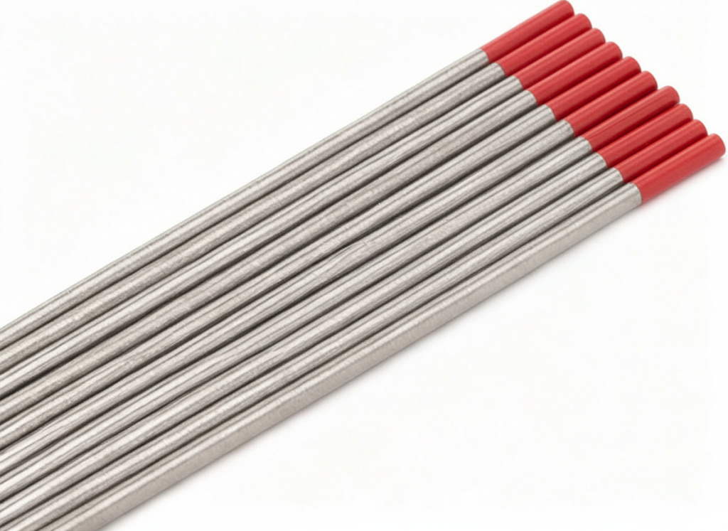
    Replacement cutting rods should be matched to the exact exothermic cutting system, rod diameter, rod length, coating type, and job requirement. The verified Amazon listing below is for Arcair SLICE exothermic cutting rods. Confirm the part number and fitment before ordering.

    No products found.

    Comparison Table

    SymptomLikely CauseCheck FirstDo Not Do
    Rod sparks but will not lightWeak striker contact or weak batteryBattery charge, clamps, striker plateDo not increase oxygen blindly.
    Rod lights then diesLow oxygen flow or blocked passageCylinder, regulator, hose, torchDo not bypass regulator limits.
    Rod burns back toward torchWrong fit, poor seating, or incorrect rodCollet, rod size, torch instructionsDo not keep using a loose rod.
    Cut starts then plugs with slagPoor angle, slow movement, trapped molten metalCutting angle and exit pathDo not stand in the blowback path.
    Heavy smoke and flare-upsCoatings, oil, grease, or contaminated workSurface prep and ventilationDo not cut unknown coatings without controls.

    Related Failure Paths

    Safety Notes

    Exothermic cutting uses oxygen and produces intense heat, sparks, molten metal, slag, smoke, and fire exposure. Follow the cutting system manual, employer procedure, hot-work permit requirements, and site fire-watch rules. Keep combustible materials out of the work area and shield nearby personnel from sparks and molten metal.

    OSHA 1910.253 covers oxygen-fuel gas welding and cutting requirements, including cylinder handling and oxygen equipment precautions. OSHA construction rules in 1926.350 also address gas welding and cutting cylinder handling. ANSI Z49.1 covers safety in welding, cutting, and allied processes, including personnel protection, ventilation, fire prevention, and confined-space precautions.

    Never use oil or grease on oxygen equipment. Never use oxygen as compressed air. Do not cut sealed containers, drums, tanks, or unknown vessels unless they have been properly cleaned, tested, and approved for hot work by a qualified procedure. Use eye and face protection, gloves, flame-resistant clothing, hearing protection, ventilation, and respiratory protection as required by the hazard assessment.

    FAQ

    Why does my exothermic cutting rod spark but not start?

    The most likely causes are weak battery contact, a dirty striker plate, poor clamp connection, low oxygen flow, or a damaged rod end. Check ignition contact and oxygen delivery before replacing the torch.

    Can low oxygen make a slice rod go out?

    Yes. The ignition spark starts the rod, but oxygen sustains the exothermic reaction. Low flow, a blocked passage, a leaking fitting, or an undersized regulator can make the rod die quickly.

    Can oxygen pressure be increased until the rod works?

    No. Use the manufacturer’s published pressure and flow requirements. Increasing oxygen without verifying the system can create unstable cutting, equipment damage, burnback, or a serious fire hazard.

    Do exothermic rods work without electricity?

    Some systems use electrical ignition to start the rod, then oxygen sustains the cut. System details vary by brand and torch design. Verify the exact starting method in the manufacturer’s instructions.

    Are exothermic rods interchangeable between torch brands?

    Not automatically. Rod diameter, length, coating, torch collet, oxygen passage, and safety design must match. Treat cross-brand fitment as Unknown (Verify) unless the manufacturer or supplier confirms compatibility.

    Next Step

    If the rod will not stay lit, start with oxygen supply, hose restrictions, regulator function, striker contact, and rod fitment. Then inspect rod condition and workpiece contamination. If the rod size or coating is uncertain, compare it against the slice rod selection guide before ordering replacement rods or changing the procedure.

    Sources Checked

    • Weld Support Parts Blog: How to Select the Right Slice Rod for Exothermic Cutting.
    • Weld Support Parts Blog: Plasma Cutter Not Cutting Through: Causes and Fixes.
    • Weld Support Parts Blog: Miller HBA-30510 Review & Guide.
    • Weld Support Parts Blog: Welding Fume Extractor Not Pulling Smoke: Causes and Fixes.
    • Weld Support Parts Blog: Cylinder Tank Status Tags Review & Buying Guide.
    • ESAB Arcair brand page: Arcair exothermic cutting and SLICE cutting systems context.
    • Broco Rankin Prime-Cut Cutting Rods product page: rod size families and exothermic cutting context.
    • Airgas Broco 31618/PC-20 listing: Broco rod temperature and cutting-material context.
    • OSHA 1910.253: Oxygen-fuel gas welding and cutting.
    • OSHA 1926.350: Gas welding and cutting.
    • ANSI Z49.1 / AWS safety in welding, cutting, and allied processes reference.
    • Amazon listing checked for ASIN B001HWEFQ0: Slice Exothermic Cutting Rods.
  • Welding Safety Equipment Inspection Checklist for Shop PPE

    Routine PPE inspection helps reduce welding injuries, exposure incidents, arc flash risk, burns, respiratory hazards, and equipment-related downtime. This checklist is designed for fabrication shops, maintenance departments, welding booths, and industrial welding environments where daily PPE verification is required.

    The goal is simple: identify damaged, contaminated, expired, improperly fitted, or non-compliant protective equipment before welding starts.

    Key Takeaways

    • Inspect PPE before every shift and after high-exposure work.
    • Replace cracked lenses, damaged gloves, contaminated respirator filters, and heat-damaged clothing immediately.
    • Verify ANSI, OSHA, AWS, and manufacturer markings where applicable.
    • Do not assume PPE is safe because it “looks usable.”
    • Respirators, helmets, gloves, jackets, and hearing protection all have wear limits.
    • Fit, seal condition, and contamination matter as much as visible damage.

    Problem / Context

    Many welding PPE failures happen gradually. Helmet shells weaken from UV and heat exposure. Respirator seals harden. Gloves absorb oil and solvents. Auto-darkening lenses become unreliable. Grinding debris damages face shields and hearing protection.

    Without a structured inspection process, damaged PPE often stays in service longer than it should.

    Shops performing MIG, TIG, flux-core, stick, plasma cutting, carbon arc gouging, or grinding operations should maintain documented PPE inspection procedures and replacement criteria.

    Daily Welding PPE Inspection Checklist

    PPE ItemInspection CheckCommon Failure SignsAction Required
    Welding HelmetInspect shell, headgear, lens frame, sensors, and controlsCracks, loose headgear, failed auto-darkening response, damaged shellRemove from service if lens response fails or shell is damaged
    Auto-Darkening LensTest switching function before weldingFlickering, delayed darkening, inconsistent shadeReplace batteries, cover lenses, or filter cartridge
    Safety GlassesInspect lenses and side shieldsScratches, cracks, missing side shieldsReplace immediately
    Face ShieldCheck visor clarity and mountingClouding, deep scratches, loose pivotsReplace damaged visor
    RespiratorInspect seal, straps, valves, and filtersSeal deformation, cracked housing, clogged filtersReplace filters or respirator components
    PAPR SystemVerify airflow, battery condition, and filter statusLow airflow alarms, damaged hoses, weak batteryService before use
    Welding GlovesInspect palms, seams, cuffs, and insulationBurn-through, oil saturation, holes, stiff leatherReplace gloves
    Welding JacketInspect sleeves, snaps, and flame-resistant areasBurn holes, contamination, torn cuffsRepair or replace
    FR Sleeves / ApronsCheck stitching and heat damageLoose seams, spark damageReplace if compromised
    Hearing ProtectionInspect ear plugs or earmuffsDirty foam, cracked cushions, loose fitReplace disposable plugs regularly
    Welding BootsCheck soles, metatarsal guards, and lacesHeat damage, exposed toe caps, sole separationRemove from service if protection compromised
    Gas Hose PPE AreaVerify hoses do not contact clothing or hot surfacesBurn marks, abrasion, leaksReplace damaged hoses immediately

    Welding Helmet Inspection Procedure

    • Inspect helmet shell for cracks, warping, or heat damage.
    • Verify headgear tightens correctly and holds position.
    • Check cover lenses for pitting, scratches, and spatter damage.
    • Perform a safe function test on auto-darkening filters before welding.
    • Confirm shade settings match the welding process and amperage.
    • Inspect sensor areas for blockage from dirt or spatter.
    • Verify ANSI Z87.1 markings where applicable.

    Do not use a welding helmet with intermittent darkening performance, cracked filter housings, or damaged retaining frames.

    Respiratory Protection Inspection Steps

    • Inspect face seal for cracking, stiffness, or deformation.
    • Verify straps maintain proper tension.
    • Inspect inhalation and exhalation valves.
    • Check filter expiration and contamination level.
    • Confirm filters match the welding hazard.
    • Perform a seal check before entering the work area.
    • Verify airflow on powered air systems.
    • Inspect hoses and blower connections on PAPRs.

    P100 filters are commonly used for welding particulate, but gas, vapor, stainless steel, galvanized coatings, confined-space work, and chemical exposure may require additional verification.

    For workplace use, respirator selection and maintenance should follow OSHA 1910.134 requirements and the site respiratory protection program.

    Glove and Protective Clothing Inspection

    ItemWhat Usually Wears Out FirstVisual Wear IndicatorsField Fix vs Proper Fix
    MIG GlovesFinger seams and palm areaThin leather, burn-throughTape is not a safe repair — replace gloves
    TIG GlovesFinger sensitivity zonesHeat hardening, seam splitsReplace once dexterity drops
    FR JacketSleeves and front closureBurn holes, oil contaminationRepair minor stitching only if the FR rating is maintained
    Leather SleevesForearm exposure zonesHeat cracking and sparks embedded in leatherReplace if flexibility is lost
    Welding ApronsLower spark zonesBurn-through and torn strapsReplace heavily damaged aprons

    Common Wrong-PPE Mistakes

    • Using grinding face shields without safety glasses underneath.
    • Using expired or overloaded respirator filters.
    • Wearing oil-soaked gloves or jackets near sparks.
    • Using cracked auto-darkening lenses.
    • Ignoring damaged helmet headgear.
    • Using non-FR clothing around sparks or molten metal.
    • Wearing hearing protection incorrectly during grinding operations.
    • Failing to inspect PPE after plasma cutting or carbon arc gouging.

    Compatibility Notes

    Verify helmet lens size, respirator fitment, filter part number, cartridge compatibility, battery type, PAPR airflow rating, and headgear configuration before replacement.

    Compatibility may vary by helmet shell, respirator platform, welding process, and work environment.

    Unknown (Verify) for undocumented aftermarket compatibility claims.

    Related Failure Paths

    • Lens contamination is causing poor visibility and weld defects
    • Respirator seal failure increases fume exposure
    • Burn-through in gloves increases electrical and thermal injury risk
    • Helmet sensor blockage is causing flash exposure
    • Oil-contaminated clothing increases fire risk
    • Damaged hearing protection is contributing to long-term hearing loss
    • Improper boot condition increases slip and crush hazards

    Safety Notes

    • Follow ANSI Z49.1 for welding safety practices.
    • Use ANSI Z87.1-compliant eye and face protection where required.
    • Inspect PPE before every shift.
    • Replace damaged PPE immediately.
    • Maintain respirators according to OSHA respiratory protection requirements.
    • Do not modify PPE outside manufacturer guidance.
    • Do not use damaged FR clothing contaminated with oil or solvents.
    • Always maintain proper ventilation and fume extraction.

    FAQ

    How often should welding PPE be inspected?

    Basic inspection should occur before every shift. More detailed inspections should occur weekly or monthly depending on shop exposure conditions.

    When should respirator filters be replaced?

    Replace filters according to manufacturer schedules, site exposure requirements, or sooner if breathing resistance increases.

    Can cracked welding helmet shells be repaired?

    Generally no. Cracked helmet shells should be removed from service and replaced.

    Do safety glasses still matter under a welding helmet?

    Yes. Many shops require ANSI-rated safety glasses to be worn under welding helmets for additional impact protection.

    What is the most commonly ignored PPE issue in welding shops?

    Respirator fit and filter condition are commonly overlooked, especially in high-fume environments.

    Next Step

    Create a documented PPE inspection log for each welding station, grinding station, and fabrication area. Standardized inspection routines improve consistency, reduce missed hazards, and simplify safety audits.

    Internal Links

    Sources Checked

    • AWS ANSI Z49.1 Safety in Welding, Cutting, and Allied Processes
    • OSHA 1910.132 Personal Protective Equipment
    • OSHA 1910.134 Respiratory Protection
    • NIOSH respirator guidance
    • Manufacturer PPE inspection guidance
    • Weld Support Parts internal safety content
  • Lincoln Magnum PRO 100SG Spool Gun: Aluminum MIG Feed Fix

    Soft aluminum MIG wire is hard to push through a standard MIG gun. It birdnests, shaves, slips at the drive rolls, and burns back into the tip right when the bead should be starting clean. The Lincoln Electric Magnum PRO 100SG spool gun, ASIN B00CP96KJO, is a replacement and upgrade path for welders who already own a compatible Lincoln machine and want more reliable aluminum wire feeding without fighting a long liner path.

    This post focuses on troubleshooting aluminum MIG feed problems, when a spool gun makes sense, what wears first, what to verify before buying, and what spare consumables to keep with the gun.

    Key Takeaways

    • The Lincoln Magnum PRO 100SG is a 4-pin spool gun, product number K3269-1, sold on Amazon under ASIN B00CP96KJO.
    • It is intended to improve feeding of soft aluminum wire by keeping the small wire spool at the gun instead of pushing aluminum through a long MIG gun liner.
    • Verify welder compatibility before buying; 4-pin does not mean universal.
    • The verified kit contents include a 10 ft cable, 0.035 in 4043 aluminum wire, 0.030–0.035 in drive roll, KP2744-035T contact tips, and an electrical harness with toggle switch.
    • Stock extra 0.035 contact tips and aluminum wire because tip wear, wire shaving, and burnback can still happen if setup is wrong.

    The Problem: Aluminum Wire Keeps Birdnesting or Stuttering

    If your aluminum MIG setup keeps birdnesting, the machine may not be the real problem. Aluminum wire is softer than steel wire, so it is easier to deform at the drive rolls and harder to push through a long cable. Once the wire gets scraped, flattened, or restricted, the feed becomes inconsistent and the arc starts popping, surging, or burning back.

    Before replacing a welder, check the wire path. If the problem gets worse when the gun lead is looped, bent, or moved, you are probably dealing with friction, not a voltage setting. For more feed-path diagnosis, see best contact tips for MIG burnback and the MIG porosity fix guide.

    Why a Spool Gun Fixes Many Aluminum Feed Problems

    A spool gun moves the aluminum wire spool to the gun handle. Instead of pushing soft wire from the feeder, through a long liner, and out the contact tip, the gun feeds from a short path near the arc. That shorter path reduces the chance of wire shaving, liner drag, birdnesting, and feed hesitation.

    The Lincoln Magnum PRO 100SG is best viewed as an aluminum MIG feed upgrade for compatible Lincoln compact wire feeder/welders, not as a universal fix for every MIG machine. If your welder is not listed for K3269-1 compatibility, treat fitment as Unknown (Verify).

    Root Causes This Upgrade Helps Address

    • Soft aluminum wire shaving in the feeder.
    • Birdnesting caused by pushing aluminum through a long standard liner.
    • Feed stutter that changes when the gun lead bends.
    • Burnback caused by inconsistent wire delivery at the contact tip.
    • Arc starts that feel erratic even after cleaning the base metal and checking gas flow.

    Root Causes It Will Not Fix

    • Wrong shielding gas for aluminum.
    • Dirty aluminum, oxide contamination, oil, or moisture.
    • Wrong contact tip size.
    • Incorrect spool gun tension or wire brake setup.
    • Unsupported welder compatibility.
    • Poor work clamp connection.
    • Operator technique problems, including excessive stickout or wrong gun angle.

    Product Recommendation

    Best overall upgrade for compatible Lincoln compact MIG machines: Lincoln Electric Magnum PRO 100SG Spool Gun, 4-pin, K3269-1.

    No products found.

    This is the main buy when your goal is to add aluminum MIG capability to a compatible Lincoln setup and reduce the feed problems that happen when soft wire is pushed through a standard MIG gun. It is not the budget choice compared with replacing a contact tip or liner, but it is the more serious upgrade path when aluminum work is recurring.

    What to Verify Before Buying

    • Machine compatibility: Confirm your Lincoln welder supports K3269-1 / 4-pin Magnum PRO 100SG. Do not rely on connector shape alone.
    • Wire diameter: Verified setup information references 0.030–0.035 in aluminum wire capability. Your exact wire choice should match the gun setup and machine chart.
    • Wire alloy: Verified included wire is 0.035 in 4043 aluminum alloy. Other alloys require setup confirmation.
    • Duty cycle: Published seller/spec references list 130 amps at 30% duty cycle. Verify against Lincoln documentation for your exact package and application.
    • Consumables: The verified included contact tip part is KP2744-035T. Keep spares available before starting a project.

    Comparison Table

    OptionBest ForWhat It SolvesLimitations
    Replace contact tip onlyCheap first troubleshooting stepBurnback, spatter-packed tip, poor current transferWill not fix long-path aluminum wire drag
    Replace standard MIG linerSteel MIG feed issues or contaminated linerStutter, drag, wire debris, rough feedStill not ideal for soft aluminum wire on long leads
    Lincoln Magnum PRO 100SGRecurring aluminum MIG work on compatible Lincoln machinesSoft aluminum feeding, birdnesting, wire shaving, feed hesitationCompatibility must be verified; not universal
    Higher-capacity spool gunHeavier aluminum work or higher duty cycle needsMore demanding production useMay require a different welder, connector, or budget

    What Wears Out First

    • Contact tips: Replace when the bore wears, wire starts sticking, or burnback appears.
    • Nozzle area: Clean spatter buildup before it disrupts shielding gas or overheats the tip.
    • Drive roll path: Watch for aluminum shavings, slipping, or wire deformation.
    • Wire spool: Replace contaminated or poorly stored aluminum wire. Aluminum cleanliness matters.
    • Trigger/cable strain points: Inspect if feed cuts in and out when the cable moves.

    Visual Wear Indicators

    • Wire burns back into the contact tip after short starts.
    • Aluminum shavings collect inside the gun or near the wire path.
    • The contact tip opening looks enlarged, oval, dark, or spatter-packed.
    • The wire exits with a scratchy or pulsing feel instead of a steady feed.
    • The bead has inconsistent width because wire speed is not staying stable.

    Common Misdiagnosis

    Many welders chase voltage and wire feed speed first. That can waste time. If the aluminum wire is not feeding smoothly, settings changes only hide the root cause. Confirm wire payoff, tip size, drive roll tension, gas coverage, and base-metal cleanliness before assuming the machine is defective.

    If the weld has holes or black soot, do not blame the spool gun first. Aluminum porosity can come from poor cleaning, wrong gas, leaks, excess stickout, or contaminated filler. See the MIG porosity troubleshooting guide for gas and contamination checks.

    If Ignored

    • Repeated birdnesting wastes aluminum wire and shop time.
    • Burnback can destroy contact tips and stop the weld mid-joint.
    • Wire shaving can contaminate the feed path and create more drag.
    • Inconsistent feed can cause poor fusion, ugly starts, and failed practice coupons or repairs.
    • Operators may over-tighten drive rolls, making soft-wire deformation worse.

    Recommended Shop Setup

    • Lincoln Magnum PRO 100SG spool gun for compatible Lincoln machines.
    • Extra KP2744-035T 0.035 contact tips or verified equivalent.
    • Clean 0.035 in 4043 aluminum wire for general aluminum repair work where appropriate.
    • Dedicated stainless brush for aluminum cleaning.
    • Clean nozzle tools and anti-spatter workflow appropriate for your process.
    • Clear helmet cover lenses so the puddle is visible. If visibility is the issue, read why you can’t see your weld pool and best welding helmet replacement lenses.

    Recommended Spare Quantity

    • Contact tips: Keep at least 5–10 verified 0.035 tips with the spool gun.
    • Aluminum wire: Keep one sealed spare 1 lb spool if aluminum repair work is recurring.
    • Nozzle: Keep one spare if your work creates heavy spatter or the gun travels to jobsites.
    • Cover lenses: Keep a multi-pack near the welder so visibility problems do not get mistaken for technique problems.

    Related Failures

    • Birdnesting at the feeder after switching to aluminum wire.
    • Burnback into the contact tip during starts and stops.
    • Porosity after wire feed becomes inconsistent.
    • Spatter buildup around the nozzle and contact tip.
    • Poor weld pool visibility from scratched helmet lenses.

    FAQ

    Is B00CP96KJO the Lincoln Magnum PRO 100SG spool gun?

    Yes. ASIN B00CP96KJO was verified as the Lincoln Electric Magnum PRO 100SG spool gun, commonly associated with Lincoln product number K3269-1.

    Does the Magnum PRO 100SG fit every Lincoln welder?

    No. It is a 4-pin spool gun for compatible Lincoln machines, but compatibility is not universal. Check your welder manual or Lincoln compatibility table before buying.

    Will a spool gun stop all aluminum porosity?

    No. A spool gun improves wire feeding, but porosity can still come from poor cleaning, oxide, moisture, wrong gas, leaks, drafts, or technique.

    What wire size is the 100SG commonly set up for?

    Verified product information references 0.030–0.035 in wire setup, with included 0.035 in 4043 aluminum wire. Verify your exact wire alloy and diameter against your welder setup chart.

    What consumable should I buy with the spool gun?

    Start with spare 0.035 contact tips that match the Magnum PRO 100SG setup. The verified included tip part is KP2744-035T. Also keep clean aluminum wire and replacement helmet cover lenses on hand.

    Safety Notes

    • Disconnect input power before installing adapters, harnesses, or servicing the gun.
    • Follow the Lincoln manual for installation, setup, and machine compatibility.
    • Wear welding gloves, flame-resistant clothing, and eye/face protection rated for welding.
    • Use proper ventilation when welding aluminum and when running repeated test beads.
    • Do not troubleshoot live electrical connections unless qualified to do so.

    Sources Checked

    • Lincoln Electric Magnum PRO 100SG K3269-1 product page.
    • Lincoln Electric Magnum PRO 100SG product literature PDF.
    • Lincoln Electric POWER MIG 215 MPi literature referencing K3269-1 package inclusion.
    • Lincoln Electric SP-140T literature referencing Magnum PRO 100SG 4-pin accessory details.
    • Amazon product identity check for ASIN B00CP96KJO.
    • Weld Support Parts internal posts on MIG burnback, porosity, wire feed issues, and helmet lens visibility.
  • Why Stainless TIG Welds Sugar on the Back Side

    Stainless TIG sugaring is heavy oxidation on the back side of the weld root. It usually happens when the hot root is exposed to oxygen because the purge is missing, weak, contaminated, or removed too soon. This is a narrower alloy-support follow-up to general TIG weld contamination because stainless root oxidation creates its own inspection, cleanup, and corrosion problems.

    Key Takeaways

    • Sugaring is backside oxidation, not normal heat tint.
    • The most common cause is oxygen reaching the stainless root while it is hot.
    • Back purging with argon is the standard fix for full-penetration stainless TIG welds.
    • Too much purge flow can create turbulence and pull air into the purge zone.
    • Heat input, travel speed, fit-up, purge dams, and purge time all affect root color.
    • For stainless work, welding fume controls matter because chromium and nickel exposure must be considered.

    Problem / Context

    A clean stainless TIG bead on the outside can still fail the job if the inside of the tube, pipe, or sheet joint looks black, crusty, or granular. That rough oxidized root is commonly called sugaring. On sanitary, food-grade, chemical, exhaust, brewery, pharmaceutical, and process piping work, the back side of the weld is often just as important as the cap.

    Sugaring is different from surface soot on the face side. For face-side black soot, start with sooty TIG weld troubleshooting. For pinholes or gas pockets in the bead, use the separate TIG porosity checklist.

    Root Causes

    1. No Back Purge on a Full-Penetration Joint

    When stainless steel reaches welding temperature, the unshielded root side reacts with oxygen. If the joint penetrates through the material and the back side is open to air, oxidation can form even when the torch side looks acceptable.

    2. Purge Gas Starts Too Late

    Starting the purge at the same moment as the arc is usually too late. The enclosed volume must be displaced before welding begins. On tube or pipe, that means allowing enough purge time for the inside atmosphere to be replaced with argon before the root gets hot.

    3. Purge Flow Is Too High or Too Low

    Low flow may not displace air. Excessive flow can stir the purge zone and drag oxygen back into the joint area. Use the procedure, purge equipment instructions, and oxygen monitor where required instead of guessing by sound alone.

    4. Poor Dams, Leaky Tape, or Open Ends

    Purge dams, plugs, foil, tape, and end caps must seal well enough to hold a stable argon blanket while still allowing controlled venting. Completely sealed purge cavities can pressurize and disturb the puddle; wide-open cavities waste gas and leave oxygen in the root area.

    5. Excessive Heat Input

    High amperage, slow travel, repeated reheating, or a wide root opening can keep the back side hot long enough to oxidize. Heat control is especially important on thin 304 and 316 stainless tube. If the torch side is also discolored or contaminated, review TIG contamination causes before blaming filler metal.

    6. Torch Shielding Is Being Confused With Back Purging

    A larger TIG cup or gas lens improves face-side shielding, but it does not protect the root side of a closed tube or pipe. Use the correct TIG cup size for the torch side, then treat root purge as a separate gas-coverage problem.

    Solution

    Step 1: Confirm the Joint Actually Needs a Purge

    Full-penetration stainless joints, tube welds, pipe roots, sanitary welds, process piping, and corrosion-critical welds normally need root shielding. Cosmetic stainless sheet welds with no backside exposure may have different acceptance requirements. Verify the job specification, weld procedure, customer requirement, or code before deciding that sugaring is acceptable.

    Step 2: Set Up a Controlled Argon Path

    Introduce argon at one end of the purge zone and vent from the opposite side or high point. The goal is not pressure; the goal is oxygen displacement. Avoid blasting argon straight at the root opening. Diffuse the flow when possible and keep the vent large enough to prevent pressure buildup.

    Step 3: Use Proper Purge Dams or Plugs

    For small tube and exhaust work, silicone purge plugs can make setup more repeatable than loose tape. For pipe, soluble purge paper or dedicated purge dams may be better. Always verify temperature limits, pipe size, chemical compatibility, and cleanup requirements before choosing a dam or plug.

    Step 4: Let the Purge Stabilize Before Welding

    Do not strike the arc immediately after opening the purge valve. Give the purge enough time to displace air from the enclosed area. Critical stainless work may require an oxygen monitor instead of a time estimate.

    Step 5: Keep the Purge Running After the Arc Stops

    The root can still oxidize after the arc ends if the purge is shut off while the weld is hot. Leave the purge on long enough for the root to cool below the point where heavy oxidation forms. The exact time depends on material thickness, heat input, joint design, and procedure requirements.

    Step 6: Reduce Heat Input Before Increasing Gas

    If the root still sugars with a stable purge, check amperage, travel speed, fit-up, root opening, pulse settings, and filler addition. More gas is not always the fix. Excessive purge or torch flow can make shielding worse by creating turbulence.

    Specs / Verification Notes

    Item to VerifyWhy It MattersField Note
    Base alloy304, 304L, 316, 316L, duplex, and nickel alloys may have different procedure requirements.Unknown (Verify)
    Filler metalWrong filler can reduce corrosion performance or fail job requirements.Match WPS or engineered requirement.
    Purge gasArgon is commonly used for stainless TIG back purging.Verify purity and cylinder labeling.
    Purge oxygen levelCritical stainless roots may require measured oxygen levels.Unknown (Verify by procedure).
    Purge dam ratingHeat and material compatibility vary by plug, dam, or paper.Verify manufacturer limits.
    Acceptance criteriaSome work rejects any heavy root oxidation; other work may not.Verify code, customer spec, or WPS.

    Product Section

    For small stainless tube, exhaust, and fabrication work, reusable silicone purge plugs can help create a more controlled argon cavity than improvised tape alone. Confirm the plug size range, temperature rating, venting method, and job requirements before use.

    No products found.

    Comparison Table

    MethodBest UseMain RiskVerification Point
    Silicone purge plugsTube, exhaust, small pipe, repeat shop setupsWrong size or overheatingVerify size and temperature rating.
    Soluble purge paperPipe where the dam must dissolve after weldingPoor seal or moisture sensitivityVerify pipe size and cleanup requirements.
    Foil and tape damTemporary sheet or odd-shape purge boxesLeaks, adhesive failure, trapped pressureInspect vents and seals before welding.
    Copper or aluminum backingFlat sheet or open backside accessMay not replace purge on corrosion-critical workVerify procedure acceptance.
    No purgeOnly when the procedure allows itRoot sugaring and corrosion concernsConfirm with WPS or customer requirement.

    Related Failure Paths

    Safety Notes

    Stainless welding can involve chromium and nickel in welding fumes. OSHA identifies occupational exposure to hexavalent chromium as possible through inhalation of dusts, mists, or fumes containing chromium compounds, and OSHA chromium standards require assessment of potential employee exposure. Use local exhaust, ventilation, respiratory protection when required, eye protection, gloves, and the employer’s written safety procedures.

    Argon purge gas can displace oxygen in confined or poorly ventilated spaces. Never purge inside enclosed spaces without a confined-space plan, atmospheric monitoring where required, and proper supervision. ANSI Z49.1 and AWS safety materials should be used alongside site-specific procedures.

    FAQ

    Is stainless sugaring the same as porosity?

    No. Sugaring is heavy oxidation on the back side of the stainless root. Porosity is trapped gas inside the weld bead. Both can involve shielding problems, but they are different failures.

    Can a larger TIG cup stop backside sugaring?

    Not by itself. A larger cup or gas lens helps shield the torch side. Backside sugaring requires root-side shielding, usually by back purging or an approved backing method.

    Should the purge be turned off as soon as the weld is finished?

    No. Keep the purge running while the root cools. Turning it off too early can oxidize the hot stainless root after the arc stops.

    Can sugaring be brushed away?

    Light surface color and heavy root oxidation are not the same issue. Heavy sugaring may require mechanical removal, repair, or rejection depending on the job specification. Do not assume brushing makes the weld acceptable.

    Does every stainless weld need a purge?

    No. The need depends on penetration, backside exposure, alloy, service environment, inspection requirement, and WPS. Full-penetration stainless tube and pipe are common cases where purging is expected.

    Next Step

    If the stainless root is black or crusty, do not start by increasing amperage or adding filler. First confirm purge coverage, purge time, venting, and oxygen control. Then check heat input, fit-up, and torch-side shielding. For face-side contamination, use the TIG contamination troubleshooting guide before replacing consumables.

    Sources Checked

    • Miller Welds: How to Solve 10 Common TIG Welding Problems; stainless sugaring/backside oxidation and argon back purge guidance.
    • Miller Welds: Pipe Contractor Eliminates Back Purge on Stainless Steel Pipe Welds; shielding gas displacement and oxidation prevention context.
    • OSHA: Hexavalent Chromium Exposure and Controls; chromium exposure assessment and standards overview.
    • OSHA Publication 3373: Hexavalent Chromium; chrome alloys, stainless steel, and welding-related chromium context.
    • AWS Safety and Health Fact Sheet: welding fume exposure assessment, including chromium and nickel focus for stainless welders.
    • Weld Support Parts Blog: TIG contamination, TIG porosity, sooty TIG welds, and TIG cup size support articles.
    • Amazon listing checked for ASIN B07VMZ646H: Strictly Modified High Temperature Silicone Welding Back Purging Plugs 2 inch to 2-1/4 inch.
  • 3M Speedglas G5-02 Welding Helmet Support Guide: Fitment, Lens Protection, and Ordering Checks

    The 3M Speedglas G5-02, Auto Darkening Welding Helmet, Pack of (1)

    “>3M Speedglas G5-02 Auto Darkening Welding Helmet is a professional welding helmet built around the Speedglas G5-02 platform. This support article is intended to help buyers confirm the correct helmet, understand the verified specs, and avoid ordering the wrong lens protection or replacement accessory.

    Key Takeaways

    • Primary product: 3M Speedglas G5-02 Auto Darkening Welding Helmet, Pack of 1.
    • Arc Weld SKU: 08-0100-50IC.
    • Verified shade range from the Arc Weld product page: variable dark shade 8 to 12.
    • 3M identifies the G5-02 as a welding helmet using Curved Glass Technology for a viewing filter that follows the curved shape of the head.
    • For replacement protection plates, confirm G5-02 compatibility before ordering.

    Product Overview

    The 3M Speedglas G5-02 is an auto-darkening welding helmet listed by Arc Weld Store under SKU 08-0100-50IC. The product page identifies the brand as 3M and describes the helmet with Natural Color Technology, adjustable arc detection sensitivity, a delay function, and Bluetooth connectivity through the 3M Connected Equipment App.

    For commercial buyers, the important ordering point is simple: this is a complete G5-02 helmet listing, not a cover plate, not a replacement ADF, and not a generic welding hood. Confirm that your shop needs the helmet assembly before purchasing.

    View this product at Arc Weld Store: 3M Speedglas G5-02, Auto Darkening Welding Helmet, Pack of (1)

    “>3M Speedglas G5-02 Auto Darkening Welding Helmet

    Best For

    • Professional welding operations that need a premium auto-darkening welding helmet.
    • Welders who want a G5-02 helmet platform with curved filter design.
    • Shops standardizing on 3M Speedglas welding helmet equipment.
    • Buyers replacing a complete welding helmet rather than only a cover plate or lens accessory.

    Key Specs

    Product3M Speedglas G5-02 Auto Darkening Welding Helmet, Pack of 1
    Brand3M
    Arc Weld SKU08-0100-50IC
    Helmet SeriesSpeedglas G5-02
    Auto-DarkeningYes
    Dark Shade Range8 to 12
    Natural Color TechnologyListed by Arc Weld Store
    Adjustable Arc Detection SensitivityListed by Arc Weld Store
    Delay FunctionListed by Arc Weld Store
    Bluetooth ConnectivityListed by Arc Weld Store
    Included ItemsUnknown (Verify)
    CertificationsUnknown (Verify)
    Viewing AreaUnknown (Verify)
    Battery TypeUnknown (Verify)
    WeightUnknown (Verify)

    Compatibility / Fitment Notes

    The product page identifies this helmet as the 3M Speedglas G5-02. For replacement parts, do not assume that other Speedglas series accessories will fit. G5-01, G5-03, 9100, and 9002NC components may use different filter, cover lens, or shell designs. Confirm the helmet series and part number before ordering replacement plates, ADF components, headgear, or accessories.

    3M lists a G5-02 curved auto-darkening filter under alternative ID 08-0000-50iC, but the Arc Weld product URL supplied for this article is the helmet listing with SKU 08-0100-50IC. If you need only the filter, verify the exact replacement filter part number before purchasing.

    Before You Order

    • Confirm you need the complete 3M Speedglas G5-02 helmet, not only a replacement lens or cover plate.
    • Verify the helmet series: G5-02.
    • Confirm the Arc Weld SKU: 08-0100-50IC.
    • Confirm whether shade range 8 to 12 supports your welding process and amperage range.
    • Check whether your shop requires documented ANSI, OSHA, or site-specific PPE compliance before ordering. Certifications on this Arc Weld listing: Unknown (Verify).
    • Confirm whether any additional outside protection plates are needed for daily production use.
    • Confirm whether your application requires respiratory protection. This listing is for a welding helmet; respirator compatibility: Unknown (Verify).
    • Confirm whether your crew needs spare batteries, cover plates, sweatbands, headgear, or storage protection. Included spare parts: Unknown (Verify).
    • Confirm whether Bluetooth/app features are allowed under your jobsite device policies.
    • For replacement components, match the OEM part number before ordering.

    Accessories / Compatible Products

    Technically relevant accessories should be selected by confirmed helmet series and part number. The most direct Arc Weld accessory found for this product family is the G5-02 outside protection plate.

    Related ItemUse CaseCompatibility Note
    3M Speedglas G5-02 Outside Protection Plate 08-0200-52, Scratch Resistant, 5 ea/Case “>3M Speedglas G5-02 Outside Protection Plate 08-0200-52, Scratch Resistant, 5 ea/CaseReplacement outside protection plates for the G5-02 helmet family.Listed by Arc Weld as designed specifically for the 3M Speedglas G5-02 welding helmet.
    3M Speedglas G5-03 Pro Welding Helmet 10-0100-30TW with G5TW ADF with Grind Mode, TAP, Natural Color, Tack Weld Mode “>3M Speedglas G5-03 Pro Welding Helmet 10-0100-30TWCompare another Speedglas helmet option.Not a replacement part for the G5-02. Compatibility: Unknown (Verify).
    Inside and Outside Cover Lens CollectionFind cover lenses and protection plates.Filter by exact helmet model and part number before ordering.
    Welding Helmet CollectionCompare welding helmet options.Compare by process, shade range, viewing area, and safety requirements.

    Common Applications

    • Precision welding where optical clarity and puddle visibility are important.
    • Professional fabrication and maintenance welding.
    • Shop environments where helmet standardization reduces setup confusion.
    • Applications where replacement cover plates should be stocked to protect the auto-darkening filter.

    Shipping / Returns Notes

    Arc Weld Store lists this product as typically shipping within 1–2 business days, shipping from Corydon, Indiana, with free ground shipping to the lower 48 on qualifying orders. Returns are listed as accepted on unused items in original packaging. Always check the live product page before ordering because shipping, pricing, and availability can change.

    FAQ

    Is this a complete welding helmet or a replacement lens?

    The Arc Weld listing is for the 3M Speedglas G5-02 Auto Darkening Welding Helmet, Pack of 1. Replacement lens and cover plate requirements should be verified separately by part number.

    What is the Arc Weld SKU?

    The Arc Weld SKU shown on the product page is 08-0100-50IC.

    What shade range is listed?

    The Arc Weld product page lists a variable dark shade range of 8 to 12.

    Which outside protection plate was found for the G5-02?

    Arc Weld lists the 3M Speedglas G5-02 Outside Protection Plate 08-0200-52, Scratch Resistant, 5 ea/Case as designed specifically for the 3M Speedglas G5-02 welding helmet.

    Can G5-03 parts be used on the G5-02?

    Compatibility: Unknown (Verify). Do not substitute G5-03 parts for G5-02 parts unless the manufacturer or Arc Weld confirms the fitment.

    Safety Notes

    Welding helmets and filter lenses must be selected for the welding process, amperage, radiant energy exposure, impact hazards, and workplace safety requirements. OSHA welding guidance references filter lens requirements and appropriate eye and face protection. Confirm jobsite PPE requirements before use, and wear approved safety glasses or goggles under the helmet when required by your safety program.

    Sources Checked

    • Arc Weld Store product page for 3M Speedglas G5-02 Auto Darkening Welding Helmet, SKU 08-0100-50IC.
    • Arc Weld Store product page for 3M Speedglas G5-02 Outside Protection Plate 08-0200-52.
    • Arc Weld Store welding helmet and cover lens collections.
    • 3M Speedglas product information for G5-02 and G5-02 curved auto-darkening filter references.
    • OSHA welding eye and face protection guidance.
    • CDC/NIOSH PPE-Info reference for ANSI/ISEA Z87.1-2020 scope.

    End CTA: 3M Speedglas G5-02, Auto Darkening Welding Helmet, Pack of (1)

“>Check current stock at Arc Weld Store

  • Lincoln Electric Square Wave® 205 TIG Welder K5613-1: Fitment, Specs, and Ordering Guide

    The Lincoln Electric Square Wave® 205 TIG Welder K5613-1 is a dual-voltage AC/DC TIG and AC/DC Stick welding power source built for aluminum TIG work, steel and stainless TIG work, and Stick welding applications where portability matters. This guide helps buyers verify the machine, included components, input power, torch family, consumables, and accessory needs before ordering from Arc Weld Store.

    View this product at Arc Weld Store

    Key Takeaways

    • Model: Lincoln Electric Square Wave® 205 TIG Welder
    • SKU / product number: K5613-1
    • Processes: AC/DC TIG and AC/DC Stick
    • Input power: 120V or 230V, single phase, 60 Hz
    • Best fit: aluminum TIG, steel TIG, stainless TIG, Stick welding, light fabrication, education, motorsports, and shop repair
    • Included torch family: Caliber® 17 TIG Torch Ready-Pak®; verify all front-end consumables before reordering
    • Do not assume consumable compatibility by welder model alone; confirm torch series, tungsten size, cup style, and gas lens setup before ordering accessories

    Product Overview

    The Lincoln Electric Square Wave® 205 K5613-1 is a compact AC/DC TIG and Stick welder for buyers who need TIG control for aluminum and DC TIG performance for steel or stainless. Lincoln lists the machine with pulse, AC frequency, and AC balance controls, plus a 4.3 in. LCD display for setup and parameter changes.

    Arc Weld Store lists this item as the Lincoln Electric Square Wave® 205 TIG Welder K5613-1. Because the original product handle contains a special trademark character, this article uses a clean Arc Weld Store SKU-search link for K5613-1 to avoid broken blog links.

    Upper-middle CTA: Check current stock at Arc Weld Store

    Best For

    • AC TIG welding on aluminum
    • DC TIG welding on steel and stainless steel
    • Light fabrication and repair work
    • Motorsports, maker, education, and small-shop welding stations
    • Buyers who want TIG and Stick capability from one portable machine
    • Work areas where 120V convenience and 230V maximum output capability are useful

    Key Specs

    Product nameLincoln Electric Square Wave® 205 TIG Welder
    SKU / product numberK5613-1
    BrandLincoln Electric
    ProcessesAC/DC TIG, AC/DC Stick
    Input power120/1/60 or 230/1/60
    120V TIG rated output125A/25%; 100A/60%; 85A/100%
    120V DC Stick rated output80A/25%; 70A/60%; 65A/100%
    120V AC Stick rated output70A/100%
    120V TIG output range8–125A
    120V DC Stick output range15–90A
    120V AC Stick output range15–70A
    230V TIG rated output205A/25%; 160A/60%; 130A/100%
    230V DC Stick rated output170A/25%; 130A/60%; 100A/100%
    230V AC Stick rated output140A/25%; 115A/60%; 100A/100%
    230V TIG output range8–205A
    230V DC Stick output range15–170A
    230V AC Stick output range15–140A
    Dimensions14.75 x 9.27 x 21 in. / 375 x 235 x 534 mm
    Net weight36 lb / 16.33 kg
    Display4.3 in. LCD display
    Ingress ratingIP21S
    PriceVerify current price at Arc Weld Store
    Stock statusUnknown (Verify)

    Compatibility / Fitment Notes

    This is a complete welder package, not a replacement board, torch-only item, or consumable kit. The main fitment questions are input power, process requirement, torch family, remote connector needs, cable length, and consumable selection.

    • Machine fit: Verify that K5613-1 is the correct Lincoln Electric Square Wave® 205 package before ordering.
    • Power fit: Confirm your available input power is 120V or 230V single phase, 60 Hz.
    • Maximum output: Use 230V input when maximum TIG and Stick output is required.
    • Torch fit: The package includes a Caliber® 17 TIG Torch Ready-Pak®. Consumables should be selected for the actual torch series and setup, not only by welder model.
    • Remote fit: The included Foot Amptrol is K870. Verify replacement remote controls by Lincoln part number and connector style.
    • Gas fit: TIG shielding gas and cylinder connection requirements must be verified for the application. Shielding gas is not confirmed as included.
    • Stick fit: Confirm electrode type, amperage demand, and AC/DC Stick requirements before assuming the machine is the right fit for production work.

    Before You Order

    Use this checklist to reduce wrong-machine, wrong-consumable, and wrong-accessory orders.

    • Confirm the product number: K5613-1.
    • Confirm your available input voltage: 120V or 230V.
    • Confirm whether your work requires AC TIG, DC TIG, AC Stick, DC Stick, or multiple processes.
    • Confirm duty cycle needs against your weld schedule.
    • Confirm maximum required amperage for TIG and Stick work.
    • Confirm the included torch series before buying cups, collets, gas lenses, or tungsten.
    • Confirm tungsten diameter and tungsten type for your weld procedure.
    • Confirm shielding gas requirements for the base metal and process.
    • Confirm whether a foot control or hand control is preferred for the work area.
    • Confirm cable length requirements for the welding station.
    • Confirm whether additional PPE, work clamp setup, welding table, cart, or cylinder handling equipment is needed.
    • Confirm any replacement accessory by OEM number before ordering.

    Accessories / Compatible Products

    The Square Wave® 205 package includes core TIG and Stick setup components, but most users should still plan for consumables, tungsten, PPE, and gas handling items. Compatibility must be verified by torch series, tungsten size, cup style, connector style, and application.

    Accessory groupWhy it mattersCompatibility note
    TIG consumablesCups, collets, collet bodies, gas lenses, and front-end parts are wear items.Compatibility: Verify against Caliber® 17 / 17-18-26 family and tungsten size.
    TungstenRequired for TIG welding; size and type depend on amperage and material.Compatibility: Unknown (Verify)
    TIG torchesUseful if replacing the included torch or changing torch size.Compatibility: Verify torch series, amperage rating, connector, and cable length.
    Gas regulationNeeded for shielding gas delivery and flow control.Compatibility: Verify gas type, cylinder connection, and flow range.
    PPEHelmet, gloves, jacket, sleeves, and eye protection support safer welding operations.Compatibility: Select by process, heat exposure, and shop requirements.

    Related Arc Weld Store links:

    Common Applications

    • AC TIG welding on aluminum
    • DC TIG welding on steel
    • DC TIG welding on stainless steel
    • Stick welding for repair and outdoor work
    • Light fabrication and maintenance welding
    • Motorsports fabrication
    • Education and training labs
    • Maker and small-shop welding stations

    Shipping / Returns Notes

    Arc Weld Store lists this product as shipping from Corydon, Indiana. Verify current stock, lead time, shipping eligibility, pickup availability, and return requirements before opening or installing the product. Returns should be confirmed before use because welding machines and accessories may need to remain unused and in original packaging to qualify.

    FAQ

    Is the Lincoln Square Wave® 205 K5613-1 for TIG only?

    No. Lincoln lists the Square Wave® 205 for AC/DC TIG and AC/DC Stick welding.

    Can this welder run on both 120V and 230V?

    Yes. Lincoln lists input power as 120/1/60 and 230/1/60. Use 230V input when the higher output range is required.

    What torch is included with K5613-1?

    Lincoln lists the included TIG torch as the Caliber® 17 TIG Torch Ready-Pak® – 12 ft. K5339-17F-1. Verify the actual torch and consumable family before ordering spare front-end parts.

    Are TIG consumables included?

    Lincoln lists a Caliber 17/18/26 Series Medium Duty TIG Torch Parts Kit KP4760-MD as included. Verify the contents and required tungsten sizes before placing a consumable order.

    Does this package include shielding gas?

    Shielding gas is not verified as included. Confirm gas cylinder, gas type, and regulator requirements before welding.

    Why does this article use a search link instead of the original product handle?

    The original product URL contains a special trademark character in the handle. The SKU-search link avoids that character and helps prevent broken blog links while still directing buyers to the K5613-1 product result at Arc Weld Store.

    What should I verify before buying replacement parts?

    Verify the machine model, OEM part number, torch series, connector style, cable length, tungsten size, cup style, gas lens setup, and process requirements before ordering.

    Safety Notes

    Follow the Lincoln Electric operator manual and all workplace welding safety requirements before installation or use. Confirm electrical input, grounding, shielding gas handling, PPE, ventilation, hot-work controls, and fire-watch requirements for the work area. Welding equipment should be installed and operated only by trained personnel.

    Sources Checked

    • Arc Weld Store product page for Lincoln Electric Square Wave® 205 TIG Welder K5613-1
    • Lincoln Electric Square Wave® 205 product information
    • Lincoln Electric Square Wave® 205 specification sheet, publication E3.220, issue date 05/25

    End CTA: View the Lincoln Electric Square Wave® 205 TIG Welder K5613-1 at Arc Weld Store

  • How to Stop MIG Nozzle Spatter from Blocking Gas Coverage

    MIG weld porosity is often blamed on shielding gas settings, but a blocked nozzle can cause the same problem. When spatter builds up inside the MIG gun nozzle, shielding gas flow can become restricted, uneven, or turbulent. The result may be pinholes, black soot, erratic arc behavior, and poor bead appearance.

    This guide explains how nozzle spatter buildup causes gas coverage problems, what to check first, and how to clean and prevent buildup without damaging the gun consumables.

    Key Takeaways

    • Spatter inside the MIG nozzle can restrict shielding gas and cause porosity.
    • A nozzle that looks acceptable from the outside may be blocked internally.
    • Nozzle gel can reduce spatter adhesion, but it should not be over-applied.
    • Contact tip, diffuser, and nozzle condition should be checked together.
    • Porosity troubleshooting should include gas leaks, flow rate, wind, base metal cleanliness, and consumable buildup.

    Problem / Context

    A MIG nozzle collects spatter during normal welding. If the buildup is not removed, it can narrow the gas path around the contact tip and diffuser. Shielding gas may still be flowing at the regulator, but the gas envelope at the weld puddle may be weak or uneven.

    This issue is common when welding with short-circuit transfer, welding in tight corners, using excessive wire stickout, welding on dirty material, or running settings that create heavy spatter. It can also happen when the nozzle is dipped too deeply into anti-spatter compound.

    Root Causes

    • Internal nozzle buildup: Spatter collects inside the nozzle and blocks the gas path.
    • Dirty diffuser: Spatter or debris around diffuser holes disrupts gas flow.
    • Damaged contact tip: A worn or oversized tip can cause unstable wire feeding and more spatter.
    • Excessive nozzle gel: Too much compound can contaminate the nozzle, contact tip, or weld area.
    • Incorrect settings: Voltage, wire speed, stickout, and travel angle can all affect spatter level.
    • External gas problems: Wind, leaks, low cylinder pressure, incorrect gas mix, or poor flow rate can also cause porosity.

    Solution

    Remove the nozzle and inspect the inside, not just the outside edge. If spatter is narrowing the opening or covering diffuser holes, clean the nozzle before adjusting the machine. Use proper MIG pliers or a nozzle cleaning tool rather than striking the nozzle against the workbench.

    • Turn off the welder before removing or servicing gun consumables.
    • Remove the nozzle and clear spatter from the inside wall.
    • Inspect the contact tip for wear, burnback, keyholing, or blocked wire passage.
    • Check the diffuser or gas ports for spatter blockage.
    • Reinstall consumables securely without cross-threading.
    • Apply nozzle gel lightly if used, keeping it away from the contact tip bore and weld joint.
    • Run a short test weld and inspect for porosity before continuing production work.

    Specs / Verification Notes

    Item to VerifyWhat to CheckNotes
    MIG gun modelNozzle, tip, and diffuser compatibilityUnknown (Verify)
    Wire sizeContact tip size matches wire diameterUnknown (Verify)
    Shielding gasCorrect gas or gas mix for processUnknown (Verify)
    Gas flowFlow at the gun, not only at the regulatorUnknown (Verify)
    Nozzle conditionInternal spatter, deformation, loose fitReplace if damaged
    Diffuser conditionBlocked gas holes or damaged threadsReplace if damaged

    Product Section

    Nozzle gel can help reduce weld spatter adhesion inside a MIG nozzle. It should be used as a support item, not as a substitute for correct settings, clean consumables, and proper shielding gas coverage. Verify current product size, seller, and safety information before purchase.

    No products found.

    Comparison Table

    ApproachBest UseRisk
    Routine nozzle cleaningDaily MIG gun maintenanceMay be skipped when production is rushed
    Nozzle gelReducing spatter adhesionOver-application can create contamination risk
    Replacing nozzleDamaged, distorted, or heavily packed nozzleWrong nozzle can affect gas coverage
    Changing weld settingsReducing excessive spatter at the sourceIncorrect changes can create new weld defects

    Safety Notes

    • Allow the nozzle and contact tip to cool before handling. MIG gun front-end parts can remain hot after welding.
    • Use safety glasses when removing spatter because fragments can break loose during cleaning.
    • Follow the product SDS for nozzle gel or anti-spatter compound handling and storage.
    • Keep anti-spatter compounds away from open flames unless the product documentation confirms safe use conditions.
    • Follow OSHA welding, cutting, and brazing requirements and ANSI Z49.1 safety guidance for welding, cutting, and allied processes.

    FAQ

    Can nozzle spatter cause MIG porosity?

    Yes. Heavy spatter buildup inside the nozzle can interfere with shielding gas coverage and contribute to porosity.

    How often should a MIG nozzle be cleaned?

    Clean it whenever spatter buildup is visible inside the nozzle or when weld quality changes. High-spatter applications may require frequent cleaning during the job.

    Can too much nozzle gel cause problems?

    Yes. Excessive gel can collect debris or contaminate the contact tip and work area. Use a light amount and keep it out of the wire path.

    Should the contact tip be replaced when cleaning the nozzle?

    Inspect it at the same time. Replace the contact tip if it is worn, blocked, burned back, loose, or no longer feeding wire consistently.

    What should be checked if the nozzle is clean but porosity remains?

    Check gas flow at the gun, gas leaks, wind, base metal contamination, wire condition, polarity, and the correct gas type for the wire and process.

    Next Step

    If MIG porosity appears suddenly, remove the nozzle and inspect the gas path before changing the welder settings. Clean the nozzle, check the diffuser and contact tip, verify gas flow, then make a short test weld on clean material.

    Sources Checked

    • Amazon product page for Forney Nozzle Gel 16 Oz, ASIN B00IOX4GBE
    • OSHA 1910.252 welding, cutting, and brazing general requirements
    • OSHA Eye Protection against Radiant Energy during Welding and Cutting fact sheet
    • AWS Eye and Face Protection for Welding and Cutting Operations fact sheet
    • ANSI Z49.1 safety guidance for welding, cutting, and allied processes
  • How to Fix an Unstable TIG Arc from Poor Tungsten Prep

    A wandering TIG arc is often blamed on gas flow, amperage, or the machine. Those issues can matter, but the tungsten electrode is one of the first places to check. A contaminated, poorly ground, or incorrectly shaped tungsten can make the arc drift, split, sputter, or pull away from the joint.

    This guide covers how to identify tungsten-prep problems, what usually causes them, and what to verify before replacing torch parts or changing machine settings.

    Key Takeaways

    • A TIG arc that wanders, flickers, or splits can often be traced to tungsten contamination or poor grind direction.
    • Grinding marks should run lengthwise with the tungsten, not around it.
    • A dipped tungsten should be cut back or re-ground before welding continues.
    • Use a dedicated tungsten grinder or wheel to reduce cross-contamination from steel, aluminum, or abrasive debris.
    • Verify torch setup, gas coverage, and electrode size before assuming the welder is the problem.

    Problem / Context

    An unstable TIG arc can show up as arc wander, inconsistent starting, dirty weld edges, excessive tungsten balling, black peppering near the weld, or a weld puddle that does not stay centered under the electrode.

    These symptoms are common after the tungsten touches the weld puddle, filler rod, work clamp area, or a contaminated bench grinder. The issue may also appear after switching from aluminum to stainless or carbon steel without cleaning the electrode properly.

    Root Causes

    • Contaminated tip: The tungsten touched the puddle, filler wire, base metal, or dirty work surface.
    • Wrong grind direction: Circular grinding marks can encourage the arc to wander around the tip.
    • Shared grinding wheel: A wheel used for steel or aluminum can embed unwanted material into the electrode.
    • Overheated tungsten: Excessive amperage, poor torch cooling, or too small an electrode can damage the tip.
    • Incorrect stickout: Long stickout without enough gas coverage can oxidize the tungsten and destabilize the arc.
    • Loose torch parts: A loose collet, damaged collet body, or poor gas lens seating can create inconsistent current transfer or shielding.

    Solution

    Start by removing any contaminated portion of the tungsten. Do not simply grind over a dipped tip if filler metal or base metal has fused into it. Cut back the contaminated section, then re-grind the electrode.

    • Use a dedicated tungsten grinder or a wheel reserved only for tungsten.
    • Grind lengthwise so the grind lines run from the body of the tungsten toward the point.
    • Keep the electrode centered while grinding to avoid an off-center point.
    • Use a consistent included angle for the job instead of changing tip shape randomly between welds.
    • For DC TIG on steel or stainless, use a pointed or slightly truncated point as required by the procedure.
    • For AC aluminum, follow the machine and tungsten manufacturer guidance for electrode type and tip preparation.

    Specs / Verification Notes

    Item to VerifyWhat to CheckNotes
    Tungsten typeConfirm electrode material and color codeUnknown (Verify)
    Tungsten diameterMatch electrode size to amperage rangeUnknown (Verify)
    Grind directionLengthwise grind marksAvoid circular grind marks
    Grinding wheelDedicated tungsten wheel or sharpenerDo not share with general metal grinding
    Torch partsCollet, collet body, cup, gas lens, back capReplace damaged consumables
    Shielding gasCorrect gas, flow rate, hose condition, leaksUnknown (Verify)

    Product Section

    A tungsten sharpener can help keep grind angle and grind direction more consistent than freehand grinding on a shared bench wheel. Verify compatibility with the rotary tool, tungsten diameters, and wheel size before purchasing.

    No products found.

    Comparison Table

    MethodBest UseRisk
    Dedicated tungsten sharpenerRepeatable tungsten prepMust verify tool compatibility
    Dedicated bench wheelShop setup with controlled workflowEasy to contaminate if others use it
    Shared grinderEmergency field use onlyHigh contamination risk
    Hand fileMinor cleanup onlySlow and inconsistent for full prep

    Safety Notes

    • Use eye and face protection suitable for grinding and welding. OSHA notes that welding and cutting can expose workers to radiant energy that can injure the eyes.
    • Use the correct welding lens shade for the TIG amperage and work conditions.
    • Control grinding dust, especially when preparing thoriated tungsten. Follow shop safety procedures and applicable SDS guidance.
    • Do not grind tungsten near open containers, flammables, or clean assembly areas where dust contamination is a concern.
    • Follow ANSI Z49.1 safety guidance for welding, cutting, and allied processes where applicable.

    FAQ

    Can a dirty tungsten really make the arc wander?

    Yes. Contamination on the electrode tip can change how the arc starts and where it anchors. A dipped tungsten should be corrected before continuing the weld.

    Should tungsten be ground in a circle or lengthwise?

    Lengthwise grinding is preferred for TIG electrode preparation. The grind marks should run along the tungsten, not around it.

    Can one grinder wheel be used for tungsten and steel?

    It is not recommended. A shared grinding wheel can transfer contaminants into the tungsten and create arc stability problems.

    Why does the tungsten keep balling up on DC TIG?

    Possible causes include wrong polarity, excessive amperage for the electrode size, poor tip prep, contaminated tungsten, or incorrect tungsten type. Verify machine polarity and electrode size first.

    Does a gas lens fix tungsten contamination?

    No. A gas lens can improve shielding coverage in the right setup, but it will not fix a contaminated or poorly ground tungsten.

    Next Step

    If the TIG arc is unstable, remove and inspect the tungsten before changing machine settings. Cut back contamination, re-grind lengthwise on a dedicated wheel or sharpener, then verify torch parts and gas coverage before restarting the weld.

    Sources Checked

    • Amazon product page for 3mirrors Aluminum Tungsten Electrode Sharpener Grinder Head, ASIN B09F9J7GSV
    • OSHA Eye Protection against Radiant Energy during Welding and Cutting fact sheet
    • OSHA Welding, Cutting, and Brazing standards overview
    • AWS welding lens shade safety guidance
    • Diamond Ground Products tungsten electrode guidebook
  • Why MIG Wire Burns Back Into the Contact Tip

    MIG burnback happens when the welding wire melts into the contact tip instead of feeding cleanly into the weld puddle. It is a common shop problem because the symptom looks simple, but the cause can come from wire speed, stickout, liner drag, contact tip wear, drive roll setup, or grounding.

    This guide focuses on practical troubleshooting for short-circuit MIG welding where the wire repeatedly fuses to the contact tip, stalls at the gun, or creates inconsistent starts.

    Key Takeaways

    • Burnback usually points to the wire melting faster than it is being delivered.
    • Low wire-feed speed, excessive liner drag, worn contact tips, or poor cable setup can all create the same symptom.
    • Do not solve repeated burnback by only increasing drive roll tension. That can deform the wire and create more feeding problems.
    • Contact tips should match the wire diameter and gun system. Unknown compatibility should be verified before ordering.
    • Any troubleshooting should include ventilation, eye protection, gloves, and control of hot work hazards.

    Problem / Context

    The typical sign is a wire end fused inside or at the face of the contact tip. The operator may hear the arc start, snap, and stop. In some cases, the wire birds-nests at the feeder after the wire path blocks at the tip.

    Burnback is not always caused by a bad contact tip. The contact tip is often where the problem becomes visible, but the restriction may be farther back in the gun liner, drive rolls, spool brake, cable bend, or work lead connection.

    Root Causes

    • Wire-feed speed too low: If the arc consumes wire faster than the feeder supplies it, the arc can climb back to the contact tip.
    • Stickout too short: Holding the gun too close reduces the distance between the contact tip and the weld puddle, increasing the chance of burnback.
    • Worn or dirty contact tip: An enlarged, oval, spatter-filled, or wrong-size tip can interrupt smooth wire delivery.
    • Dirty or kinked liner: Debris, metal shavings, or tight bends in the liner increase drag and cause inconsistent feeding.
    • Incorrect drive roll setup: Wrong groove type, wrong groove size, or excessive tension can slip, shave, or deform wire.
    • Gun cable bends: Tight loops or sharp bends make the feeder work harder and can cause wire speed variation at the arc.
    • Poor work connection: A loose or dirty work clamp can destabilize the arc and make starts less predictable.
    • Burnback control setting: Some machines have adjustable burnback timing. Incorrect adjustment can leave the wire too short after trigger release.

    Solution

    Start with the simplest checks before replacing multiple parts. Clip the wire clean, install a known-good contact tip that matches the wire diameter, and confirm the wire feeds through the gun without unusual resistance.

    1. Confirm the contact tip size matches the wire being used.
    2. Check the machine settings against the wire size, material thickness, shielding gas, and transfer mode.
    3. Increase wire-feed speed slightly if the wire is burning back immediately at arc start.
    4. Hold a consistent contact-tip-to-work distance instead of pushing the nozzle too close to the puddle.
    5. Remove the contact tip and feed wire through the gun. If feeding improves, replace the tip.
    6. If resistance remains with the tip removed, inspect the liner, gun cable bends, and feeder path.
    7. Check drive roll size, groove type, pressure, and wire spool brake tension.
    8. Clean the work clamp area and confirm the work lead connection is tight.
    9. Review burnback timer settings only after the mechanical feeding path is confirmed.

    Specs / Verification Notes

    Item to VerifyWhy It MattersStatus
    Wire diameterContact tip and drive roll groove must match the wire size.Unknown (Verify)
    Contact tip thread/systemTips are not universal across all MIG guns.Unknown (Verify)
    Liner sizeA liner that is too small, worn, kinked, or contaminated can create drag.Unknown (Verify)
    Drive roll grooveSolid wire commonly uses V-groove rolls; cored wire often uses knurled rolls.Unknown (Verify)
    Burnback timerSome MIG machines include adjustable burnback timing.Unknown (Verify)

    Product Section

    The product below was checked as an Amazon listing with a visible ASIN. Confirm wire diameter, thread style, gun compatibility, and seller details before purchase.

    Comparison Table

    SymptomLikely AreaCheck First
    Wire fuses to tip immediatelyWire-feed speed or stickoutIncrease wire feed slightly and maintain proper gun distance.
    Wire feeds unevenly before burnbackLiner, drive rolls, spool brakeInspect the full wire path for drag or slipping.
    Tip hole looks oval or spatteredContact tip wearReplace with the correct size tip.
    Bird-nesting at feederBlocked path near gun or tipRemove the tip and test wire feed through the gun.
    Arc starts harsh or unstableWork connection or settingsClean the work clamp area and verify voltage and wire-feed settings.

    Safety Notes

    Follow ANSI Z49.1 guidance for welding, cutting, and allied processes. Use appropriate eye, face, hand, and body protection, and keep the work area controlled for sparks, heat, and fire hazards.

    AWS safety guidance also emphasizes adequate ventilation for welding and cutting. Keep the breathing zone out of the fume plume and use local exhaust or other controls where required.

    Disconnect power according to the equipment manual before servicing feeder components, gun liners, or internal machine parts. Hot contact tips and nozzles can cause burns even after welding stops.

    FAQ

    Does burnback always mean the contact tip is bad?

    No. A worn or dirty contact tip can cause burnback, but liner drag, low wire-feed speed, tight cable bends, incorrect drive rolls, or a poor work connection can also cause the same symptom.

    Should drive roll tension be increased when burnback happens?

    Only after checking the rest of the wire path. Too much drive roll tension can deform the wire, create metal shavings, and make liner contamination worse.

    Can stickout cause burnback?

    Yes. If the contact tip is held too close to the weld puddle, the arc has less wire length between the tip and the work. That can increase burnback risk, especially during starts and stops.

    How often should MIG contact tips be replaced?

    There is no single replacement interval for every shop. Replace the tip when the bore is worn, oval, spatter-blocked, feeding becomes inconsistent, or arc starts become unreliable.

    Can burnback timing fix the problem?

    Sometimes, but only after confirming the mechanical feed path is correct. Burnback timing should not be used to hide a worn tip, dirty liner, or incorrect drive roll setup.

    Next Step

    For repeated MIG burnback, replace the contact tip with the correct size, straighten the gun cable, test wire feed with the tip removed, and inspect the liner if resistance remains. Verify consumable compatibility before ordering replacement tips.

    Sources Checked

    • Amazon product listing checked for ASIN B0GG66ZVBD.
    • American Torch Tip: causes of contact tip burnback.
    • Hobart Brothers: common wire feeding issues and contact tip wear.
    • General Air: wire feeding problems, liners, contact tips, drive rolls, and welding circuit checks.
    • AWS ANSI Z49.1 safety guidance for welding, cutting, and allied processes.
    • AWS Safety and Health Fact Sheet: ventilation for welding and cutting.
  • Welding Sleeve PPE: How to Stop Forearm Burns from Sparks and Spatter

    Forearm burns are common when welding sleeves are too thin, too short, dirty, loose at the cuff, or matched to the wrong process. The right sleeve setup should cover exposed skin, overlap the glove and jacket, resist ignition, and stay clean enough to keep its protective value.

    Key Takeaways

    • Use welding sleeves only as part of a complete PPE setup, not as a replacement for gloves, jacket, helmet, eye protection, or ventilation.
    • Leather sleeves are usually better for heavier sparks, spatter, slag, and grinding exposure.
    • FR cotton sleeves may work for lighter-duty exposure but must be kept clean and free of holes, frays, oil, and grease.
    • Sleeves should overlap gloves and jacket cuffs so sparks cannot fall into gaps.
    • Any sleeve with burn holes, frayed fabric, hardened leather, broken stitching, or contaminated material should be replaced.

    Problem / Context

    A welder may have a proper helmet and gloves but still get red forearms, small burns, or pinhole damage in shirt sleeves. This usually happens when the arm protection does not match the actual exposure from MIG, flux-core, stick, cutting, grinding, or overhead work.

    The issue is not only comfort. Exposed or poorly covered skin can be affected by sparks, spatter, hot metal, slag, radiant heat, and arc radiation. ANSI Z49.1 guidance emphasizes protective clothing that provides enough coverage and suitable material to reduce burns from sparks, spatter, and radiation.

    Root Causes

    • Short sleeve length: A gap opens between glove cuff and sleeve when the wrist bends.
    • Loose cuffs: Sparks can enter at the wrist or upper arm.
    • Wrong material: Lightweight FR cotton may not be enough for heavy spatter, slag, or grinding.
    • Contamination: Oil, grease, solvents, and heavy dirt can reduce protection and increase ignition risk.
    • Worn stitching: Open seams allow sparks to reach clothing or skin underneath.
    • Overhead position: Sparks fall onto arms instead of away from them.
    • Rolled sleeves: Rolled shirt or jacket sleeves create exposed skin and catch points for sparks.

    Solution

    Choose sleeve PPE by process, position, and exposure level. For light bench TIG or light MIG tack work, FR cotton or hybrid sleeves may be acceptable when they fully cover the arm and remain clean. For stick welding, flux-core welding, overhead welding, cutting, gouging, or grinding, leather or heavier-duty arm protection is generally the safer choice.

    Before welding, check sleeve fit with gloves on. Bend the wrist, reach forward, and raise the arm into the actual work position. No skin or shirt fabric should show between the glove cuff, sleeve, and jacket. If there is a gap during movement, the sleeve is too short, the cuff is too loose, or the glove and sleeve combination is not compatible.

    Do not use welding sleeves that are wet, oily, torn, frayed, or stiff from repeated heat exposure. Keep sleeves away from fuels, solvents, anti-spatter overspray buildup, and grinding dust. Replace them when damage prevents full coverage or when the material no longer lies flat against the arm.

    Specs / Verification Notes

    Check PointWhat to VerifyStatus
    Sleeve materialLeather, FR cotton, hybrid leather/FR cotton, or other rated welding materialVerify before use
    CoverageOverlap with glove cuff and jacket sleeve during movementRequired
    ConditionNo holes, frays, open seams, oil, grease, or heavy contaminationRequired
    Heat exposureSuitable for process and position being usedUnknown (Verify)
    FR claimConfirm manufacturer standard, test method, and care instructionsUnknown (Verify)
    Cleaning methodFollow manufacturer instructions, especially for leather or hybrid sleevesVerify before cleaning

    Comparison Table

    Sleeve TypeBest UseLimitations
    FR cotton sleevesLight-duty welding exposure where sparks are limitedLess suitable for heavy spatter, slag, grinding, or dirty conditions
    Leather sleevesStick, flux-core, cutting, grinding, and higher-spatter workCan feel warmer and may reduce mobility
    Hybrid leather/FR cotton sleevesLight-duty welding where lower-arm spark protection and upper-arm flexibility are neededNot a substitute for heavier leather protection in severe exposure
    Welding jacket with full sleevesBroader arm and torso coverageStill requires cuff overlap and regular inspection

    Safety Notes

    ANSI Z49.1 and AWS welding safety guidance emphasize suitable protective clothing, gloves, eye protection, face protection, and full coverage against burns, sparks, spatter, radiation, and related hazards. Sleeve PPE should be selected as part of a full hazard assessment, not by comfort alone.

    • Wear dry, hole-free welding gloves in good condition.
    • Keep sleeves down and avoid exposed skin at the wrist, forearm, or upper arm.
    • Do not weld in synthetic street clothing that can melt or ignite.
    • Use leather spats or boot protection when sparks can enter boot tops or pant legs.
    • Use proper ventilation and respiratory protection where fumes, coatings, or confined spaces create additional hazards.
    • Follow employer safety rules, equipment manuals, SDS information, and applicable OSHA, ANSI, and AWS guidance.

    FAQ

    Are FR cotton sleeves enough for MIG welding?

    Sometimes. FR cotton sleeves may be suitable for light-duty MIG work with limited sparks and spatter. For heavier MIG, flux-core, overhead work, cutting, or grinding, leather or heavier-duty arm protection is usually the better choice.

    Should welding sleeves go over or under gloves?

    The setup should prevent sparks from entering the cuff area. In many cases, the glove cuff overlaps the sleeve at the wrist. The correct setup depends on glove style, sleeve cuff design, and work position. Check for exposed gaps while moving before welding.

    Can dirty welding sleeves still be used?

    Dirty sleeves should be treated carefully. Oil, grease, solvents, and heavy buildup can reduce protection and increase fire risk. Follow the manufacturer cleaning instructions. Replace contaminated sleeves when they cannot be safely cleaned.

    Do welding sleeves protect against arc flash?

    They help cover skin against radiation exposure, but they do not replace a welding helmet, proper filter shade, safety glasses, curtains, or full protective clothing. Arc radiation protection requires complete coverage of exposed skin and proper eye and face protection.

    When should welding sleeves be replaced?

    Replace sleeves when they have holes, burns, frayed edges, open seams, hardened leather, loose elastic, contamination, or any condition that prevents full coverage and proper fit.

    Next Step

    Inspect current welding sleeves before the next job. Confirm material, coverage, cuff overlap, cleanliness, and process suitability. If the sleeves are damaged, too short, or too light for the work, replace them before welding continues.

    Sources Checked

    • ANSI Z49.1 welding and cutting safety guidance summary from ANSI
    • AWS Fact Sheet No. 33, Personal Protective Equipment for Welding and Cutting
    • AWS Welding Digest PPE selection guidance
    • John Tillman 9215 manufacturer product page for sleeve material and use limitations
    • Airgas Tillman 9215 product listing for third-party spec comparison
  • Try Amazon Prime Free