Category: Tig Support
Tig machines, consumables, parts breakdowns, and accessories
-
“>Weldtec Speedway SW-320 Torch Body, Rigid, Water, 320A
Weldtec Speedway SW-320 Torch Body, Rigid, Water, 320A: Product Breakdown
“>
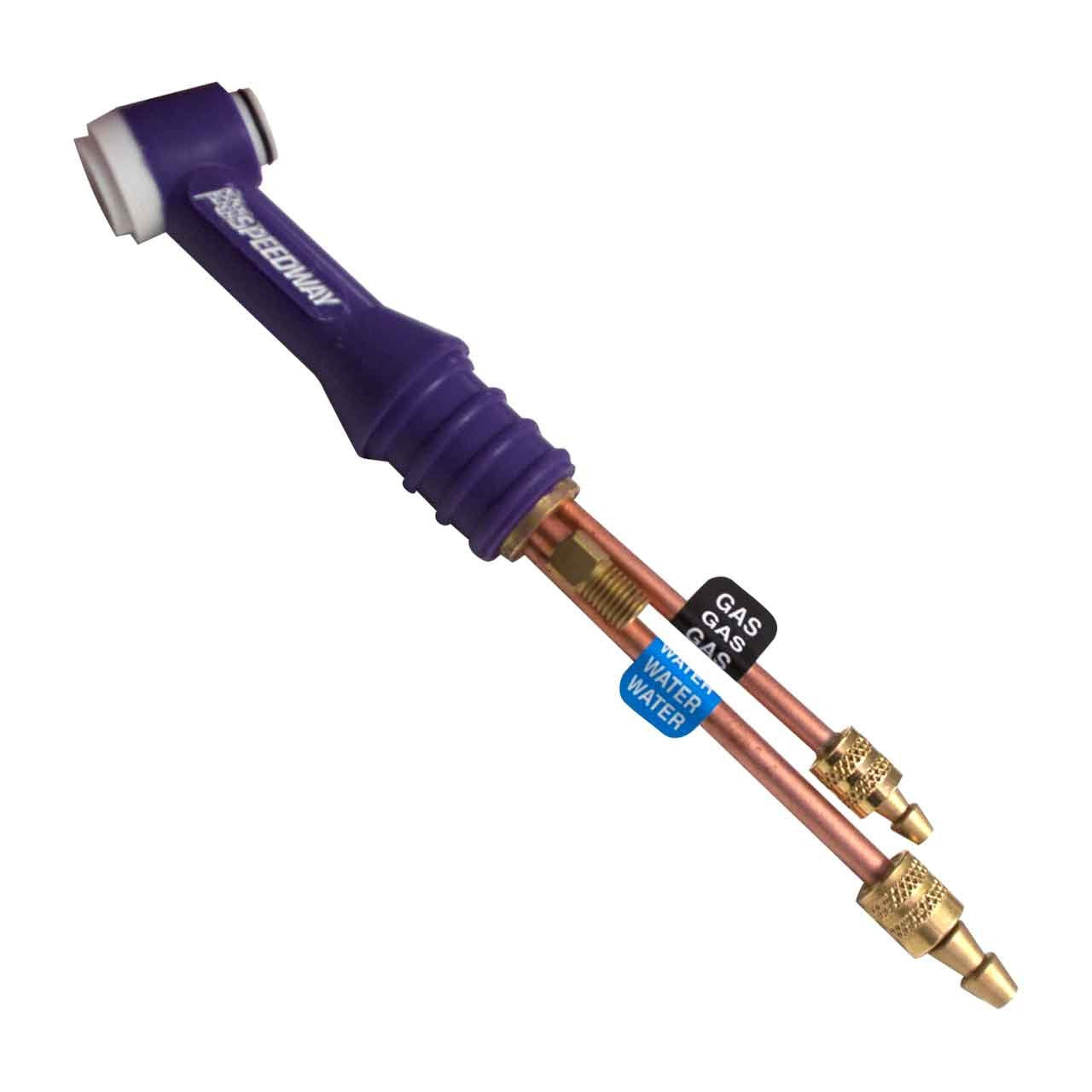
The Weldtec Speedway SW-320 Torch Body, Rigid, Water, 320A is a TIG torch body built for water-cooled service and rigid-body handling. For buyers, maintenance teams, and welders, the main question is not whether the torch body is “high performance,” but whether it matches the actual duty cycle, cooling setup, and operator needs in your shop. This breakdown focuses on what to verify before purchase, what to inspect after installation, and where support issues usually show up in service.
Key Takeaways
- The SW-320 is a rigid, water-cooled torch body intended for TIG welding applications.
- The 320A rating is provided in the product name, but the exact rating basis and conditions are Unknown (Verify).
- Rigid torch bodies are generally chosen when straight access and repeatable hand position matter more than torch flex.
- Water cooling adds heat management, but only if the cooler, hoses, and connections are correctly matched and maintained.
- Before buying, verify the torch body interface, hose routing, and the rest of the torch package so you do not end up with a partial fit issue.
What this torch body is for
As listed, the SW-320 is a torch body only. That matters for buyers. A torch body is not the full torch setup, and it does not eliminate the need to verify the rest of the system: power cable, water lines, gas delivery, back-end connections, and consumable compatibility. In a maintenance environment, the most common mistake is assuming a torch body will integrate with whatever is already on the cart. That assumption should be checked, not trusted.
The rigid-body design is usually best when the operator wants stable positioning and direct access to the weld area. If the application needs more bend or a highly flexible feel, compare the SW-320 against the complete torch kit options and do not assume rigid is the best fit for every job.
Practical buyer checks before ordering
- Check the duty cycle need. Verify whether your application truly needs a water-cooled torch body. If welding time, current, or heat load are not demanding, the added complexity may not be justified.
- Inspect the machine-side setup. Confirm your TIG power source and cooler arrangement support a water-cooled torch body. Unknown (Verify) for exact connector requirements.
- Verify hose and cable routing. A rigid body may work well on the bench but create interference in tight fixtures or field work.
- Confirm consumable family. Do not assume the torch body matches the same cup, collet, or gas lens setup as another torch without checking the correct parts list.
- Review the full package. If you only need a replacement torch body, make sure the rest of the torch assembly remains serviceable and compatible.
Inspection and setup checks
Use a simple verify routine when the torch arrives or when it comes back from service.
- Check exterior condition: inspect the torch body for dents, crushed sections, heat damage, or signs of impact.
- Inspect the fittings: verify that threaded ends, adapters, and hose ends are clean and undamaged.
- Verify water flow path: confirm the supply and return lines are routed correctly and not reversed. If the machine setup is not clearly labeled, mark it.
- Check for leaks: pressure test or run the cooler at low risk conditions first. Any moisture at fittings should be corrected before welding.
- Inspect the grip and handle area: look for looseness, cracked insulation, or worn spots that could affect handling.
- Verify torch head alignment: on a rigid body, the operator should not need to force position or compensate for obvious twist.
Troubleshooting support: common issues and what to check
Issue: Torch runs hot faster than expected.
Check the cooler operation first. Verify coolant level, pump output, hose restriction, and whether flow is reaching the torch. Confirm the torch is actually plumbed as a water-cooled body and not partially blocked. Also verify the welding current and arc-on time against the actual application. If the torch is being run beyond its practical setup, the problem is not the torch body alone.Issue: Poor gas coverage.
Inspect the gas line, seals, and front-end consumables. Verify that the torch body connections are tight and that there is no damage at the hose assembly. A torch body can be sound while a bad seal or damaged consumable creates the defect.Issue: Water leaking at a fitting.
Check hose seating, O-rings if used in your configuration, and any adapter interfaces. Dry the area, restart the system, and observe where the leak begins. Do not keep welding with an active leak.Issue: Torch feels awkward in hand.
Confirm the torch body type is right for the work position. A rigid body can improve control in some setups and be uncomfortable in others. Verify whether the issue is torch geometry, hose drag, or cable management before replacing parts.Product and parts section
This article covers the Weldtec Speedway SW-320 Torch Body, Rigid, Water, 320A as listed in the ArcWeld product source. The provided product information identifies it as a rigid, water-cooled torch body in the Speedway Series. Other specifications beyond that description are Unknown (Verify).
For direct product reference, use the ArcWeld listing here:
If your job requires a complete torch kit rather than the body alone, compare the SW-320 body to the linked related overview below before you commit to a service path or replacement strategy.
Safety notes
- Always lock out or de-energize equipment before changing torch parts or inspecting electrical connections.
- Water-cooled systems can leak. Verify connections before striking an arc.
- Do not touch hot front-end parts immediately after welding.
- Use the correct PPE for TIG work, including eye protection and gloves appropriate to the task.
- If the torch body, cable, or hose assembly shows damage, remove it from service until repaired or replaced.
FAQ
Is the SW-320 a complete torch setup?
No. The provided source identifies it as a torch body. Verify the rest of the TIG torch assembly separately.Can I assume it will fit my existing TIG machine?
No. Compatibility is Unknown (Verify) unless you confirm the machine-side connectors, cooler requirements, and hose routing against your existing setup.Does the 320A rating mean it will run that output in every job?
No. The rating appears in the product name, but the actual rating basis, duty cycle conditions, and application limits are Unknown (Verify).Should I choose a rigid torch body over a flexible one?
Only if the job benefits from stable hand position and direct access. For tight or awkward weld positions, compare the torch body style against the actual work area.Sources Checked
- ArcWeld product page: Weldtec Speedway SW-320 Torch Body, Rigid, Water, 320A
- Internal related article: Weldtec Speedway SW-320-25DX Deluxe Water-Cooled TIG Torch Kit, 25’, Braided – A Comprehensive Overview
Related Arc Weld Part
Weldtec Speedway SW-320 Torch Body, Rigid, Water, 320A
Weldtec Speedway SW-320 Torch Body – Rigid, Water-Cooled, 320A The Weldtec Speedway SW-320 is a high-performance TIG torch body built to handle demanding welding applications. Rated for 320 amps and water-cooled for maximum heat control, this rigid-body torch is part of the Speedway Series—known for reliability, comfort, and durability. Whether you're working in a shop or field environment, the SW-320 delivers con…
View at Arc Weld StoreRelated Weld Support Guides