Category: MIG Welding Support

  • 169-728 Miller Style M-25 Gas Diffuser/Tip Adapter – Arc Weld by Masterweld Pack of (2): Replacement Part Breakdown

    If you are replacing a consumable or wear component on a MIG gun, the first job is confirming the exact part form and the gun it belongs on. The 169-728 Miller Style M-25 Gas Diffuser/Tip Adapter – Arc Weld by Masterweld Pack of (2) is listed as a replacement part, but purchase decisions should still start with a fit check. Do not assume a “style” match is enough. Verify the gun model, thread/interface details, and the tip and diffuser arrangement already in service.

    This guide is written for welders, maintenance buyers, and support teams who need a practical breakdown before ordering. Use it to inspect the current setup, confirm replacement need, and reduce downtime from mismatched parts.

    Key Takeaways

    • Confirm the MIG gun model before ordering. “Miller style M-25” is not the same as a verified fit for every gun carrying a similar label.
    • Inspect the existing diffuser/tip adapter for burnback, spatter damage, thread wear, and heat distortion.
    • Replace parts when cleaning no longer restores stable tip seating or gas flow consistency.
    • Unknown (Verify): exact dimensions, thread pitch, material, and compatibility beyond the product listing.
    • Use the product listing as a replacement-part reference, not as a substitute for machine documentation.

    What this part does

    A gas diffuser/tip adapter in a MIG gun helps support the consumable tip and routes shielding gas through the front-end assembly. In practical terms, it is part of the interface between the neck, the contact tip, and the gas path. When it is worn, loose, or damaged, the operator may see unstable arc performance, erratic shielding, or recurring burnback at the front end.

    Because the product is identified as a “Miller style M-25” part, the correct next step is to compare it against the exact front-end assembly already installed on the gun. Do not rely on appearance alone. Some parts look similar but differ in fit, thread pattern, or front-end stack height. Unknown (Verify): exact compatibility with your specific gun and consumable package.

    Check, inspect, verify before you order

    Check: the gun model tag, maintenance records, and the part removed from service. Confirm whether the existing assembly is actually a gas diffuser, a tip adapter, or a combined front-end component.

    Inspect: the threaded areas, seating faces, and gas passages. Look for heavy spatter buildup, galling, flattening, cracks, and heat discoloration that changes how the tip seats.

    Verify: that the replacement part matches the front-end configuration on your machine. Match against the gun manual or current bill of materials. If there is any uncertainty, mark the current part as Unknown (Verify) until the model is confirmed.

    Troubleshooting support section

    If you are replacing this part because the gun is not performing correctly, work through the front-end assembly in order.

    • Check the contact tip first. Tip wear or incorrect installation can mimic diffuser problems.
    • Inspect the diffuser/tip adapter for spatter bridge. Heavy spatter can interrupt gas flow and tip seating.
    • Verify the nozzle condition. A damaged nozzle can cause shielding issues that are not caused by the diffuser itself.
    • Check for burnback damage. If the wire fused to the front end, replace the affected parts as a set if required by condition. Unknown (Verify): whether adjacent parts must also be replaced in your application.
    • Inspect the neck connection. If the neck is loose or damaged, a new diffuser will not fix the root issue.

    For repeated failures, document the duty cycle, wire type, shielding gas, and the maintenance interval. Those factors help identify whether the failure is a consumable wear issue, a setup issue, or a handling problem.

    Replacement-part evaluation

    This item is sold as a pack of two. That may be useful for maintenance stock, but you still need to verify whether your operation uses the part often enough to justify keeping extras on hand. For buyers, the correct question is not just whether the part is available; it is whether the part is confirmed for the gun family in service.

    Before issuing a purchase request, check the following:

    • Existing part number: confirm the removed component carries 169-728 or an equivalent documented identifier.
    • Gun series: verify the front-end assembly is actually M-25 style and not another similar configuration.
    • Consumable pattern: inspect whether the contact tip and diffuser arrangement matches your current setup.
    • Spare-part control: store the part with the gun model, date received, and verification note.

    Unknown (Verify): manufacturer material, plating, and manufacturing tolerances. Do not build procedure decisions around unknown properties.

    Product and parts note

    The only product identification confirmed here is the Amazon registry ASIN and product name supplied in the request: 169-728 Miller Style M-25 Gas Diffuser/Tip Adapter – Arc Weld by Masterweld Pack of (2), ASIN B07Y447KP4. No additional specs, dimensions, or compatibility claims are being made here.

    If you are comparing replacement options, use the product listing as a starting point and cross-check it with the current gun documentation. Do not treat listing language as a universal fit statement. Unknown (Verify): exact cross-compatibility with alternate gun brands or clone assemblies.

    Safety notes

    • Lock out equipment and allow hot parts to cool before disassembly.
    • Wear gloves and eye protection when removing spatter-loaded front-end parts.
    • Do not force threaded parts. Cross-threading can damage the gun neck or adapter.
    • If burnback is present, inspect for embedded wire fragments before returning the gun to service.
    • Use only verified replacement parts for the exact gun configuration.

    FAQ

    Q1: Is this part confirmed to fit every Miller-style M-25 gun?
    A: No. “Miller style” is not the same as universal fit. Verify the actual gun model and front-end assembly before ordering.

    Q2: What are the common signs that a diffuser/tip adapter needs replacement?
    A: Look for stripped threads, burnback damage, heavy spatter buildup, distorted seating faces, and gas flow problems that return after cleaning.

    Q3: Can I replace only this part and reuse the rest of the front end?
    A: Sometimes yes, but only after inspection. If the tip, nozzle, neck, or insulating parts are damaged, replacing one component may not solve the problem.

    Q4: Are the exact dimensions and material confirmed?
    A: Unknown (Verify). Use the supplied listing and your machine documentation for confirmation.

    Sources Checked

    • Provided Amazon registry product entry for ASIN B07Y447KP4
    • Provided topic brief and allowed internal link set

    Internal link: Aluminum ER 5554 3/64″ X 5lb. MIG Welding Wire Spool By Washington Alloy – Weld Support Parts Blog

    Matched Replacement Option

    No products found.

    Disclosure: As an Amazon Associate, Weld Support Parts may earn from qualifying purchases.

    Related Weld Support Guides

  • 169-728 Miller Style M-25 Gas Diffuser/Tip Adapter – Arc Weld by Masterweld Pack of (5): Replacement Part Breakdown

    If you service MIG guns in a shop or maintenance setting, small wear parts matter. The 169-728 Miller Style M-25 Gas Diffuser/Tip Adapter by Arc Weld by Masterweld is sold as a pack of five and is intended as a replacement part reference for M-25 style setups. For buyer and maintenance teams, the main job is not just ordering a part number. It is confirming the gun family, checking wear patterns, and verifying thread, fit, and gas flow performance before you put the torch back in service.

    Key Takeaways

    • This part is listed as a Miller style M-25 gas diffuser/tip adapter. Exact OEM lineage and interchange details should be verified before use.
    • Use the existing worn part as the primary reference for fit, threading, and seating style.
    • Replace the diffuser/tip adapter when you see spatter buildup, burned threads, poor tip seating, or inconsistent gas coverage.
    • If any compatibility detail is uncertain, record it as Unknown (Verify) and compare against the gun manual, the removed part, or your purchasing record.

    What This Part Does

    On a MIG gun, the gas diffuser routes shielding gas to the weld zone and supports the contact tip interface. A tip adapter function can also influence how the contact tip is retained and how well the assembly stays centered. When this part is worn or damaged, the symptoms often show up as erratic arc behavior, excess spatter, poor shielding, or a contact tip that will not seat correctly.

    Do not assume every “M-25 style” part is identical. Verify the gun model, internal threads, and the physical dimensions of the removed part before approving a replacement.

    Inspect Before You Order

    Use these checks on the old diffuser/tip adapter before placing the order:

    1. Check the gun model. Confirm the MIG gun is an M-25 style or equivalent reference. If the gun tag is missing, verify from the welding machine record or manual.
    2. Inspect the threads. Look for torn, flattened, or packed threads. If the thread form is not obvious, mark it as Unknown (Verify).
    3. Inspect the seating surface. Look for arc strikes, heat distortion, or spatter that could prevent proper contact tip engagement.
    4. Inspect gas passages. Blocked passages reduce shielding gas flow and can cause porosity. Cleanable blockage is one thing; cracked or burned-through material is replacement territory.
    5. Verify tip retention. If the contact tip rocks, loosens, or will not tighten consistently, the adapter may be worn.

    Troubleshooting: When to Replace

    Use a structured check/inspect/verify process:

    • Check weld appearance for porosity, soot, or unstable arc starts.
    • Inspect the diffuser and tip adapter for spatter accumulation, overheating marks, and damaged threads.
    • Verify gas flow at the nozzle and confirm the issue is not upstream in the liner, hose, regulator, or machine settings.

    If the gas diffuser is physically damaged, replacement is usually faster and more reliable than cleaning. If the issue disappears after cleaning but returns quickly, the part may be at the end of service life.

    Product / Parts Section

    The listed item is the 169-728 Miller Style M-25 Gas Diffuser/Tip Adapter – Arc Weld by Masterweld Pack of (5), ASIN B07Y3WC3HM. Use the Amazon product box only as the product reference provided for this draft:

    No products found.

    Because style naming can vary by seller and by torch family, verify the following before purchase or installation:

    • Gun family: Unknown (Verify)
    • Thread pattern: Unknown (Verify)
    • Material: Unknown (Verify)
    • Compatibility with specific Miller gun variants: Unknown (Verify)
    • Pack count: Five pieces, as listed in the product name

    For maintenance buyers, pack pricing and supply planning should be handled from the order record, not assumed from the product title.

    How to Verify Fit in the Shop

    Before the part is released to production, perform a bench check:

    1. Remove the old diffuser/tip adapter and compare it side by side with the replacement.
    2. Check whether the new part threads in by hand without binding.
    3. Confirm the contact tip seats squarely and does not wobble.
    4. Reassemble the nozzle and perform a gas flow test.
    5. Run a short test bead and inspect for spatter, porosity, and arc stability.

    If any of these checks fail, stop and verify the gun model again. Do not force fit a part that seems close but does not thread or seat correctly.

    Support Note for Buyers and Techs

    For parts like this, the main failure mode is assumption. A “Miller style” description is not the same as confirmed interchangeability across all M-25 variants. Use the removed part, machine documentation, and internal maintenance records to confirm the match. If there is no match data available, document the requirement as Unknown (Verify) rather than guessing.

    Safety Notes

    • Lock out the welder and allow the gun to cool before disassembly.
    • Do not handle hot nozzles, tips, or diffusers without proper PPE.
    • Check for sharp spatter and damaged edges when removing worn parts.
    • Verify shielding gas supply is off before service.
    • Do not use damaged consumables in production if gas coverage or electrical contact is compromised.

    FAQ

    Is this part definitely compatible with every Miller M-25 torch?
    No. The title says Miller style M-25, but exact compatibility is not confirmed here. Verify against the removed part and the gun documentation.

    How do I know the diffuser/tip adapter is worn out?
    Look for stripped threads, burned seating surfaces, heavy spatter buildup, and unstable tip retention. If those symptoms appear, replace it.

    Can I use cleaning instead of replacement?
    Cleaning may help if the issue is only spatter buildup. If the part is warped, cracked, or threads are damaged, replacement is the better option.

    Why buy a pack of five?
    A multi-pack can support maintenance stock, but the actual stocking decision depends on your usage rate and verified interchange needs.

    Sources Checked

    • Provided Amazon ASIN registry reference for B07Y3WC3HM
    • Provided product name: 169-728 Miller Style M-25 Gas Diffuser/Tip Adapter – Arc Weld by Masterweld Pack of (5)
    • Allowed internal link list: Aluminum ER 5554 3/64″ X 5lb. MIG Welding Wire Spool By Washington Alloy – Weld Support Parts Blog

    Related internal reference: Aluminum ER 5554 3/64″ X 5lb. MIG Welding Wire Spool By Washington Alloy – Weld Support Parts Blog

    Disclosure: As an Amazon Associate, Weld Support Parts may earn from qualifying purchases.

    Related Weld Support Guides

  • ESAB Model 33368 30 Amp Nozzle for Plasmarc PT-27 Plasma Torch, Pack of (5): Product Breakdown

    ESAB Model 33368 30 Amp Nozzle for Plasmarc PT-27 Plasma Torch, Pack of (5): Product Breakdown

    Product not found.
    “>ESAB Model 33368 30 Amp Nozzle for Plasmarc PT-27 Plasma Torch, Pack of (5)

    The ESAB Model 33368 30 Amp Nozzle for Plasmarc PT-27 Plasma Torch, Pack of (5) is a consumable part used in plasma cutting. For buyers, maintenance teams, and welding support staff, the main question is not whether it is a replacement part, but whether it matches the torch family, amperage range, and cut duty you actually run on the shop floor. This draft stays focused on that practical check.

    The product page indicates this is a 30 amp nozzle intended for PT-23 and PT-27 Plasmarc plasma torches. Beyond that, the important technical details that affect fit and performance should be verified against the machine manual and the torch consumable chart before purchase or installation. If a detail is not confirmed in the source material, treat it as Unknown (Verify).

    Key Takeaways

    • This is a plasma nozzle consumable, not a universal part.
    • The listed amperage is 30 amp, but the correct operating range still needs verification against your torch and power source.
    • The source product information states PT-23 and PT-27 Plasmarc torch use.
    • As with any nozzle, cut quality depends on air quality, arc start condition, standoff, and wear state.
    • Pack quantity is five nozzles according to the source product listing.

    What This Part Does

    A plasma nozzle constricts and directs the plasma arc. In practical terms, it affects kerf shape, arc concentration, and edge quality. A worn nozzle can show up as wider kerf, rougher edge, harder starts, arc instability, or accelerated wear in related consumables. If your cut quality has changed, do not assume the nozzle is the only cause. Air contamination, electrode wear, damaged swirl components, incorrect stand-off, and double arcing can produce similar symptoms.

    For broader root-cause checks, see the support article on plasma torch nozzle damage causes. For torch-family and consumable matching logic, the plasma drag shield compatibility guide is a useful reference point, even though this part is a nozzle and not a drag shield.

    Buyer Checklist Before Ordering

    Use this as a field check before you place the order or pull stock for a job:

    • Check torch family: Confirm the torch is PT-23 or PT-27 as listed in the source product information.
    • Check amperage: Confirm your application uses a 30 amp nozzle. If the machine is set up differently, the correct match is Unknown (Verify) until confirmed.
    • Inspect the current nozzle: Look for orifice distortion, spatter buildup, ovality, or heat damage.
    • Inspect related parts: Check electrode, retaining cap, swirl ring or equivalent torch components, and air passages as applicable to your torch design.
    • Verify cut problem symptoms: If the issue is intermittent arc transfer, poor start consistency, or excessive dross, confirm whether consumable wear is actually the cause.
    • Verify machine settings: Confirm air pressure, cutting speed, stand-off, and polarity per the equipment manual. Unknown (Verify) if manual data is not on hand.

    Support and Troubleshooting Notes

    When a nozzle is replaced too early, the real problem usually stays in the system. Use a simple inspect sequence:

    1) Inspect the nozzle. Remove it and examine the orifice under good light. Check for wash-out, eccentric wear, cracks, or heavy spatter. If the opening no longer looks uniform, replacement is justified.

    2) Inspect the electrode. A damaged electrode can create arc instability that looks like nozzle failure. Replace related consumables as a set when wear is obvious or when the torch manual recommends it.

    3) Inspect air quality. Moisture, oil, and dirt in the air supply shorten consumable life. Verify dryer function, filter condition, and regulator behavior. If air quality has not been measured recently, it is Unknown (Verify).

    4) Verify torch assembly condition. Check for damaged threads, loose fit, worn retaining parts, and signs of double arcing. If the consumable stack does not seat correctly, the nozzle will not run as expected.

    5) Verify cut setup. Wrong travel speed or stand-off can destroy a new nozzle quickly. If the cut profile is poor immediately after installation, the issue may be setup rather than part quality.

    Product / Parts Section

    The source product information identifies the part as ESAB Model 33368 30 Amp Nozzle for Plasmarc PT-27 Plasma Torch, Pack of (5). The product summary also states use with PT-23 and PT-27 Plasmarc torches. No additional verified specs were provided in the source material, so any further material, dimensions, or certifications are Unknown (Verify).

    For sourcing support, the product can be reviewed through the provided ArcWeld listing: Product not found.

    “>ESAB Model 33368 30 Amp Nozzle for Plasmarc PT-27 Plasma Torch, Pack of (5). Use the listing as the product reference, then verify torch compatibility and amperage in the machine documentation before deployment.

    How to Verify Fit in the Shop

    Before issuing the part, run these checks:

    • Match the torch model: PT-23 or PT-27 per the source listing.
    • Match the consumable shape: Compare the old nozzle to the new one visually and by seating style.
    • Confirm the installation stack: Nozzle, electrode, and adjacent consumables should assemble without force.
    • Test on scrap: Make a short cut on comparable material before releasing the torch back to production.

    Safety Notes

    • De-energize the system before changing consumables.
    • Do not inspect the plasma arc directly.
    • Wear eye and hand protection during part removal and test cuts.
    • Verify compressed air condition before use. Contaminated air can shorten consumable life and affect operator safety.
    • If the torch shows repeated double arcing or abnormal noise, stop and inspect the full torch stack before continuing.

    FAQ

    Is this nozzle only for the PT-27?
    The source product information also states PT-23 compatibility. Verify the actual torch model and consumable chart before ordering.

    Can I use this nozzle at amperage other than 30 amp?
    The listing identifies it as a 30 amp nozzle. Other amperage use is Unknown (Verify) unless confirmed by the torch and power source documentation.

    What causes a new nozzle to fail quickly?
    Common causes include poor air quality, incorrect stand-off, damaged electrode parts, double arcing, and cutting too fast or too slow. Check the full system, not just the nozzle.

    Should I replace only the nozzle?
    Not always. If the electrode or other consumables are also worn, replace the worn set as a group according to the torch manual.

    Sources Checked

    • ArcWeld product listing: ESAB Model 33368 30 Amp Nozzle for Plasmarc PT-27 Plasma Torch, Pack of (5)
    • Internal support article: Plasma Torch Nozzle Damage Causes: Orifice Wear, Double Arcing, Piercing, and Air Problems
    • Internal support article: Plasma Drag Shield Compatibility Guide: Torch Family, Amperage, Nozzle, Retaining Cap, and Cut Mode Checks

    Final note: treat this part as a consumable matched to a specific torch system. Verify torch model, amperage, and assembly details before purchase and before installation. If any technical detail is not confirmed by source material or machine documentation, mark it Unknown (Verify).

    Related Arc Weld Part

    ESAB Model 33368 30 Amp Nozzle for Plasmarc PT-27 Plasma Torch, Pack of (5)

    ESAB Model 33368 30 Amp Nozzle for Plasmarc PT-27 Plasma Torch, Pack of (5)

    ESAB 33368 – 30 Amp Plasma Nozzle for Plasmarc PT-27 Torch (5-Pack) The ESAB 33368 is a 30 amp nozzle designed for use with PT-23 and PT-27 Plasmarc plasma torches. Engineered for clean, efficient cuts in light to medium-gauge metal, this nozzle delivers consistent arc stability and cut quality. Each pack contains five OEM-grade nozzles, ensuring reliable performance and compatibility with ESAB plasma systems. Spe…

    View at Arc Weld Store

    Related Weld Support Guides

  • Torch Gun Nozzle Insulators – 34ct insulator [Set of 2]: Product Breakdown

    Torch Gun Nozzle Insulators – 34ct insulator [Set of 2]: Product Breakdown

    Product not found.
    “>Torch Gun Nozzle Insulators - 34ct insulator [Set of 2]

    Torch Gun Nozzle Insulators – 34ct insulator [Set of 2] are small support parts, but they matter. In MIG gun service, the nozzle insulator helps separate the nozzle from the rest of the torch assembly and support consistent fit at the front end of the gun. When this part wears, cracks, or is installed incorrectly, operators usually notice fit problems before they see a complete failure. That makes inspection important during routine consumable checks.

    This breakdown stays focused on what can be verified from the product listing and on practical shop checks. If you are buying for maintenance stock, use the checks below to confirm you are replacing the correct part before you order in volume.

    Key Takeaways

    What This Part Does

    A nozzle insulator is a front-end torch support component. In service, it helps maintain separation and positioning around the nozzle area. That matters because the front end of the gun sees heat, spatter, and repeated handling. Even if the part is light and small, it can still affect how the nozzle seats and how stable the consumable stack feels during operation.

    From a maintenance standpoint, this is the kind of part that is easiest to overlook until the nozzle starts feeling loose, the front end does not assemble smoothly, or the operator reports repeated consumable mismatch. When that happens, inspect the part before changing larger torch components.

    Product / Parts Section

    Product: Torch Gun Nozzle Insulators – 34ct insulator [Set of 2]

    Source listing note: 100-34CT

    Listed weight: 0.01 lb

    Compatibility: Unknown (Verify)

    Assembly details: Set of 2 as listed

    Use the ArcWeld product page as the reference point for the listing only. Do not assume the part will fit a specific gun series unless your existing torch parts match the same design and part reference.

    Product not found.

    “>View the ArcWeld product listing

    How to Inspect the Part in the Shop

    Use a simple inspection sequence during torch maintenance:

    1. Power down and isolate the equipment. Verify the machine is off and the gun is safe to handle.
    2. Remove the nozzle. Inspect the insulator for heat damage, cracking, hardening, or carbonized buildup.
    3. Check the seating surfaces. Verify the insulator sits flat and does not rock or bind when installed.
    4. Inspect for spatter intrusion. Excess spatter can deform the front-end fit and may be a sign the part should be replaced.
    5. Compare against the old part. Verify shape, mounting profile, and thickness against the removed insulator before installing the new one.
    6. Test the assembly by hand. Reinstall the nozzle and confirm the front end assembles without forcing the parts.

    If the part does not seat cleanly, stop and verify torch model, nozzle type, and the full consumable stack. Do not force a fit.

    Troubleshooting Support

    Problem: Nozzle feels loose after replacement.
    Check the insulator orientation first. Inspect the nozzle and contact surfaces for spatter buildup. Verify the torch model and the part reference before assuming the new part is defective.

    Problem: Front end overheats faster than expected.
    Inspect for damaged insulation, heavy spatter, and poor nozzle seating. Verify that the gun is assembled with the correct consumables and that the front end is clean.

    Problem: Consumables do not assemble smoothly.
    Check for distortion, debris, or carbon deposits. Verify that the nozzle, diffuser, and insulator set are the correct matched parts for the torch.

    Problem: Repeated part failures in short service intervals.
    Inspect operator technique, spatter levels, and duty cycle conditions. Verify that the front-end components are not being damaged by impact, abuse, or incorrect installation.

    Check / Inspect / Verify Before Ordering

    Related Welding Support Reference

    If you are also checking wire selection for a MIG setup, use the Weld Support Parts blog post below as a starting point for a wire discussion. It is a selection reference, not a procedure approval:

    Aluminum ER 5554 3/64″ X 5lb. MIG Welding Wire Spool By Washington Alloy – Weld Support Parts Blog

    For torch consumable context, this related TIG consumables breakdown may also be useful when comparing how front-end parts are organized in a complete torch system:

    17-Piece TIG Welding Torch Kit for WP-17/18/26: Complete Consumables Breakdown

    Safety Notes

    FAQ

    Q: What is this part used for?
    A: It is a torch gun nozzle insulator used at the front end of the MIG gun assembly. Exact torch compatibility is Unknown (Verify).

    Q: Can I buy this by visual match alone?
    A: No. Verify the torch model, nozzle family, and old part profile before ordering.

    Q: Is this a complete torch consumable kit?
    A: No. It is a support part listed as a 34ct insulator [Set of 2], not a complete torch assembly.

    Q: What should I inspect if the new part does not fit?
    A: Check the nozzle, diffuser, and front-end seating surfaces for wear or spatter, then verify the torch model and part reference.

    Sources Checked

    All uncertain technical details are marked Unknown (Verify). No compatibility claims, pricing, or certification claims are made beyond the provided source material.

    Related Arc Weld Part

    Torch Gun Nozzle Insulators - 34ct insulator [Set of 2]

    Torch Gun Nozzle Insulators – 34ct insulator [Set of 2]

    100-34CT Dimensions: -Overall Product Weight:0.01 lb

    View at Arc Weld Store

    Related Weld Support Guides

  • Tweco Liner 42-3035-15, .035-.045, 15′ Conduit 1420-1113 – 1 Piece: Product Breakdown

    Tweco Liner 42-3035-15, .035-.045, 15′ Conduit 1420-1113 – 1 Piece: Product Breakdown

    Product not found.
    “>Tweco Liner 42-3035-15, .035-.045, 15' Conduit 1420-1113 - 1 Piece

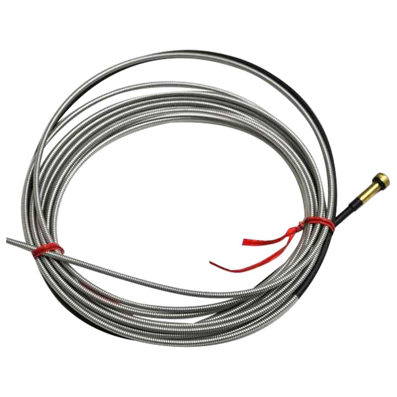
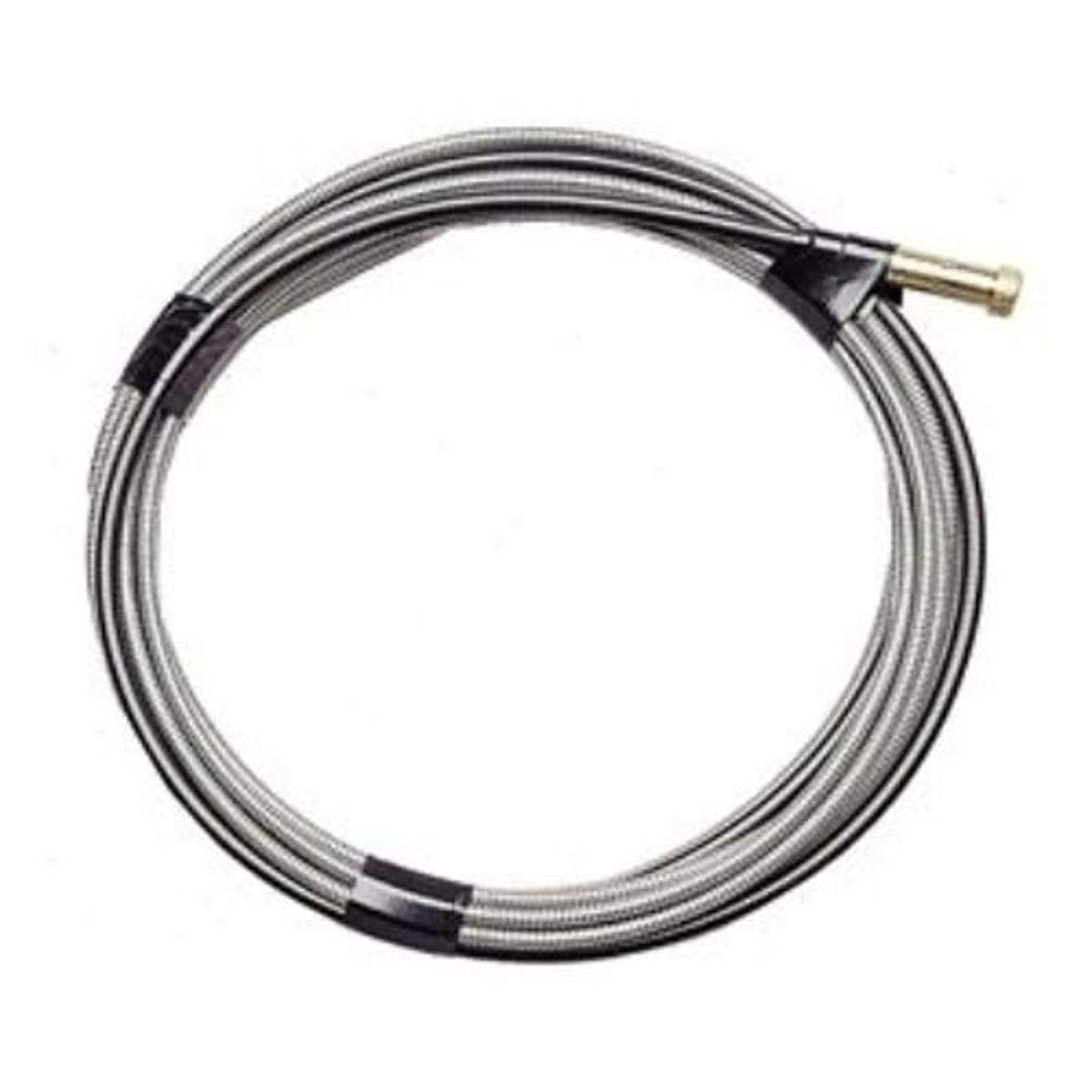
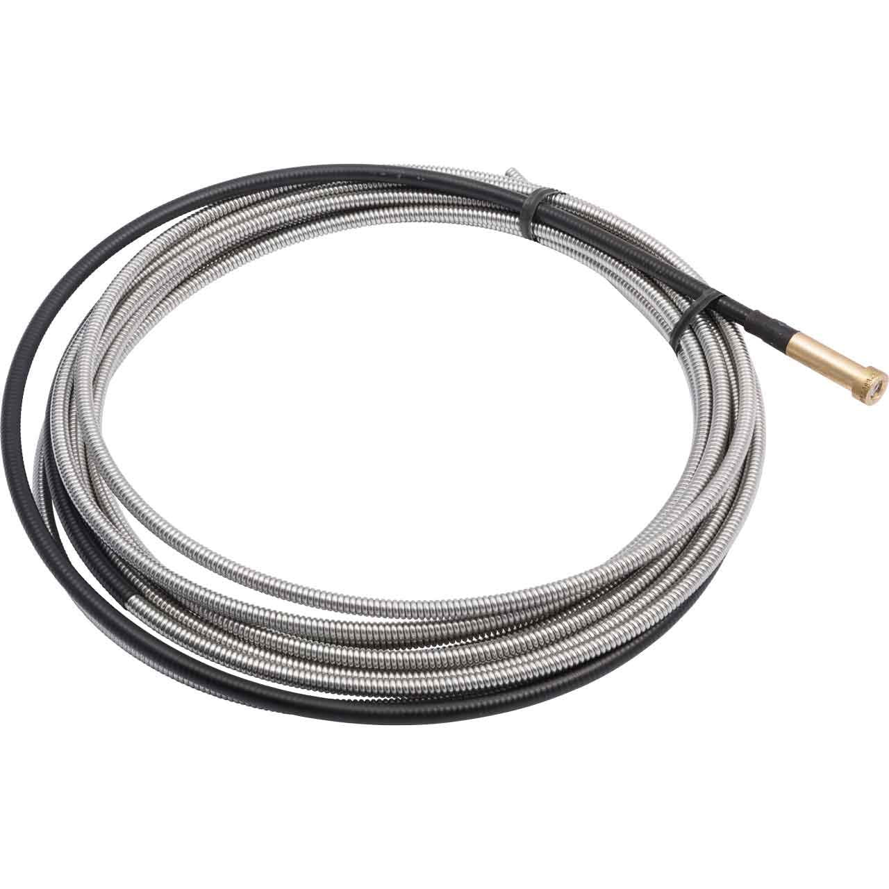
    Wire-feeding problems in MIG welding are often traced back to the liner before operators start changing contact tips, drive rolls, or wire spools. The Tweco Liner 42-3035-15, .035-.045, 15′ Conduit 1420-1113 – 1 Piece is a conduit liner assembly intended for MIG gun wire guidance. Based on the product information provided, it is described as a Tweco Universal Conduit liner that is ready to use out of the box and uses a crimped wire guide that is common to all brands of MIG guns. It is listed for use with Eliminator, Traditional, and Spray Master-style guns.

    This article breaks down what to check before installation, what to verify during a replacement, and how to troubleshoot feeding issues without guessing. If you are buying for maintenance, production support, or shop repair, the goal is simple: confirm fit, confirm wire size, confirm routing, and confirm the liner is the actual problem before you replace parts.

    Key Takeaways

    What This Part Is For

    A conduit liner supports wire travel from the feeder through the gun cable to the contact tip. When the liner wears, becomes contaminated, or is damaged during installation, the wire can drag, hesitate, or buckle. That can look like a drive roll problem or a spool issue, but the liner is often the first place to inspect.

    The source description identifies this as a universal common crimped wire guide for MIG guns. That does not remove the need to verify gun type, liner path, wire diameter, and overall cable condition. Universal wording should be treated as a starting point, not a final compatibility approval.

    Before You Order or Install

    Check: the gun model currently in service, the wire diameter being run, and the existing liner style. If the machine uses a separate conduit liner system, confirm whether the current setup is designed around this style of replacement.

    Inspect: the drive rolls, inlet guide, torch neck, and contact tip before replacing the liner. A worn liner is only one source of feeding problems. Replacing a liner without checking these other points can leave the root issue unchanged.

    Verify: the cable path is not sharply bent, crushed, or heat damaged. Even a new liner can feed poorly if the cable jacket is damaged or the gun is routed through a tight radius.

    Replacement and Setup Checks

    Check: that the new liner matches the wire size range needed for the job. The provided product title lists .035-.045. If your application is outside that range, do not assume it will feed correctly. Unknown (Verify).

    Inspect: the old liner for copper dust, shavings, flattened sections, rust, or burnback damage. These are common indicators that the liner is no longer providing a smooth wire path.

    Verify: cut length, trim condition, and seating at both ends during installation. A liner that is too long, poorly trimmed, or not seated against the gun components can create drag and inconsistent feed.

    Check: that the wire enters the liner without catching at the feeder end. If the wire wants to buckle at startup, do not force it. Re-check drive roll tension, inlet alignment, and liner entry.

    Troubleshooting Support

    If feeding problems continue after liner replacement, work through the system in order.

    1. Check the wire path.
    Inspect the spool, feeder outlet, inlet guide, liner entry, gun cable, and tip. Any point with obstruction can cause drag.

    2. Inspect drive roll pressure.
    Too much tension can deform the wire and create feeding issues. Too little tension can cause slipping. Adjust only after confirming the liner path is clear.

    3. Verify the contact tip condition.
    A worn or overheated tip can mimic liner problems. If the wire feeds freely through the liner but hangs at the end, the tip may be part of the restriction.

    4. Check for contamination.
    Dirt, metal dust, and fragments from wire can collect in the liner. If the liner was exposed during maintenance, verify that no debris entered the conduit during installation.

    5. Inspect the gun cable routing.
    If the cable is bent too tightly, feeding will suffer even with a new liner. Verify that the gun can move through its normal work envelope without binding.

    Product and Parts Notes

    The provided product information says the liner is ready to use right out of the box and is packaged as one piece. The source also describes it as a Tweco Universal Conduit liner. Those are the only packaging and use details that should be relied on here. No additional dimensions, certifications, materials, or cross-brand approvals are confirmed in the provided source, so those details remain Unknown (Verify).

    If you are selecting this part for a maintenance shelf, the practical buying question is whether your shop replaces the entire liner assembly at once or trims and fits liners in-house. The source indicates a ready-to-use item, which supports field replacement, but installation practice still depends on the gun setup and shop procedure.

    Safety Notes

    Related Selection Starting Point

    If your maintenance task also includes filler metal review, use the internal WSP content below as a selection starting point only. It is not a procedure approval and does not replace WPS review or job-specific qualification requirements.

    FAQ

    Is the Tweco Liner 42-3035-15 a universal liner?
    The provided product description says it is a Tweco Universal Conduit liner and references broad MIG gun style compatibility. Final fit still needs to be verified on the actual gun and feeder setup in service.

    What wire size is this liner intended for?
    The product title lists .035-.045. If your wire is outside that range, compatibility is Unknown (Verify).

    What should I inspect before blaming the liner for feed issues?
    Check the drive rolls, inlet guide, contact tip, cable routing, and wire spool condition first. A feeding problem can come from any point in the wire path.

    Does the source confirm all dimensions and certifications?
    No. Only the listed product title and description were provided. Any unlisted technical detail is Unknown (Verify).

    Sources Checked

    Related Arc Weld Part

    Tweco Liner 42-3035-15, .035-.045, 15' Conduit 1420-1113 - 1 Piece

    Tweco Liner 42-3035-15, .035-.045, 15' Conduit 1420-1113 – 1 Piece

    Each conduit liner wire has a crimped wire guide that is universal common to all brands of MIG guns. For all guns (Eliminator, Traditional and Spray Masterâ„ styles). Tweco Universal Conduit liner is ready to use right out of the box. Package of (1)

    View at Arc Weld Store

    Related Weld Support Guides

  • Washington Alloy 2 Lb. Spool Mig Welding Wire 308L Stainless Steel (.035 X 2lb.): Replacement Part Breakdown

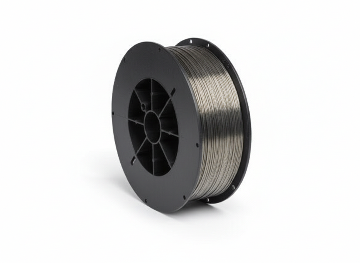
    This guide covers the Washington Alloy 2 lb. spool MIG welding wire in 308L stainless steel, .035 diameter, as a replacement consumable for maintenance and fabrication work. The main question is not whether the wire exists on the shelf, but whether it is the right filler metal for the job, the feeder, and the base metal condition. For stainless work, selection errors usually show up as poor wetting, slag or soot issues, contamination, or welds that do not meet the service requirement.

    Product reference: Washington Alloy 2 Lb. Spool Mig Welding Wire 308L Stainless Steel (.035 X 2lb.) ASIN B081X4F6BV. Use the product page as the item reference only. Do not assume process approval, machine compatibility, or base-metal coverage without checking the actual welding procedure or weld requirement.

    Key Takeaways

    • 308L stainless MIG wire is a filler metal choice, not a universal stainless solution.
    • .035 wire size must match the feeder setup, drive rolls, liner, and contact tip condition.
    • Use it only when the weld requirement, shielding gas, and base metal call for 308L stainless filler.
    • Verify storage and handling first; stainless wire contamination can create avoidable defects.
    • If the base metal or procedure is unclear, stop and verify before welding.

    What this wire is used for

    308L stainless filler is commonly selected when joining compatible stainless materials. The “L” designation indicates low carbon, which is used to reduce the risk of sensitization in the weld zone. That does not mean it is interchangeable with every stainless grade or every joint. The correct choice depends on the base metal, service environment, corrosion requirement, and the approved welding procedure. If any of those inputs are unknown, treat the filler selection as Unknown (Verify).

    Check: confirm the base metal grade from drawings, tags, or material certs.
    Inspect: look for contamination, rust, carbon steel residue, oil, or chloride-bearing cleaners.
    Verify: confirm whether the job calls for 308L, 309L, or a different filler before loading the spool.

    Fit-up and machine support checks

    A 2 lb spool in .035 diameter may be correct for bench work, repair work, or light fabrication, but the feeder setup still matters. Do not assume the spool will run well just because it fits the hub. Check the drive rolls, liner, torch cable routing, contact tip size, and tension. If the wire birds-nests, hesitates, or feeds inconsistently, the issue is often mechanical rather than chemical.

    • Check: drive roll groove size against .035 wire.
    • Inspect: liner wear, debris, and sharp bends in the gun cable.
    • Verify: contact tip bore is correct for the wire size and not worn oversize.
    • Check: spool brake tension and feed pressure before changing settings.

    Troubleshooting support section

    If weld quality is inconsistent, isolate the problem in order: material, wire, shielding gas, feeder, then technique. Stainless MIG issues are often traced to poor surface preparation or the wrong gas setup, not the spool itself.

    Common symptoms and what to check

    • Poor bead wetting: Check base-metal cleanliness, joint fit-up, and whether the filler choice matches the job. Verify shielding gas setup.
    • Excessive spatter or soot: Inspect gas coverage, nozzle condition, and stickout. Verify the machine is configured for the process in use.
    • Wire feeding problems: Check liner, drive roll tension, and tip wear. Verify the spool is installed without side loading.
    • Discoloration or contamination: Inspect storage, handling, and whether stainless wire has been exposed to carbon steel dust or moisture.

    Product and parts considerations

    This is a consumable wire product, not a complete system. The spool is only one part of the welding chain. For support teams and buyers, the real replacement question is whether the feeder package, gun parts, and gas setup support stainless wire reliably.

    Before purchasing, confirm the following:

    • Wire diameter: .035
    • Material type: 308L stainless
    • Spool size: 2 lb
    • Machine feed capability for small stainless spools: Unknown (Verify)
    • Shielding gas requirement: Unknown (Verify)
    • Base metal compatibility for the job: Unknown (Verify)

    If any of those values do not match the welding instruction, do not force the part into service. A wire can be physically compatible with the feeder and still be wrong for the weld requirement.

    How to evaluate before you install the spool

    1. Check the label. Confirm the wire type, diameter, and spool weight before opening the package.
    2. Inspect the package. Look for damage, moisture exposure, or visible contamination.
    3. Verify the machine setup. Confirm drive rolls, liner, and tip size for .035 wire.
    4. Clean the work area. Keep stainless wire away from carbon steel grinding dust.
    5. Test feed. Run a short feed test before striking an arc.
    6. Verify weld result. Inspect bead appearance, fusion, and discoloration after the first test weld.

    Internal support references

    For related stainless wire selection guidance, see Best MIG Wire for Stainless Steel (ER308L vs ER309L). That article is a selection reference, not a procedure approval. For surface preparation support, see Stainless Steel Wire Wheel Brush for Welding Surface Prep.

    Related content on stainless welding also includes Best Flux Core Wire for Stainless Steel Welding. Use it only as a comparison point when evaluating process options.

    Safety notes

    • Use approved PPE for MIG welding, including eye, hand, and body protection.
    • Stainless welding can generate fumes that require adequate ventilation or local exhaust.
    • Keep stainless consumables away from carbon steel contamination.
    • Do not rely on general assumptions for process approvals, gas mix, or corrosion performance.
    • Follow the site weld procedure and supervisor instructions where applicable.

    FAQ

    Is this wire automatically correct for all stainless steel jobs?

    No. 308L is a specific stainless filler choice. Confirm the base metal and weld requirement before use. If the specification is not available, mark it as Unknown (Verify).

    Can I use .035 wire in any MIG machine?

    Not automatically. The machine must support the spool format, wire size, liner, drive rolls, and torch configuration. Verify the feeder package before purchase or installation.

    What should I check if the wire feeds poorly?

    Check the drive rolls, liner, contact tip, spool tension, and cable routing first. Feeding problems are often mechanical rather than caused by the wire alloy.

    Does 308L mean the wire is approved for my application?

    No. Alloy designation alone does not approve a weld. The final decision depends on the welding procedure, joint design, service environment, and base metal.

    Sources Checked

    • Amazon product reference for Washington Alloy 2 Lb. Spool Mig Welding Wire 308L Stainless Steel (.035 X 2lb.), ASIN B081X4F6BV
    • Weld Support Parts internal article: Best MIG Wire for Stainless Steel (ER308L vs ER309L)
    • Weld Support Parts internal article: Stainless Steel Wire Wheel Brush for Welding Surface Prep
    • Weld Support Parts internal article: Best Flux Core Wire for Stainless Steel Welding

    Bottom line: treat this spool as a targeted stainless filler metal option, not a universal replacement part. Confirm the job requirements, verify the feeder setup, and keep the wire clean from the moment it is opened.

    Matched Replacement Option

    No products found.

    Disclosure: As an Amazon Associate, Weld Support Parts may earn from qualifying purchases.

    Related Weld Support Guides

  • 000-068 Miller Style M-Series Contact Tip .035 – Arc Weld by Masterweld Pack of (25): Replacement Part Breakdown

    If you are maintaining a MIG gun, the contact tip is a wear item that directly affects arc stability and wire feed consistency. The product listed here is the 000-068 Miller Style M-Series Contact Tip .035 – Arc Weld by Masterweld Pack of (25) for ASIN B07Y3SCYB7. This draft is written as a replacement-part breakdown for buyers and support teams who need a practical way to evaluate a tip before installing it.

    Because tip compatibility can vary by gun, diffuser, neck style, and wire diameter, treat any fitment assumption as Unknown (Verify) unless your equipment manual or parts breakdown confirms it. Do not assume “Miller style” means universal compatibility across all Miller MIG guns.

    Key Takeaways

    • A contact tip is a consumable wear part, not a permanent component.
    • The stated wire size is .035; verify your wire diameter before installation.
    • Fitment depends on the gun model and front-end consumables. Verify against the machine manual or parts list.
    • Poor tip condition can cause inconsistent arc starts, feeding issues, and heat-related wear.
    • Pack quantity is listed as 25 in the product name, but do not assume packaging details beyond the listing title without checking the source page.

    What a Contact Tip Does

    The contact tip transfers welding current to the wire while guiding the wire through the gun’s front end. If the bore is worn, oversized, blocked, or contaminated, the wire can hesitate or arc quality can drop. In maintenance terms, the tip is a small part with a large effect on production consistency.

    How to Evaluate This Part Before Use

    Check: Confirm the wire diameter matches the tip size. For this item, that means .035 wire only unless your procedure and equipment documentation say otherwise.

    Inspect: Look at the tip threads, seating surfaces, bore, and visible finish before installing. Reject damaged, cross-threaded, or contaminated parts.

    Verify: Confirm the front-end components in your gun assembly. A Miller style M-Series label does not by itself confirm exact gun compatibility.

    Check: Compare the replacement tip to the removed tip. Length, shoulder profile, thread style, and seating geometry should match the original part.

    Inspect: After installation, test wire feed by jogging wire at low speed. The wire should pass smoothly without catching or stubbing at the tip.

    Verify: Run a short test weld and confirm arc starts, sound, and wire feeding are stable. If you see burnback, wandering arc, or erratic feed, stop and re-check the tip and liner system.

    Troubleshooting Support: When a Tip Creates Problems

    If a contact tip seems to fail too soon, do not assume the part is the only issue. Tip wear is often caused by system-level problems.

    Check: Wire diameter. A .030 wire in a .035 tip may increase electrical contact variability, while a wire that is too large can bind. Verify actual wire size first.

    Inspect: Liner condition. A dirty or worn liner can push wire inconsistently and accelerate tip wear.

    Check: Drive roll tension and drive roll type. Too much pressure can deform wire and create feed surges; too little can slip.

    Inspect: Gun neck, diffuser, and nozzle alignment. Misalignment can cause off-center wear on the tip.

    Verify: Contact-tip-to-work distance and welding parameters against the procedure. Excessive heat load can shorten consumable life.

    Check: For spatter buildup at the tip opening after each shift. Heavy spatter can block the bore and mimic wire-feed failure.

    Inspect: For burnback evidence. If the wire fuses to the tip, review feed speed, voltage, stickout, and shielding gas coverage.

    Product / Parts Notes

    This page covers the listed Amazon product only: 000-068 Miller Style M-Series Contact Tip .035 – Arc Weld by Masterweld Pack of (25), ASIN B07Y3SCYB7. No additional product specifications should be assumed beyond the provided listing name. Any exact dimensional, thread, material, or certification detail is Unknown (Verify) unless confirmed by the source listing or your internal parts documentation.

    For purchasing teams, the main check is whether your installation needs a Miller style M-Series .035 contact tip and whether the replacement part matches the original front-end setup. If the gun model is uncertain, use the machine’s parts breakdown or a qualified service record before ordering in volume.

    Related Support Reference

    If you need a broader material-selection example for MIG work, use the internal article below as a starting point for wire selection context. It is a support reference, not a procedure approval for this contact tip.

    Safety Notes

    • Lock out welding power when servicing front-end consumables where your site procedure requires it.
    • Allow hot parts to cool before handling.
    • Wear appropriate gloves and eye protection when changing tips or clearing spatter.
    • Do not force a tip into a mismatched diffuser or gun front end.
    • If a consumable repeatedly fails, stop and diagnose the gun assembly instead of cycling parts.

    FAQ

    Is this contact tip only for .035 wire?
    The product name states .035. Verify the wire diameter on your job before use. Do not guess.

    Will a Miller style M-Series tip fit every Miller MIG gun?
    No. That is not safe to assume. Gun model, front-end design, and diffuser style must be verified against the machine parts breakdown.

    What should I check if wire feeding becomes erratic after tip replacement?
    Check liner condition, drive roll setup, wire diameter, spatter buildup, and alignment at the gun front end. Then verify the tip is seated correctly.

    Can I use the same tip for every weld process?
    No. Contact tips are wire-size and gun-specific wear parts. Verify against the exact process and equipment setup.

    Sources Checked

    • Provided Amazon product identifier and listing name for ASIN B07Y3SCYB7
    • Allowed internal link: Weld Support Parts blog article on Aluminum ER 5554 MIG wire

    Note: No WSP lookup page or filler metal finder page was provided in the allowed inputs for this task, so none were included.

    Matched Replacement Option

    No products found.

    Disclosure: As an Amazon Associate, Weld Support Parts may earn from qualifying purchases.

    Related Weld Support Guides

  • S19417 Lincoln Style Nozzle Insulator – Arc Weld by Masterweld Pack of (2): Product Breakdown

    S19417 Lincoln Style Nozzle Insulator – Arc Weld by Masterweld Pack of (2): Product Breakdown

    Product not found.
    “>S19417 Lincoln Style Nozzle Insulator - Arc Weld by Masterweld Pack of (2)

    The S19417 Lincoln Style Nozzle Insulator – Arc Weld by Masterweld Pack of (2) is a MIG support part meant for a specific torch-component stack. According to the product source, it is a Lincoln style nozzle insulator, it is used with the S19418 gas diffuser, and it does not work with PRO series equipment. That is the core buying point: this is a fitment-sensitive part, not a universal consumable.

    For welders and maintenance buyers, the practical question is not only “what is it?” but “will it match the torch setup already in service?” This article keeps the focus on verification steps, fit checks, and support-side troubleshooting before the part is installed into production use.

    Key Takeaways

    What This Part Does

    A nozzle insulator sits in the consumable stack and helps isolate and position the nozzle assembly relative to the diffuser and contact area. In practical shop use, that means the part needs to match the torch design closely. If the geometry is wrong, the nozzle may not seat correctly, or the assembly may not maintain the intended spacing.

    Because the source data only confirms the Lincoln style designation, the S19418 diffuser pairing, and the PRO series exclusion, any deeper compatibility claims are Unknown (Verify). Do not assume it will interchange with all Lincoln-pattern MIG guns or all aftermarket diffuser designs.

    Buyer Check: Before You Order

    Installation and Support Checks

    Use the following checks during replacement and return-to-service:

    If the nozzle will not seat, do not grind the insulator to make it fit. That usually indicates a mismatch in the torch system, a worn diffuser, or the wrong consumable family. Unknown (Verify) for any workaround not stated in the source.

    Troubleshooting Support

    Problem: Nozzle will not seat correctly

    Problem: Consumable life is short

    Problem: Replacements do not match the old part

    Product and Parts Notes

    This article only uses the product information supplied for the Arc Weld by Masterweld listing. The available facts are limited to the Lincoln style nozzle insulator designation, the S19418 diffuser pairing, and the PRO series limitation. No additional specs, dimensions, materials, or certifications are provided here because they were not supplied in the source data.

    If you are building a stocking plan, treat this part as a torch-specific support item. Stocking the wrong consumable family creates avoidable downtime. The quickest support check is to pull one unit from the tool crib and compare it to the torch in service before ordering multiples.

    Product reference:

    S19417 Lincoln Style Nozzle Insulator - Arc Weld by Masterweld Pack of (2)

    S19417 Lincoln Style Nozzle Insulator – Arc Weld by Masterweld Pack of (2)

    Lincoln Style Nozzle Insulator – Use with S19418 gas diffuser – Does not work with PRO series

    View at Arc Weld Store

    Related Reading

    For another consumable example and a different material category, see this internal Weld Support Parts post: Aluminum ER 5554 3/64″ X 5lb. MIG Welding Wire Spool By Washington Alloy – Weld Support Parts Blog. Use it as a reference for how filler metal content is organized, not as a compatibility guide for this nozzle insulator.

    Safety Notes

    FAQ

    Is this insulator universal across Lincoln-style MIG guns?

    No. The source only confirms Lincoln style and the S19418 diffuser pairing. Universal use is Unknown (Verify).

    Can it be used with PRO series equipment?

    No according to the product source. It states that it does not work with PRO series.

    What should I verify before ordering a replacement?

    Check the torch family, confirm the diffuser part number, compare the old part to the new part, and verify that the setup is not a PRO series unit.

    Does the listing provide material, dimensions, or certifications?

    No. Those details are not provided in the source data and should be treated as Unknown (Verify).

    Sources Checked

    Related Weld Support Guides

  • Hobart Spool Gun Support: Parts Lookup and Buying Checks

    Hobart Spool Gun Support: Parts Lookup and Buying Checks

    Hobart Spool Gun Support

    If you are servicing a Hobart spool gun, the main risk is not buying the wrong part by name. The risk is assuming the assembly matches because the tool looks similar. Hobart spool gun support parts can vary by gun model, cable end, wire feed path, and trigger hardware. Before you order anything, identify the exact gun and verify the worn component against the breakdown or lookup page.

    Key Takeaways

    • Start with the exact spool gun model, not just the welder brand.
    • Inspect the consumables, trigger path, liner, and cable first; these are common wear points.
    • Use the WSP lookup page as the first fitment check for Hobart spool gun support parts.
    • If a detail is not shown in the source, mark it Unknown (Verify) before ordering.
    • Do not assume compatibility between SpoolRunner models without confirming the breakdown.

    What this Hobart spool gun support page is for

    The provided WSP lookup page is a support and parts entry point for Hobart spool guns, including SpoolRunner 100, SpoolRunner 150, SpoolRunner 200, and the Hobart 3035-20 spool gun parts breakdown. That makes it useful for maintenance buyers, welders, and repair teams who need to confirm part identity before they place an order.

    Open the Hobart Spool Gun Support page and compare the gun model, assembly view, and the part you are replacing. If the source does not clearly confirm the fitment, stop and verify the serial, model designation, or breakdown reference.

    Buying checks before you order

    Use a simple inspection process before purchasing replacement parts:

    1. Check the model label. Verify the exact spool gun designation on the gun body, cable, or system paperwork.
    2. Inspect the failed part. Look for burn marks, wire drag, cracked housings, loose trigger action, or feed irregularity.
    3. Match the breakdown image. Compare the part position and shape against the WSP lookup page.
    4. Verify any left/right or orientation details. If the source does not state orientation, use Unknown (Verify).
    5. Confirm what is included. Some assemblies are complete and some are partial. Do not assume hardware or fasteners are included unless shown.

    If you are ordering for stock, keep a record of the exact model, failed component, and the reference image used to confirm it. That reduces repeat calls and wrong-ship issues.

    Common support areas to inspect

    For spool gun service, start with the parts that handle wire movement and current transfer:

    • Contact tip and nozzle area: inspect for spatter buildup, heat damage, and poor wire transfer.
    • Gun cable and strain relief: check for external jacket wear, kinks, and movement at the handle entry.
    • Trigger function: verify a consistent click and return. If intermittent, the switch or lead path may need attention.
    • Wire feed path: inspect for drag, liner contamination, or wire birdnesting at the gun end.
    • Drive rolls and spool holder interface: verify the feed path is aligned and the spool rotates smoothly.

    When one of these areas fails, replace only the confirmed failed part if the breakdown supports that approach. If the damage extends into the cable or handle, replacement of a larger assembly may be the correct repair. If the source does not define the repair scope, treat it as Unknown (Verify).

    Troubleshooting checks: inspect, verify, then order

    Issue: wire feed is inconsistent.
    Inspect the spool tension, liner path, tip condition, and any visible cable damage. Verify the wire size and feed setting are appropriate for the gun setup. If the source does not specify wire size compatibility for the part you need, mark it Unknown (Verify).

    Issue: trigger response is intermittent.
    Inspect the trigger movement, handle wear, and lead strain point. Verify the trigger fault is not caused by a damaged cable or loose connector. Do not order a trigger assembly until the breakdown confirms the exact switch style or mounting method.

    Issue: arc start is erratic or weak at the gun.
    Inspect the contact tip, nozzle, cable terminations, and work lead condition. Verify whether the problem is at the gun or in the power source setup. The lookup page is for parts identification, not a welding procedure approval. Use it as a support reference only.

    Using the WSP lookup page

    The Hobart Spool Gun Support page is the primary reference provided for this topic. Use it to confirm the source breakdown for SpoolRunner 100, SpoolRunner 150, SpoolRunner 200, and Hobart 3035-20 spool gun parts. If a part number, assembly name, or fitment note is shown on the page, record it before you order.

    Recommended workflow:

    • Open the lookup page and identify the exact model.
    • Cross-check the visible part against your failed component.
    • Verify whether the item is a full assembly, subassembly, or service part.
    • Use Unknown (Verify) for any detail not stated on the page.

    Go to Hobart Spool Gun Support

    Ordering controls for maintenance buyers

    For shop purchasing, the best control is to require three checks before release:

    • Exact model confirmation
    • Photo or breakdown match
    • Written verification of the failed component

    This is especially important when multiple spool guns are in service. A part may look close but still fail at the interface, cable end, or handle geometry. If the ordering system lacks enough detail, pause the requisition and verify against the source page first.

    Safety notes

    • Disconnect power before opening or handling the gun.
    • Allow hot parts to cool before inspection.
    • Do not test a damaged gun cable under load.
    • Wear proper eye protection when checking the wire path or tip area.
    • If the gun has visible insulation damage, remove it from service until verified.

    FAQ

    Q: Which Hobart spool guns are covered by the WSP support page?
    A: The provided source references SpoolRunner 100, SpoolRunner 150, SpoolRunner 200, and the Hobart 3035-20 spool gun parts breakdown. If a specific fitment is not clearly stated, treat it as Unknown (Verify).

    Q: Can I order by appearance alone?
    A: No. Spool guns can look similar while using different cable ends, trigger parts, or internal feed components. Always verify the exact model and the breakdown match before ordering.

    Q: Is the lookup page a welding procedure guide?
    A: No. It is a parts support and identification reference. Use it to confirm fitment and part identity, not to approve procedure settings or welding parameters.

    Q: What if the part description is incomplete?
    A: Record the missing detail and mark it Unknown (Verify). Then confirm against the gun model, the failure point, and any visible assembly reference before purchase.

    Sources Checked

    Internal links checked:

    • None applicable for this topic

    Product, filler metal, and Amazon references were not used because none were provided for this draft.

    Disclosure: As an Amazon Associate, Weld Support Parts may earn from qualifying purchases.

    Related Weld Support Guides

  • Lincoln KP2743-1-62R Nozzle, Thread-on, 1/8R, 5/8 ID, Pack of (1): Replacement Part Breakdown

    This page breaks down the Lincoln KP2743-1-62R Nozzle, Thread-on, 1/8R, 5/8 ID, Pack of (1) as a replacement part listing for maintenance and purchasing review. Use it to confirm the part number, inspect the current nozzle condition, and verify fit before ordering. Do not assume compatibility from the product name alone. Verify the gun model, consumable family, and thread-on interface against your equipment records.

    Key Takeaways

    • This is a replacement nozzle listing tied to part number KP2743-1-62R.
    • The product title indicates a thread-on nozzle with 1/8R and 5/8 ID; exact machine and gun compatibility is Unknown (Verify).
    • Use the part number first, then verify physical dimensions and thread style against the installed nozzle.
    • Check for spatter buildup, arc instability, and contact-tip-to-nozzle alignment before replacing parts.
    • This article is a buyer and support guide, not a substitute for the gun manual or Lincoln parts list.

    What this part is used for

    A MIG nozzle directs shielding gas and helps protect the weld zone from contamination. In daily use, the nozzle is also exposed to spatter, heat, and handling damage. A worn nozzle may still install on the gun, but it can cause poor gas coverage, excessive cleanup, or inconsistent performance.

    For this listing, the only confirmed product identifier available here is the Amazon ASIN reference B008BJD92S and the product name provided above. Any deeper fitment details, gun series compatibility, or Lincoln cross-reference should be treated as Unknown (Verify) unless confirmed in the manufacturer documentation or your parts database.

    Inspect before you replace

    Before ordering a replacement, inspect the current nozzle and the rest of the front-end consumables. A nozzle problem is sometimes caused by another worn part.

    • Check the nozzle bore: Look for heavy spatter, oval wear, or internal distortion.
    • Inspect the threads: Verify the thread-on connection is clean and not galled, stripped, or cross-threaded.
    • Verify tip centering: Check whether the contact tip sits centered in the nozzle opening.
    • Inspect the diffuser/retainer area: Damage there can make a new nozzle fit poorly.
    • Check for heat discoloration: Excessive heat signs can indicate duty cycle, technique, or fitment issues.

    Troubleshooting support: common signs and checks

    If you are seeing performance problems, use a simple inspection path before authorizing replacement:

    • Gas shielding looks weak: Check for nozzle blockage, loose threads, damaged seals, or incorrect nozzle size. Verify gas flow at the torch separately.
    • Spatter buildup increases quickly: Inspect wire stickout, technique, process settings, and anti-spatter practices. A worn nozzle may be a symptom, not the root cause.
    • Arc starts become inconsistent: Verify contact tip condition, liner condition, and nozzle alignment.
    • Nozzle will not thread on smoothly: Stop and inspect the gun neck threads. Do not force installation.
    • Visible burnback or overheating: Verify consumable fit and process parameters. Unknown (Verify) on exact operational limits for this part without the gun manual.

    Check / Inspect / Verify steps

    1. Check the current nozzle part number if it is still legible.
    2. Inspect the thread-on interface for damage, contamination, or spatter lock.
    3. Verify the gun model and consumable series from the parts diagram or maintenance record.
    4. Check the contact tip size and seating position.
    5. Verify whether the nozzle dimensions on the listing match the nozzle removed from service.

    Product / parts section

    Product: Lincoln KP2743-1-62R Nozzle, Thread-on, 1/8R, 5/8 ID, Pack of (1)

    ASIN reference: B008BJD92S

    Availability, certification, and price: Unknown (Verify)

    Compatibility: Unknown (Verify). Confirm against the exact gun and parts list before purchase.

    View the referenced product listing

    Use the product listing as a procurement reference only. Do not use the title alone to approve fitment for production use. If you are supporting a fleet of welders, compare the installed nozzle against this part number, then confirm the neck thread pattern and the gun family in the service manual.

    Replacement decision: when to replace

    Replace the nozzle when cleaning no longer restores a stable bore, when threads are damaged, or when the part no longer seats correctly. If the nozzle can be cleaned and reinstalled without loss of fit, the support team may choose to keep it in service. Verify the shop standard before returning a worn part to production.

    If a replacement is ordered, record the old part number, the machine ID, and the reason for replacement. That log helps maintenance buyers avoid repeated mismatches.

    Safety notes

    • Allow the torch to cool before handling the nozzle.
    • Wear gloves and eye protection when removing spatter or checking threads.
    • Do not force a threaded consumable into damaged threads.
    • Verify the welding power source is de-energized or in a safe state before service.
    • Use only approved shop procedures for consumable cleaning and replacement.

    FAQ

    Is this nozzle guaranteed to fit my Lincoln gun?

    No. Compatibility is Unknown (Verify) from the information provided here. Confirm the exact gun model and parts diagram before ordering.

    What does thread-on mean?

    It indicates a nozzle that installs by threading onto the torch neck or related front-end assembly. Verify the exact thread form and seating method on your equipment.

    What should I check if the nozzle keeps filling with spatter?

    Check technique, gas coverage, contact tip condition, and any damage to the nozzle bore. A replacement may help, but the root cause may be elsewhere.

    Can I use this listing as an approval for procedure settings?

    No. A parts listing is not a procedure approval. Use the welding procedure, gun manual, and shop standards for operating settings.

    Sources Checked

    • Provided product data for Lincoln KP2743-1-62R Nozzle, Thread-on, 1/8R, 5/8 ID, Pack of (1)
    • Provided ASIN reference: B008BJD92S
    • Provided internal link rules: no WSP lookup link provided, no filler metal link provided

    Note: No WSP lookup page or filler metal finder page was provided in the allowed links for this draft, so none is included here.

    Matched Replacement Option

    No products found.

    Disclosure: As an Amazon Associate, Weld Support Parts may earn from qualifying purchases.

    Related Weld Support Guides

  • Listen with Audible