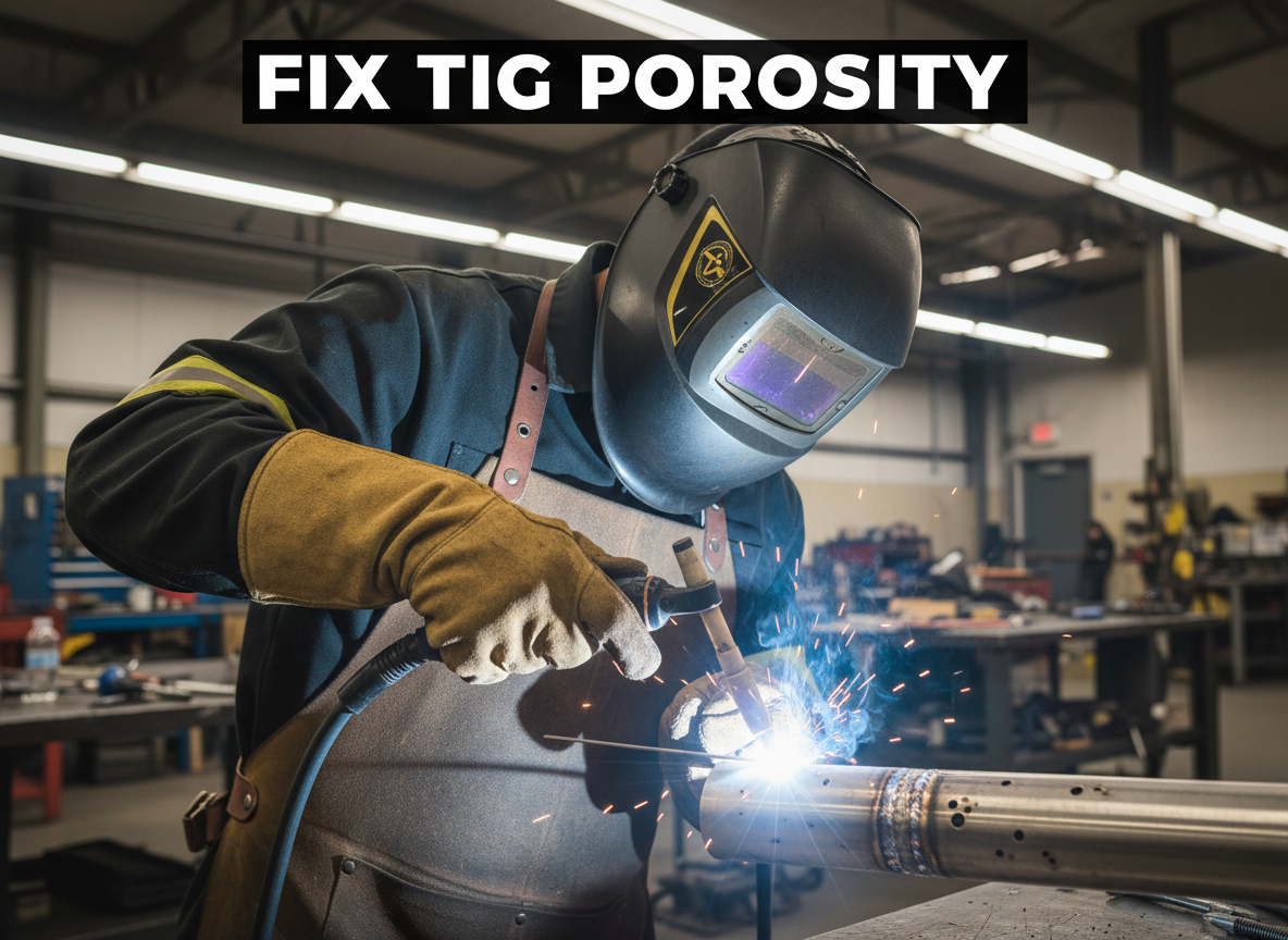
Tag: troubleshooting

  • Plasma Cut Leaving Heavy Dross? Fix It Fast

    Plasma cuts that leave a thick โ€œslagโ€ ridge on the bottom edge are usually telling you the arc isnโ€™t transferring cleanly. If youโ€™re cutting plate and spending more time grinding than cutting, this is the fast checklist to get clean edges again. Hereโ€™s why it happens and how to fix it.

    Symptoms (what youโ€™ll see):

    • Thick dross stuck to theย bottomย of the cut that wonโ€™t chip off easily
    • Rough, jagged cut edge with lots of spatter
    • Noticeable bevel (edge leans) even on straight cuts
    • Arc sounds โ€œlazyโ€ or unstable instead of crisp
    • Consumables discolor quickly or the tip looks out-of-round

    Root Cause (whatโ€™s actually happening):
    Heavy bottom dross is typically caused by a mismatch between travel speed, torch standoff/drag technique, and air quality/pressure. When you move too slowly (or hold the torch too high/too low for the consumables youโ€™re using), the arc lingers and the molten metal doesnโ€™t blow out of the kerf cleanlyโ€”so it re-freezes as dross on the bottom edge.

    Once youโ€™ve run a set of consumables past their useful life, the nozzle orifice can erode and the electrode can pit. That degrades arc shape and airflow, which makes dross and bevel worse even if your technique is decent.

    The Fix (step-by-step):

    1. Confirm your technique: drag vs standoff
      If youโ€™re drag cutting, use aย true drag shield/tip setupย designed for it. If not, maintain a consistent standoff (donโ€™t โ€œfloatโ€ the height).
    2. Increase travel speed slightly (then test)
      Heavy bottom dross commonly means youโ€™re moving too slow. Do a short test cut and speed up until the bottom dross reduces.
    3. Set air pressure/flow to the cutterโ€™s spec (and drain water)
      Wet air and low/unstable pressure destroy cut quality and consumables. Drain the compressor tank and any filter bowl before cutting.
    4. Square up torch angle and keep it steady
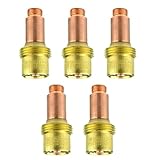
      A slight tilt increases bevel and can push molten metal into the kerf.
    5. Inspect consumables and replace if worn
      If the nozzle hole is egged out, the electrode is pitted, or the shield is packed with spatter, replace the set. Consumables are cheaper than grinding time.

    Real-World Tip:
    Experienced plasma users donโ€™t โ€œfightโ€ dross with more ampsโ€”they do quick test cuts and tune speed first, then height, then air. If the cut suddenly gets worse after it was fine yesterday, they assume air moisture or consumables before anything else.

    Soft CTA (MANDATORY):
    If this keeps happening, your plasma consumables (nozzle/tip + electrode + shield) are likely worn or damaged. See the best replacement options โ†’ [BUYER PAGE LINK PLACEHOLDER]

    Safety Note:
    Wear eye/face protection and glovesโ€”plasma cutting throws hot sparks and slag. Use ANSI Z87.1-rated eye protection and keep flammables clear of the work area.

  • Bad Gas Coverage in MIG Welds? Replace Your Nozzle

    Intro

    Your MIG welds are porous, and you can see the problem: the shielding gas isn’t covering the weld pool. The arc is exposed, hydrogen from the air contaminates the molten metal, and porosity results. The fix isn’t always a regulator adjustmentโ€”it’s often a worn or wrong nozzle. A damaged nozzle restricts gas flow and creates dead zones where the arc isn’t protected. This guide shows you how to diagnose and fix it in 5 minutes.

    Key Takeaways

    • A worn or wrong nozzle restricts gas flow and causes porosity
    • Copper nozzles conduct heat better and last longer than steel
    • Nozzle orifice size affects gas coverage (5/8″ is standard for most MIG guns)
    • Replace nozzles every 100โ€“150 hours of welding or when spatter buildup is visible
    • Always clean the nozzle before replacing itโ€”spatter can be deceptive

    The Problem

    A MIG nozzle is a copper tube that directs shielding gas around the arc. Over time, spatter welds itself to the nozzle, restricting the gas opening. When the orifice is blocked or worn, gas coverage becomes inconsistent.

    What happens:

    • Reduced gas flow: Spatter buildup narrows the opening, starving the arc of protection.
    • Dead zones: Gas doesn’t reach the entire weld pool, leaving unprotected areas.
    • Hydrogen absorption: Unshielded molten metal absorbs hydrogen from air, creating porosity.
    • Weak welds: Porosity reduces tensile strength and can fail inspection.

    You’ll see:

    • Porosity clustered in the weld center or edges
    • Spatter stuck to the nozzle (sometimes thick)
    • Dull or inconsistent arc appearance
    • Gas leaks or hissing sounds around the gun

    Why It Matters

    Porosity is a weld defect. In structural work, it can fail X-ray or ultrasonic inspection. In production, rework costs time and material. A $5 nozzle replacement prevents hours of grinding and rewelding. It also improves weld aesthetics and reduces spatter cleanup.

    The Fix

    1. Power down the welderย and wait 30 seconds.
    2. Unscrew the nozzleย from the gun (usually hand-tight or one-quarter turn).
    3. Inspect the nozzleย for spatter buildup, erosion, or damage.
    4. Clean the nozzleย with a wire brush or soak it in acetone to remove spatter.
    5. If cleaning doesn’t restore flow, install a new nozzleย (hand-tight).
    6. Verify gas flowย by listening for a steady hiss when you pull the trigger.
    7. Test on scrapย to confirm porosity is gone.

    Why This Product Solves It

    The Miller Nozzle Replacement – N-A5800C AccuLock S Large Thread-On Nozzle, 5/8″ Orifice, Copper is a direct replacement for Miller AccuLock S guns. It’s made from high-quality copper, which conducts heat efficiently and resists spatter adhesion better than steel. The 5/8″ orifice is standard for most MIG work, providing optimal gas coverage. A pack of 10 ensures you always have replacements ready.

    Product Link: Miller Nozzle Replacement - N-A5800C AccuLock S Large Thread-On Nozzle, 5/8" Orifice, Copper

    ” target=”_blank” rel=”noreferrer noopener”>
    Miller Nozzle Replacement - N-A5800C AccuLock S Large Thread-On Nozzle, 5/8" Orifice, Copper

    Miller Nozzle Replacement – N-A5800C AccuLock S Large Thread-On Nozzle, 5/8" Orifice, Copper

    $193.27 โ€“ Pack of 10

    In Stock

    View Product

    What to Check Before You Buy

    • Gun compatibility: AccuLock S guns (Miller, Bernard, and clones). Check your gun nameplate.
    • Orifice size: 5/8″ is standard. Some specialty guns use 1/2″ or 3/4″. Verify before ordering.
    • Thread type: Most nozzles are standard thread-on. Older guns may use different connections.
    • Material: Copper is best for durability. Avoid steel nozzles if possible.

    Real-World Use

    A pipeline crew was struggling with porosity on 3/8″ structural steel. They’d checked gas pressure (correct), wire feed (smooth), and base metal (clean). The nozzle had 6 months of spatter buildupโ€”so thick it looked like a different part. After cleaning and replacing with a fresh nozzle, porosity disappeared. The old nozzle’s orifice had shrunk from 5/8″ to nearly 1/2″ due to spatter.

    Common Mistakes

    • Ignoring spatter buildup: Clean before you replace. Sometimes cleaning alone fixes the problem.
    • Using the wrong orifice size: A 1/2″ nozzle won’t provide full coverage. Confirm size before buying.
    • Not checking gas pressure: A worn nozzle combined with low pressure makes porosity worse. Verify regulator setting.
    • Over-tightening the nozzle: Hand-tight is correct. Over-tightening can crack the gun.
    • Forgetting to test: Always run a test bead on scrap before production welding.

    Safety Notes

    Always follow the manufacturer’s instructions and your shop’s safety procedures. If you’re unsure about fitment or ratings, verify before you buy or install.

    Related Reading

  • Title: Worn MIG Contact Tips Causing Porosity? Here’s the Fix

    Intro

    Your MIG welds look porous. You’ve checked your gas flow, cleaned the base metal, and verified your settingsโ€”but the problem persists. The culprit is often sitting right at the end of your gun: a worn contact tip. A damaged or burnt-back contact tip disrupts the electrical arc and wire feed, creating weak welds and wasted material. This guide walks you through diagnosis and replacement in under 10 minutes.

    Key Takeaways

    • Worn contact tips cause porosity, spatter, and inconsistent arc
    • Burnback happens when the tip overheats from improper voltage/wire speed ratio or poor contact
    • Replace tips every 50โ€“100 hours of welding or when you see damage
    • Always match wire size to tip size (e.g., .035″ wire = .035″ tip)
    • Stock replacement tips on hand to avoid downtime

    The Problem

    A contact tip is a small copper tube that carries current to your wire. Over time, it erodes from heat and electrical wear. When the tip is damaged or burnt back, several things go wrong:

    • Poor electrical contact: The wire doesn’t seat properly, creating resistance and weak arc initiation.
    • Inconsistent wire feed: A damaged tip can catch or bind the wire, causing feed stutters.
    • Arc instability: The arc becomes erratic, leading to porosity and spatter.
    • Weld quality drops: Porosity, lack of fusion, and surface defects become common.

    You’ll notice:

    • Spatter clustering around the weld
    • Dull, unstable arc
    • Wire feed hesitation or grinding sounds
    • Visible burnback or erosion on the tip itself

    Why It Matters

    A bad weld costs money. Porosity weakens the joint, spatter wastes time cleaning, and rework eats into your schedule. In structural or pressure-vessel work, porosity can fail inspection. Replacing a $2โ€“5 contact tip takes 2 minutes and prevents hours of rework.

    The Fix

    1. Power down the welderย and wait 30 seconds.
    2. Unscrew the contact tipย from the gun nozzle (usually hand-tight or one-quarter turn with a wrench).
    3. Inspect the old tipย for burnback, erosion, or debris.
    4. Clean the gun nozzleย with a wire brush to remove spatter buildup.
    5. Install the new tip, hand-tight. Don’t over-tighten.
    6. Test the wire feedย before weldingโ€”pull the trigger briefly to confirm smooth feed.
    7. Strike a test beadย on scrap to verify arc stability.

    Why This Product Solves It

    The S19391-1 Lincoln Style Contact Tip .035 – Arc Weld by Masterweld Pack of (25) is a direct replacement for Lincoln-style MIG guns. It’s made from high-quality copper, ensuring reliable electrical conductivity and durability. At .035″ bore, it matches the most common MIG wire size. A pack of 25 means you’ll always have spares on hand, eliminating downtime from tip searches.

    Product Link: S19391-1 Lincoln Style Contact Tip .035 - Arc Weld by Masterweld Pack of (25)

    ” target=”_blank” rel=”noreferrer noopener”>
    S19391-1 Lincoln Style Contact Tip .035 - Arc Weld by Masterweld Pack of (25)

    S19391-1 Lincoln Style Contact Tip .035 – Arc Weld by Masterweld Pack of (25)

    $30.75

    In Stock

    View Product

    What to Check Before You Buy

    • Wire size: Confirm your wire diameter (.023″, .030″, .035″, .045″). Tip size must match.
    • Gun compatibility: Lincoln-style guns (most common). If unsure, check your gun nameplate or contact ArcWeld support.
    • Thread pitch: Most tips are standard, but some older guns differ. Verify fitment before ordering.

    Real-World Use

    A fabrication shop running 8-hour shifts was seeing porosity in every third weld. The operator had replaced the liner and checked gasโ€”but hadn’t changed the contact tip in 3 months. After swapping in fresh tips, arc stability returned immediately, and porosity dropped to near zero. Cost: $3 per tip. Downtime saved: 2 hours per week.

    Common Mistakes

    • Using the wrong tip size: A .045″ tip won’t work with .035″ wire. Confirm before installing.
    • Over-tightening the tip: Hand-tight is correct. Over-tightening can crack the nozzle.
    • Not cleaning the nozzle: Spatter buildup around the tip restricts gas flow and causes porosity.
    • Ignoring the liner: A worn liner can damage a new tip. If tips fail quickly, check the liner next.
    • Skipping the test bead: Always verify arc and feed before production welding.

    Safety Notes

    Always follow the manufacturer’s instructions and your shop’s safety procedures. If you’re unsure about fitment or ratings, verify before you buy or install.

    Related Reading

  • Why Does My Stick Welding Electrode Keep Sticking? (Fix in 15 Minutes)

    Why Does My Stick Welding Electrode Keep Sticking? (Fix in 15 Minutes)

    Your electrode sticks to the workpiece, the arc dies, and you’re left wrestling with the rod. This is one of the most common stick welding problemsโ€”and it’s fixable. Low amperage, poor ground connection, and contaminated metal are the usual culprits. Here’s how to diagnose and fix it fast.

    Key Takeaways

    • Low amperageย is the #1 cause of electrode sticking ($0 fixโ€”just adjust the dial)
    • Poor ground clamp connectionย prevents proper current flow ($15โ€“$40 for a new clamp)
    • Dirty or wet electrodesย create weak arc initiation ($5โ€“$15 for fresh rods)
    • Bad workpiece prepย (rust, mill scale) makes arc unstable ($0โ€“$20 for cleaning tools)
    • Fix time: 5โ€“15 minutes for most issues

    Quick Diagnosis

    What you’re seeing:

    • Rod sticks immediately after striking
    • Arc dies or becomes very weak
    • Difficulty pulling the rod away from the workpiece
    • Electrode melts back into the holder

    Likely causes (ranked by frequency):

    1. Amperage set too low
    2. Ground clamp loose or corroded
    3. Electrode damp or old
    4. Workpiece dirty (rust, paint, mill scale)
    5. Worn electrode holder (weak jaw grip)

    Safety Notes

    • Arc flash hazard: Always wear a helmet with proper shade (ANSI Z87.1 compliant). Sticking electrodes often cause sudden arc flare-ups.
    • Fume exposure: Stick welding produces heavy fumes. Ensure adequate ventilation or use a respirator (ANSI Z136.1 rated for welding fumes).
    • Electrical shock: Disconnect power before inspecting the electrode holder or ground clamp.
    • Hot metal: Electrodes and workpiece are extremely hot. Use insulated gloves and let parts cool before handling.

    Step-by-Step Troubleshooting

    Step 1: Check Your Amperage (FREE)

    • Sticking almost always means you’re running too cold.
    • Increase amperage by 10โ€“15 amps and try again.
    • Why: Low current can’t sustain a stable arc. The electrode cools too quickly and bonds to the workpiece.
    • Rule of thumb: For 1/8″ (3.2mm) 7018 rod, use 90โ€“110A. For 5/32″ (4mm), use 120โ€“150A.

    Step 2: Inspect Your Ground Clamp ($0โ€“$40)

    • Check that the ground clamp isย tightย on clean, bare metal.
    • If the clamp is loose, tighten it. If it’s corroded, clean it with a wire brush or replace it.
    • Why: A loose or corroded ground connection increases resistance, reducing current flow to the workpiece.
    • What to check:
      • Is the clamp jaw making full contact?
      • Is the cable connection tight at the clamp?
      • Is the workpiece surface clean where the clamp sits?

    Step 3: Dry Your Electrodes ($5โ€“$15)

    • If your rods have been exposed to humidity, they may be damp.
    • Store them in a dry rod oven or sealed container.
    • If you don’t have an oven, use fresh rods from a sealed package.
    • Why: Moisture in the flux coating weakens the arc and makes initiation difficult.

    Step 4: Clean Your Workpiece ($0โ€“$20)

    • Remove rust, mill scale, paint, or dirt with a wire brush, wire wheel, or grinding stone.
    • Clean a 2โ€“3 inch area around your intended weld.
    • Why: Contamination blocks current flow and creates a weak, unstable arc.

    Step 5: Check Your Electrode Holder ($15โ€“$50)

    • Inspect the jaw for wear, corrosion, or damage.
    • If the jaw is worn, the clamp won’t grip the electrode firmly, causing poor contact.
    • Replace if necessary.

    Fix Options (Ranked)

    1. Adjustment (FREE)

    • Increase amperage by 10โ€“15 amps.
    • Tighten ground clamp.
    • Clean workpiece.
    • When to use: First troubleshooting step. Works 70% of the time.

    2. Consumable Change (~$10โ€“$50)

    • Replace old or damp electrodes with fresh rods.
    • Replace corroded ground clamp.
    • When to use: If rods are old or ground clamp is visibly corroded.

    3. Part Replacement (~$15โ€“$50)

    • Replace worn electrode holder.
    • Replace damaged ground clamp.
    • When to use: If jaw is cracked, worn, or clamp is beyond cleaning.

    Recommended Fix: Upgrade Your Electrode Holder

    A quality electrode holder ensures consistent jaw grip and reliable current flow. The YESWELDER Welding Electrode Holder is a solid upgrade that prevents many sticking issues caused by poor contact.

    Why it works:

    • Pure copper construction for superior conductivity.
    • Heavy-duty jaw with strong bite force (300A rated).
    • Insulated handle stays cool during extended use.
    • Durable design resists wear and corrosion.

    When to use it:

    • Your current holder is worn or corroded.
    • You’re upgrading from a cheap or damaged stinger.
    • You want consistent, reliable arc initiation.

    When NOT to use it:

    • Your current holder is brand new and working fine.
    • The problem is low amperage or dirty workpiece (fix those first).
    YESWELDER Welding Electrode Holder pure copper Brass Materials 300AMP, for SMAW (MMA) Stick Electrode Welding
    • PURE COPPER: Our clamp has a higher copper content than others. Therefore, better conductivity, safer and more improved cable connection.
    • MAXIMUM AMPERAGE๏ผšUp to 300A.
    • COMFORTABLE OPERATION: Great for most ARC, Stick welding jobs. Easy to operate at a newly designed level for good hand clearance and better hold.
    • SAFETY DESIGN: Heat resistant handle, made of arc-resistant insulation and impact resistant material.
    • METHOD: This 300A welding electrode holder connects to the welding cable and conducts the welding current to the electrode. The insulated handle is used to guide the electrode over the weld joint and feed the electrode over the weld joint and feed the electrode into the weld puddle as it is consumed.

    Last update on 2026-03-27 / Affiliate links / Images from Amazon Product Advertising API

    Comparable Options

    Lincoln Electric Industrial 200 Amp Electrode Holder โ€“ Premium option with copper alloy jaw and ergonomic handle. Best for professional/production work. ~$27.

    Reboot 300AMP Electrode Holder โ€“ Budget-friendly, heavy-duty. Good for occasional use. ~$15โ€“$18.

    Common Mistakes

    • Running too cold: Beginners often fear high amperage. Low current is the #1 cause of sticking. Increase heat.
    • Ignoring ground clamp corrosion: A corroded clamp looks fine but kills conductivity. Clean or replace it.
    • Using old, damp rods: Moisture in the flux weakens the arc. Store rods in a dry oven or sealed container.
    • Not cleaning the workpiece: Rust and mill scale block current. Always brush the area before welding.
    • Striking too slowly: Strike the rod quickly and confidently. A hesitant strike can cause sticking. Move the rod away immediately after arc initiation.

    FAQ (Snippet-Optimized)

    Q: Why does my electrode stick even at high amperage? A: Check your ground clamp. A loose or corroded clamp prevents current flow, regardless of amperage. Clean and tighten it.

    Q: Can damp electrodes cause sticking? A: Yes. Moisture in the flux coating weakens arc initiation. Store rods in a dry oven or sealed container.

    Q: How do I know if my ground clamp is bad? A: Look for corrosion, loose connections, or a worn jaw. If the clamp won’t tighten or the jaw is cracked, replace it.

    Q: Is sticking dangerous? A: Yes. A stuck electrode can cause sudden arc flare-ups and spatter. Always wear proper PPE and disconnect power if you need to free a stuck rod.

    Q: What’s the best amperage for 1/8″ 7018 rod? A: 90โ€“110A. Check your rod box for the manufacturer’s recommendationโ€”it varies by brand and coating.

    Next Steps

    Related troubleshooting guides:

    Upgrade your setup:

    • Browse electrode holders and ground clamps onย ArcWeld.store

    For more welding fixes and gear options, see our full resource page: https://blog.weldsupportparts.com/links/

  • Best Welding Helmet Replacement Lenses for Clear Visibility

    If your weld puddle looks hazy or washed out, your helmet lens is usually the problemโ€”not your settings. Replacing the outer cover lens is the fastest, cheapest fix (and it’s a consumable in any busy shop).

    Not sure this is your issue? See the full troubleshooting guide:Why You Can’t See Your Weld Pool (And How to Fix It)

    Last update on 2026-03-27 / Affiliate links / Images from Amazon Product Advertising API

    Key Takeaways

    • Start with the outer cover lens (the clear protective lens). It takes the scratches and spatter so your ADF doesn’t have to.
    • If you weld MIG or flux-core, keep a spare pack on hand and swap lenses as soon as visibility drops.
    • Buy OEM lenses when possible (Lincoln/Miller/3M/Jackson). Aftermarket quality varies.
    • Verify your helmet’s lens size/model before ordering.
    • Replace any lens that’s cracked, deeply scratched, or heat-warped.

    Quick Comparison

    ProductWhat It IsFitsBest For
    Lincoln KP2898-1Outer cover lens (5-pack)Viking 3350/850S/750SLincoln owners, high spatter
    Miller 216326Outer cover lens (5-pack)Digital Elite / Elite series (verify model)Miller owners, daily shop use
    3M Speedglas 9100 outer cover lensOuter cover lens (pack size varies)Speedglas 9100 series (verify)Speedglas owners

    Top Picks (Outer Cover Lenses)

    1) Lincoln KP2898-1 (VIKING Outside Cover Lens)

    OEM outside cover lenses for Lincoln Viking helmets. This is the simplest fix when your view is cloudy from scratches, spatter, or grinding dust.

    Key specs: Unknown (Verify)

    Best for: Lincoln Viking 3350/850S/750S users who want a quick visibility reset.

    Buy:

    Last update on 2026-03-27 / Affiliate links / Images from Amazon Product Advertising API


    2) Miller 216326 (Front Lens Cover)

    OEM front cover lenses for Miller helmets. If you’re running MIG all day, these are a low-cost consumable that keeps your view crisp.

    Key specs: Unknown (Verify)

    Best for: Miller Digital Elite/Elite-series users (confirm fitment before ordering).

    Buy:

    Miller Elite or Digital Elite Cover Lens Pkg (216326, 216327)
    • MAKE SURE TO CHOOSE TONY PARTS AS SELLLER TO MAKE SURE YOU HAVE THE ORIGINAL
    • Genuine Miller Parts
    • 216326 (5)
    • 216327 (5)

    Last update on 2026-03-27 / Affiliate links / Images from Amazon Product Advertising API


    Still deciding? Compare these options below.

    Last update on 2026-03-27 / Affiliate links / Images from Amazon Product Advertising API


    3) 3M Speedglas 9100 Outer Cover Lens (Verify exact model)

    Speedglas lenses are helmet-specific. If you’re on a 9100 series hood, start by replacing the outer cover lens before assuming your auto-darkening filter is failing.

    Key specs: Unknown (Verify)

    Best for: Speedglas 9100 series owners who want OEM clarity.

    Buy:

    3M Speedglas 9100 Welding Helmet Outside Protection Plate 06-0200-51/37174(AAD), Standard, 10 EA/bag
    • Auto-Darkening Filter Protection
    • Replacement Part
    • Country of origin: Taiwan
    • Package Dimensions: 9.0" L x 5.875" W x 0.662" H

    Last update on 2026-03-27 / Affiliate links / Images from Amazon Product Advertising API


    Top Pick Callout

    Top pick (best overall for most welders):OEM outer cover lenses for your exact helmet model.

    Reason: outer lenses are the part that gets destroyed first, and replacing them restores visibility immediately with minimal cost.

    Buying Guide: How to Choose

    1. Confirm your helmet model (inside label or manual). Don’t guess.
    2. Confirm lens type: outer cover lens vs inner lens vs ADF. This page is for outer cover lenses.
    3. Check the pack quantity, so you’re not re-ordering every month.
    4. Replace on a schedule if you weld daily (or whenever you notice haze).

    FAQ

    Do I need to replace the auto-darkening filter (ADF) if I can’t see?

    Usually no. Replace the outer cover lens first. If the view is still hazy, then inspect the ADF and inner lens.

    How often should I replace the outer cover lens?

    As needed. In high-spatter work, it can be monthly. In cleaner TIG work, it can last much longer.

    Will any 4.5″ x 5.25″ lens fit my helmet?

    Not always. Many helmets share sizes, but fitment varies by brand and series. Verify before ordering.

    Why does my lens look cloudy right after I replace it?

    Check for protective film you forgot to peel, dust inside the helmet, or a scratched inner lens.

    Safety Notes

    • Wear safety glasses under the hood.
    • Replace lenses that are cracked or heavily scratched.
    • Use ANSI Z87.1-rated eye/face protection.
  • Why Your TIG Welds Have Porosity (And How to Fix It in 15 Minutes)

    Why Your TIG Welds Have Porosity (And How to Fix It in 15 Minutes)

    Porosity in TIG weldsโ€”those small gas pockets trapped in the beadโ€”kills strength and fails inspections. The good news: most porosity is caused by three fixable issues: contaminated gas, weak shielding coverage, or dirty base metal. Fix these, and your welds clean up fast.

    Key Takeaways

    • Porosity is caused by gas entrapment, not arc problemsโ€”focus on shielding and cleanliness
    • Diagnose in 5 minutes: check gas flow, inspect the torch, and clean your base metal
    • Most fixes cost under $20 and take less than 15 minutes
    • Gas lens collet bodies improve shielding coverage and reduce porosity risk
    • Test on scrap before returning to production

    Quick Diagnosis

    What you’ll see:

    • Small holes or bubbles in the weld bead (visible after cooling)
    • Bead surface looks rough or pitted
    • Porosity appears randomly or consistently across the weld

    Likely causes (ranked by frequency):

    1. Gas flow too low or regulator leaking
    2. Contaminated filler wire or tungsten
    3. Weak gas shielding (torch too far from work, wind, or bad gas lens)
    4. Dirty base metal (rust, mill scale, oil)
    5. Arc length too long or tungsten dipped in the puddle

    Safety Notes

    • Eye Protection: Use ANSI Z87.1-rated helmet with correct shade (typically #10โ€“#12 for TIG). Porosity inspection requires close-up viewingโ€”use a magnifying glass if needed.
    • Ventilation: TIG produces less fume than MIG or stick, but always weld in ventilated space or use a fume extractor. Tungsten inert gas (argon) is inert but displaces oxygenโ€”ensure adequate air circulation.
    • Electrical Safety: Disconnect the welder before inspecting the torch or changing consumables.
    • Compressed Gas: Argon cylinders are pressurized. Never drop or expose to heat. Check regulator connections for leaks using soapy water (never a flame).

    Step-by-Step Troubleshooting

    Step 1: Check Gas Flow (Free)

    • Set regulator to 15โ€“20 CFH (cubic feet per hour) for TIG.
    • Listen for a steady hiss at the torch nozzle.
    • If flow is weak or silent, check for kinks in the gas line or a leaking regulator.
    • Why: Low gas flow leaves the weld unshielded, allowing oxygen and nitrogen to enter the puddle and form gas pockets.

    Step 2: Inspect the Torch and Gas Lens (Free)

    • Remove the torch from the cable and look inside the nozzle.
    • Check for spatter buildup, cracks, or discoloration on the gas lens or collet body.
    • If the gas lens is damaged or heavily spattered, replace it (see “Recommended Fix” below).
    • Why: A damaged or dirty gas lens creates turbulence in the shielding gas stream, reducing coverage and trapping gas in the weld.

    Step 3: Clean the Base Metal (Free)

    • Use a wire brush, grinding wheel, or stainless steel brush to remove rust, mill scale, and oxidation.
    • Wipe with a clean cloth to remove dust and oils.
    • Weld within a few minutes of cleaning (oxidation returns quickly).
    • Why: Contaminants on the base metal release gases when heated, which get trapped in the molten puddle.

    Step 4: Test Arc Length and Technique (Free)

    • Keep the tungsten 1/8″ to 3/16″ above the base metal.
    • Maintain a steady, smooth arc without dipping the tungsten into the puddle.
    • Avoid moving the torch too fast or too far from the work.
    • Why: Long arc length weakens gas coverage. Dipping the tungsten introduces tungsten oxide and moisture, causing porosity.

    Step 5: Check Filler Wire and Tungsten (Low Cost)

    • Inspect the filler wire for dirt, rust, or kinks. Replace if contaminated.
    • Check the tungsten for cracks, balling, or discoloration. Replace if damaged.
    • Use the correct tungsten size for your amperage (typically 1/16″ to 3/32″ for most hobby/shop work).
    • Why: Contaminated consumables introduce gases and oxides directly into the weld.

    Fix Options (Ranked)

    1. Adjustment (Free)

    • Increase gas flow to 15โ€“20 CFH.
    • Clean the base metal thoroughly.
    • Reduce arc length and improve torch angle.
    • Best for: First-time porosity or occasional issues.

    2. Consumable Replacement (~$10โ€“$30)

    • Replace the filler wire spool if old or contaminated.
    • Replace the tungsten electrode if cracked or balled.
    • Best for: Consistent porosity after adjustments fail.

    3. Gas Lens Collet Body Replacement (~$15โ€“$25)

    • Replace the gas lens and collet body to restore shielding coverage.
    • Improves gas flow pattern and reduces turbulence.
    • Best for: Persistent porosity despite clean base metal and correct gas flow.

    Recommended Fix (Product Section)

    Why a gas lens collet body works: A gas lens is a small brass component inside the torch that organizes the shielding gas flow into a smooth, laminar stream. Over time, spatter and oxidation clog the lens, creating turbulence and weak coverage. Replacing it restores full shielding and eliminates porosity caused by weak gas coverage.

    When to use it:

    • After cleaning the base metal and confirming gas flow are correct, but porosity persists.
    • When the old gas lens shows visible spatter, cracks, or discoloration.
    • As routine maintenance every 50โ€“100 hours of welding.

    When NOT to use it:

    • If gas flow is lowโ€”fix the regulator first.
    • If the base metal is dirtyโ€”clean it before replacing the lens.
    • If the tungsten is dipped in the puddleโ€”improve technique first.

    What to check before buying:

    • Verify your torch model (WP-17, WP-18, WP-26, WP-9, WP-20, WP-25, or SR series).
    • Confirm the collet size matches your tungsten diameter (typically 3/32″ for standard work).
    • Check that the package includes both the gas lens and collet body (some sell lens only).
    • Ensure the product is in stock and ships quickly (you’ll want to test immediately).
    • Look for 4+ star reviews from verified welders.
    STARTECHWELD 45V26 TIG Gas Lens 3/32โ€ Gas Lens collet body Fit TIG WP17, WP18, WP26 (5 Pack) 45V26
    • TIG Gas Lens 45V26 Tig Torch Gas Lens 3/32โ€
    • Work With: TIG 17, 18, 26 Series Torches
    • 3/32″ Tungsten Electrodes Standard 10N Series Collet
    • 54N Series Gas Lens Ceramic Cups Setup
    • Pack of 5

    Last update on 2026-03-27 / Affiliate links / Images from Amazon Product Advertising API

    Comparable Options

    If you prefer a larger pack or different torch size, consider:

    • 10-Pack 45V26 Collet Bodies (B07KCXHF4G): Same specs, larger quantity for shops doing frequent replacements.
    • Assorted Gas Lens Kit (B081LKNHGS): Multiple sizes (45V26, 45V27, 45V43) if you run different torch models.

    Common Mistakes

    • Assuming porosity is an arc problem. It’s notโ€”porosity is a gas/contamination problem. Check shielding first.
    • Running gas flow too high. Above 25 CFH, excess gas creates turbulence and actually increases porosity. Stick to 15โ€“20 CFH.
    • Skipping base metal cleaning. Rust and mill scale are the #1 cause of porosity in production shops. Always clean before welding.
    • Replacing the gas lens without checking the regulator. If the regulator leaks or is set too low, a new lens won’t help.
    • Ignoring tungsten contamination. If the tungsten is cracked or oxidized, replace it. A bad tungsten will cause porosity no matter how clean the base metal is.

    FAQ (Snippet-Optimized)

    Q: What causes porosity in TIG welding? Porosity is caused by gas entrapmentโ€”usually from weak shielding (low gas flow, damaged gas lens, wind), contaminated base metal, or a dipped tungsten. Fix shielding and cleanliness first.

    Q: How do I know if my gas lens is bad? Look inside the torch nozzle. If you see spatter buildup, cracks, or heavy discoloration, replace it. A clean lens should look bright and smooth.

    Q: Can I fix porosity by adjusting amperage? No. Amperage doesn’t cause porosityโ€”gas coverage and cleanliness do. Adjust gas flow, clean the base metal, and check the torch instead.

    Q: How often should I replace my gas lens? Every 50โ€“100 hours of welding, or whenever you see visible spatter or discoloration. Shops doing high-volume work replace them weekly.

    Q: Will a new gas lens fix all my porosity? Only if the porosity is caused by weak shielding. If the base metal is dirty or gas flow is low, a new lens alone won’t fix it. Address all three: gas flow, cleanliness, and torch condition.

    Next Steps

    For more TIG troubleshooting and gear guidance, check out these related posts:

    For more welding fixes and gear options, see our full resource page: https://blog.weldsupportparts.com/links/

  • TIG Torch Slipping Tungsten? Your Collet Body Is Worn (Here’s the Fix)

    Intro

    You’re TIG welding and the tungsten keeps slipping out of the collet. You tighten the back cap, it holds for a few seconds, then slides again. The arc starts inconsistent, the puddle wanders, and your bead looks rough. The problem isn’t the tungstenโ€”it’s a worn collet body that can’t grip anymore.

    Key Takeaways

    • Tungsten slipping is almost always caused by a worn or damaged collet body, not the tungsten itself
    • A collet body wears from repeated insertion and removal of tungsten
    • Replacement collet bodies are cheap ($5โ€“$15) and take 30 seconds to swap
    • Gas coverage improves dramatically with a fresh collet body
    • Keep spares on hand for every torch size you use

    The Problem

    A worn collet body shows up as:

    • Tungsten slides out even when the back cap is tight
    • Inconsistent arc initiation
    • Poor gas coverage (visible oxidation on the weld)
    • Difficulty maintaining arc length
    • Collet body threads are stripped or loose

    The collet is a small tapered sleeve that grips the tungsten. Every time you insert or remove tungsten, the collet compresses and expands. Over hundreds of cycles, the taper wears out. The grip weakens. Eventually, no amount of back cap tightening will hold the tungsten in place.

    Why It Matters

    A slipping tungsten means an unstable arc. Your puddle control suffers. Weld quality drops. On precision work (aerospace, stainless, thin-wall), a wandering arc is a reject. On production runs, it’s rework and lost time. Plus, a loose tungsten can break mid-weld and contaminate your shielding gas.

    The Fix

    1. Disconnect the torch and let it cool. Safety first.
    1. Unscrew the back cap and remove the old collet body.
    1. Inspect the threads. If they’re stripped, you may need a new torch head (rare).
    1. Install the new collet body. Slide it in and hand-tighten the back cap.
    1. Insert tungsten and tighten firmly. The tungsten should not move when you pull on it.
    1. Test the arc. You should see immediate improvement in arc stability and gas coverage.

    Why This Product Solves It

    The TIG Gas Lens Collet Body #17, 18, 26 Torch 2PK (45V27-1/8″) is a direct replacement for standard TIG torches and includes a gas lens design that improves shielding gas flow. The tapered bore is precision-machined to grip tungsten consistently, and the gas lens allows larger tungsten stick-out for better visibility and control. Two-pack means you have a spare.

    Product Link:  Product not found.

    “>
    Product not found.
     

    What to Check Before You Buy

    Real-World Use

    A TIG fabricator working on stainless tubing noticed poor gas coverage and arc wander. Swapped the collet body. Tungsten stayed put, arc was stable, and the bead came out clean. One collet body lasted 18 months before needing replacement.

    Common Mistakes

    Safety Notes

    Always let the torch cool before handling. Collet bodies get hot during welding. Wear gloves when removing hot components. If tungsten slips during welding, stop immediatelyโ€”a loose electrode can break and contaminate your argon supply.

    Always follow the manufacturer’s instructions and your shop’s safety procedures. If you’re unsure about fitment or ratings, verify before you buy or install.

    Related Reading

  • Why Your MIG Wire Stops Feeding (And How to Fix It in 5 Minutes)

    Intro

    Your MIG welder fires up fine, but halfway through the bead, the wire quits feeding. You hear the motor grinding. Nothing comes out. It’s frustrating, costly downtime, and it happens more often than it should. The fix is usually simpleโ€”but only if you know where to look.

    Key Takeaways

    • Wire feed failure is usually caused by liner wear, drive roll tension, or spool brake issues
    • A worn or dirty liner creates friction that stops the wire cold
    • Replacing the liner is the fastest fix and costs under $20
    • Check drive roll pressure and spool tension before assuming the worst
    • Keep a spare liner on hand to avoid shop downtime

    The Problem

    MIG wire feed failure shows up as:

    • Wire stops mid-weld with motor still running
    • Grinding or clicking sound from the feeder
    • Inconsistent feed speed (stuttering)
    • Wire bunching or bird nesting at the contact tip

    The culprit is almost always friction inside the liner. As you weld, the wire slides through a plastic or steel tube (the liner) thousands of times. Over time, the liner gets scored, kinked, or contaminated with spatter and oxidation. When friction builds up, the drive rolls can’t push the wire forwardโ€”it just slips and grinds.

    Why It Matters

    A dead wire feed kills productivity. You stop mid-bead, troubleshoot, waste time, and restart. On a production job, that’s money. On a tight deadline, it’s a missed commitment. Plus, repeated grinding wears out your drive rolls faster, turning a $15 liner replacement into a $60+ drive roll replacement.

    The Fix

    1. Disconnect the gun and remove the spool. Unplug the welder or kill the power.
    1. Inspect the liner. Pull the wire out and look inside the liner with a flashlight. If it’s scored, kinked, or clogged with spatter, it’s done.
    1. Measure the old liner. Note the length and diameter (usually .035″ or .045″ for MIG).
    1. Install the new liner. Feed it through the feeder, conduit, and gun. Make sure it seats flush at both endsโ€”no gaps.
    1. Reload the wire and test. Run a test bead at low amp to confirm smooth feed.

    Why This Product Solves It

    The LM3A-15 Miller Acculock MDX Liner (15′ Liner, 035/.045) is a direct replacement for Miller Acculock systems and compatible MDX guns. It’s the exact spec you need for smooth, consistent wire feed without grinding or slipping. Miller liners are precision-engineered to tight tolerances, so you get the same feed quality as factory equipment.

    Product Link:  Product not found.

    “>
    Product not found.
     

    What to Check Before You Buy

    Real-World Use

    A fabricator running a Miller MDX-250 noticed wire feed stuttering on 0.035″ mild steel. Swapped the liner in under 5 minutes. Feed was smooth again. No more grinding, no more restarts. One liner lasted 6 months of regular use before needing replacement.

    Common Mistakes

    Safety Notes

    Always disconnect power before removing the spool or working on the feeder. If you’re unsure about liner length or compatibility, verify your gun model and check the manual. Improper liner installation can cause erratic arc and poor weld quality.

    Always follow the manufacturer’s instructions and your shop’s safety procedures. If you’re unsure about fitment or ratings, verify before you buy or install.

    Related Reading

  • Listen with Audible